Engineering · Manufacturing · Project support
info@hnksglobal.comWhatsApp +86 18836207779 ↗

Blog

  • Copper Smelter Crane Systems: Coordinate Equipment and Process Interfaces

    Copper Smelter Crane Systems: Coordinate Equipment and Process Interfaces

    Selection guide

    Copper Smelter Crane Systems: Coordinate Equipment and Process Interfaces

    A smelter crane system needs defined handovers between lifting and production equipment. Map the transfer stages, control boundaries and environmental conditions so the suppliers can agree an integrated equipment scope.
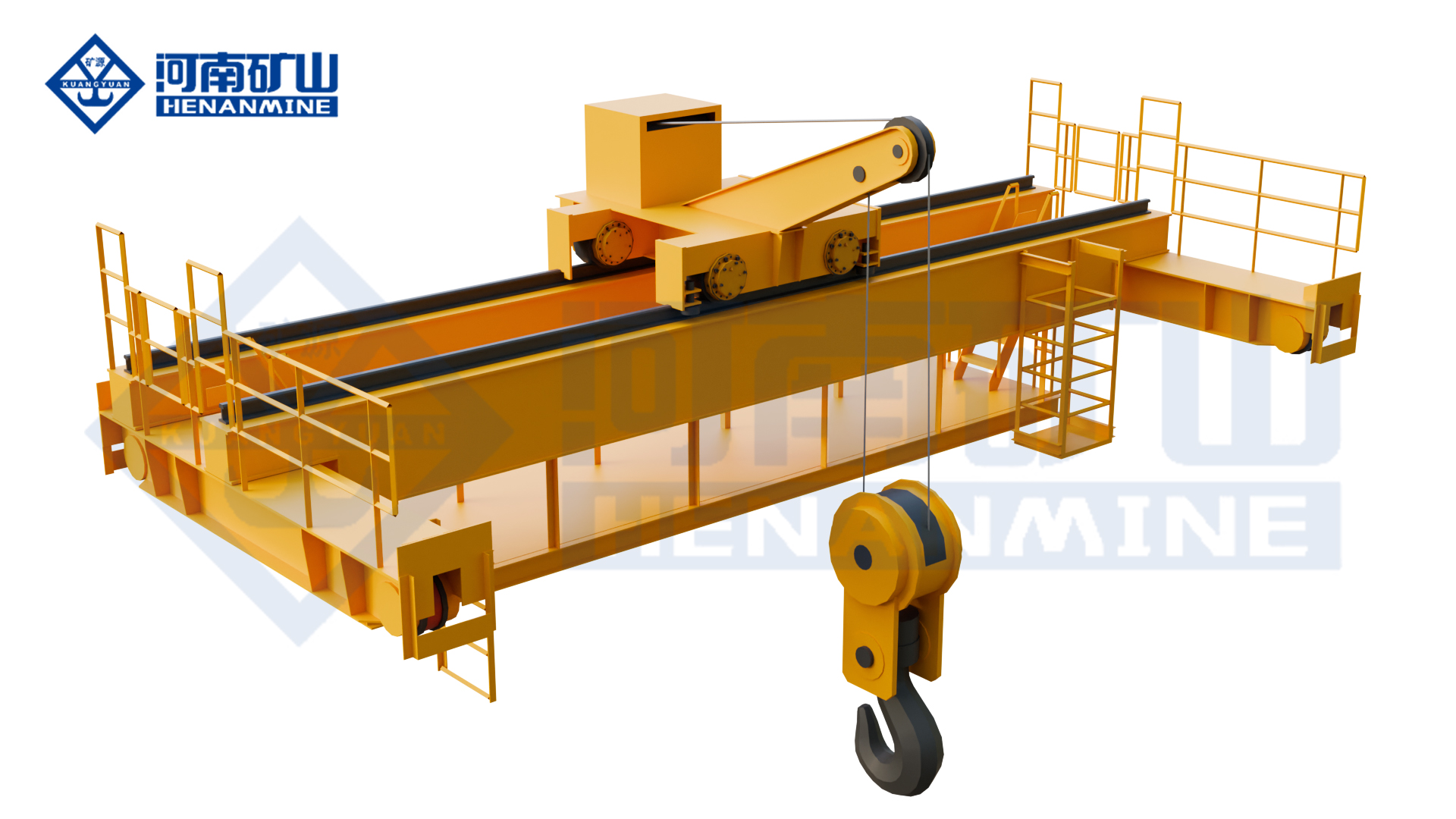
    Henan Mine CraneSelection guide · Updated 2026Crane selection, project scope and operating requirements
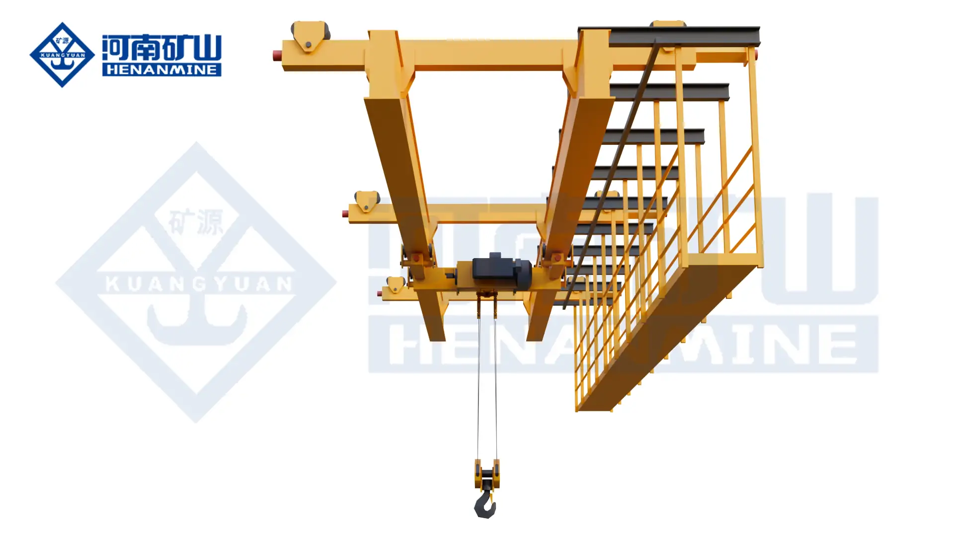
    Henan Mine Crane Galvanizing Process Overhead Crane
    Henan Mine Crane Galvanizing Process Overhead Crane
    Project planning notes

    Key points for this crane project.

    1. What Is a Copper Smelter Crane?
    2. Copper Smelter Crane Applications by Process Area
    3. Copper Smelter Crane System Architecture
    Read the technical guide

    What Is a Copper Smelter Crane?

    A copper smelter crane is a process-specific overhead lifting system used across primary copper smelting, secondary copper production or electrolytic refining. Depending on the process, it may move bulk concentrate and flux, charge boxes, matte or slag pots, molten blister copper, anode-furnace vessels, casting equipment, copper anodes and cathodes, furnace components or maintenance loads.

    The term describes an application family rather than one standard machine. A grab crane for dry concentrate uses a different hoist, attachment and environmental package from a casting crane carrying a full vessel of molten copper. A tankhouse process crane uses mechanical lifting frames and corrosion protection, while a maintenance crane may operate only during shutdowns at a much lower load spectrum.

    Henan Mine Crane develops these systems from its intelligent grab crane, metallurgical bin crane, double-girder casting crane, four-girder casting crane and general double-girder platforms according to the declared copper process.

    Copper Smelter Crane Applications by Process Area

    The crane schedule should follow the flowsheet and separate routine process lifts from maintenance lifts. The processing route varies between flash smelting, bath smelting, batch converting, continuous converting, secondary smelting and other technologies, so the actual plant process remains the design basis.

    Concentrate and Flux Handling

    Grab and transfer concentrate, silica flux, coke, recycled material or other approved bulk feed between storage, blending, bins and process interfaces.

    Furnace Charging and Bin Transfer

    Lift, position and empty charge boxes or bins through a controlled sequence coordinated with furnace doors, hoods, feeders and exclusion zones.

    Matte and Slag Pot Transfer

    Move declared molten or semi-molten vessels between furnace, converter, slag-cleaning and cooling positions using a purpose-designed load path and vessel attachment.

    Blister Copper and Anode Refining

    Support vessel transfer, furnace service and maintenance from converting through anode refining, with heat protection and interlocks matched to the operating route.

    Anode Casting and Product Handling

    Handle casting equipment, molds, ladles, anodes and maintenance assemblies around the casting wheel or mold line without conflicting with hot-metal routes.

    Electrorefinery Tankhouse

    Transfer anode and cathode groups, stripping-line loads or cell-service equipment with mechanical lifting frames, corrosion protection and busbar clearances.

    Acid Plant and Off-Gas Systems

    Provide maintenance lifting for fans, ducts, pumps, heat exchangers and process equipment with protection based on measured chemical exposure and area classification.

    Shutdown and Major Maintenance

    Remove furnace, converter, hood, electrode, burner, pump or drive components using planned maintenance clearances, drop zones and laydown areas.

    Copper Smelter Crane System Architecture

    1. Bridge and runway interface: transfer vertical, lateral, longitudinal, buffer and fatigue loads to the smelter building while maintaining furnace, hood and duct clearances.
    2. Process trolley and hoist: provide the main and auxiliary capacities, reeving, braking, drives, speed range and duty required for the declared vessel or material cycle.
    3. Load-handling device: connects to a charge box, pot, ladle, lifting trunnion, anode or cathode frame, grab, mechanical clamp, hook or maintenance spreader.
    4. Thermal and environmental package: protects structure, ropes, brakes, motors, panels, sensors and cab from radiant heat, dust, fumes, acid mist, condensation and corrosion.
    5. Safety and control system: coordinates limits, load monitoring, brakes, collision protection, restricted zones, process interlocks, safe states and controlled recovery.
    6. Power and plant interface: covers crane electrification, emergency-energy philosophy, PLC communication, operating modes, event records and interfaces with furnace, converter or casting equipment.

    Rated-load basis: capacity is based on the maximum gross suspended load. For a molten-material lift, include the vessel, refractory lining, maximum process contents, skull or adhered material where applicable, gantry beam or lifting frame, hooks, ropes and every suspended accessory. Main and auxiliary hook loads, tipping geometry and simultaneous operation require separate load cases.

    Copper Smelter Crane Selection Considerations

    Selection begins with the process function and credible operating cases. Nominal lifting capacity does not establish the required hoist redundancy, duty, attachment, heat protection, corrosion system or safe route.

    Process and Load Matrix

    Material or vessel identity, empty and full mass, temperature, dimensions, center of gravity, trunnions, attachment, normal cycle, abnormal condition and maintenance lifts.

    Production Duty

    Lifts per heat or batch, starts per hour, average and maximum load, travel distance, shifts, annual hours, standby time, production consequence of outage and maintenance window.

    Load Path and Interfaces

    Pickup, transfer and placement coordinates; furnace or converter status; casting equipment; vehicle crossings; occupied areas; emergency landing positions and interlocked machinery.

    Environmental Data

    Ambient and radiant temperature, duration of heat exposure, dust composition, SO₂ and acid mist, humidity, condensation, corrosive chemicals, washdown and hazardous-area classification.

    Building and Runway

    Rail-center span, runway length and elevation, headroom, hook approaches, wheel-load limits, clearances to ducts and hoods, expansion joints, rail condition and erection access.

    Safety and Acceptance

    Applicable law and standard, required redundancy, failure-response philosophy, operator location, access control, inspection route, representative-load tests and measurable process acceptance.

    Copper Smelter Crane Configurations Compared

    Each configuration addresses a different process load. Similar-looking bridge structures can contain materially different hoists, braking systems, attachments, controls and environmental protection.

    ConfigurationTypical Copper-Plant DutyLoad-Handling DeviceCritical Definition
    Intelligent Grab Overhead CraneConcentrate, flux, coke, return materials or approved dry bulk feed.Four-rope or application-specific grab.Material density, moisture, abrasiveness, grab fill factor, dust control and required tonnes per hour.
    Metallurgical Bin or Charge-Box CraneLifting, transferring and dumping charge boxes or process bins near a furnace.Forged hook, gantry attachment or custom box interface.Box geometry, tipping sequence, furnace-door and hood interlocks, heat exposure and spill boundary.
    Double-Girder Casting CraneMolten matte, slag, blister copper or anode copper vessel transfer within its engineered range.Gantry-type ladle beam or vessel attachment, with auxiliary hook where required.Gross vessel load, trunnions, main and auxiliary capacity, redundancy, heat protection and emergency landing.
    Four-Girder, Multi-Rail Casting CraneUltra-heavy or intensive molten-material duty requiring main and auxiliary trolleys.Main gantry attachment plus auxiliary forged hook.Trolley interaction, tipping load cases, wheel-load distribution, runway capacity and maintenance access.
    Tankhouse Process CraneAnode and cathode group transfer, cell service and stripping-line interfaces.Mechanical frame, hooks, clamps or custom group-lifting device.Plate spacing, electrolyte carryover, busbar clearance, electrical isolation strategy, corrosion and drip control.
    General Double-Girder Maintenance CraneFurnace, converter, hood, pump, fan and drive maintenance during planned access.Hook, sling or maintenance spreader.Heaviest maintenance assembly, infrequent-load spectrum, laydown area and shutdown access. Not a molten-metal crane unless specifically engineered and approved.

    Copper is not a ferromagnetic lifting load: ordinary electromagnetic lifting magnets used for steel do not provide the required holding method for copper anodes, cathodes, plate or scrap. Copper-product handling requires hooks, mechanical clamps, lifting frames, grabs or another engineered mechanical attachment.

    Published Metallurgical Crane Platform Ranges

    The following Henan Mine Crane product-page data provides an initial platform reference. These are not preselected copper-smelter specifications. Final capacity, span, lift, class, speeds, redundancy and attachment are determined by the approved process data.

    Copper Smelter Load Attachments

    The lifting device is part of the process system. Its geometry, rating, heat exposure, inspection method and failure consequences should be included in the crane design and acceptance plan.

    AttachmentTypical LoadEngineering Checks
    Four-Rope GrabConcentrate, flux and approved dry bulk material.Bulk density, moisture, particle size, cohesiveness, abrasion, grab fill factor and closing force.
    Charge-Box or Bin AttachmentFurnace feed boxes, bins and containers.Pickup points, latch confirmation, turnover angle, retained material, furnace clearance and release sequence.
    Gantry Ladle Beam or Vessel HookMatte, slag, blister-copper or anode-copper vessels.Trunnion profile, seating, side clearance, vessel tilt, refractory and contents mass, heat shielding and inspection access.
    Auxiliary Hook or Tipping DeviceControlled pouring, vessel rotation and maintenance assistance.Load sharing through the complete angle range, synchronization, rope fleet, prohibited positions and interlocks.
    Anode and Cathode Lifting FrameIndividual plates or defined groups in the tankhouse.Plate pitch, mass variation, engagement confirmation, busbar clearance, electrolyte drainage and short-circuit prevention.
    Maintenance Hook and SpreaderFurnace, converter, hood, pump, fan, motor and structural components.Approved lifting points, center of gravity, headroom, laydown position, sling angle and shutdown sequence.

    Molten-Material Safety and Failure Response

    A molten-copper crane is a process-safety system, not a general overhead crane with additional heat shields. The design basis must define what occurs after loss of one motor, reducer, brake, rope path, encoder, controller, incoming supply or communication link. The required redundant architecture depends on capacity, process risk, local law and the selected design standard.

    • Specify the main-hoist load path, service and emergency braking arrangement, upper-limit architecture and overspeed or unintended-motion protection where required.
    • Define whether a remaining drive can hold, lower or complete a controlled safe-placement cycle after a single failure.
    • Provide a predetermined landing or containment position for a retained molten load; emergency energy must have a stated function and duration.
    • Keep routine travel away from occupied rooms, control stations, escape routes and water hazards wherever the plant layout permits.
    • Interlock vessel transfer with furnace, converter, hood, door, aisle and casting equipment states as defined by the process hazard review.
    • Prohibit tandem or simultaneous operations unless the cranes, controls, load-sharing method and lift plan are engineered for that operation.

    Safety boundary: no personnel route should pass beneath a suspended vessel or load. The plant risk assessment defines access control, molten-material exclusion areas, spill response, emergency communications and restart authorization.

    Heat, Dust, Fume and Corrosion Protection

    Environmental protection should be zoned from measured exposure. Furnace-bay thermal radiation, concentrate dust, converter fumes, tankhouse acid mist and acid-plant chemicals do not produce the same failure mechanisms.

    Thermal Protection

    Heat shields, insulated structural zones, protected ropes and drums, high-temperature cables, suitable lubricants, remote panels and component-temperature monitoring are selected from exposure and duration.

    Dust Management

    Enclosures, filtration, positive-pressure cabinets, sealed bearings, accessible cleaning points and cable routing are matched to dust loading, conductivity and abrasion.

    Fume Exposure

    Cab location, filtered pressurization, HVAC intake position, remote operation, viewing systems and escape route are coordinated with SO₂ and other process-fume mapping.

    Corrosion System

    Surface preparation, coating, fasteners, enclosure materials, seals and corrosion allowance are chosen from chemical concentration, temperature, condensation and maintenance practice.

    Tankhouse Electrical Interface

    Busbar clearance, grounding, isolation, conductive-liquid carryover, prohibited bridging paths and fault-current consequences require coordination with the plant electrical design.

    Hazardous Areas

    Explosion-protected equipment is selected only from a documented zone, gas or dust group, temperature class and protection concept. A copper smelter is not automatically one uniform hazardous area.

    Controls, Interlocks and Process Integration

    Operating ModePrimary UseRequired Definition
    Cabin ControlIntensive furnace, converter or molten-vessel handling with a protected operator station.Sight lines, camera coverage, fume protection, HVAC, emergency exit, alarms and communication.
    Radio or Local ControlMaintenance and selected process moves where a safe operator position provides better visibility.Permitted zones, transmitter authorization, emergency stop coverage and mode-transfer interlocks.
    Assisted OperationOperator-initiated moves with protected routes, anti-sway, positioning or automatic approach.Control authority, target confirmation, obstacle response, restricted-zone logic and manual recovery.
    Automatic OperationRepeatable bulk-feed or defined production routes with controlled access and reliable process signals.Task handshake, permissives, safe states, sensor coverage, communication loss, exception handling and restart approval.

    A process signal matrix should identify command ownership and permissives for furnace doors, converter position, hoods, feeders, casting machines, aisle gates, other cranes and maintenance access. Event records should distinguish operator command, process refusal, safety trip, device fault and communication failure. Automatic operation does not remove the need for a verified local recovery procedure.

    Runway, Building and Maintainability Interfaces

    Wheel Loads and Fatigue

    Provide maximum, minimum and concurrent trolley wheel loads, lateral and longitudinal forces, buffers, fatigue spectrum and rail tolerances for structural verification.

    Process Clearances

    Coordinate bridge depth, trolley envelope, vessel swing, hook approach, hoods, ducts, stacks, columns, access platforms and operating equipment in every position.

    Runway Survey

    For an existing building, survey rail gauge, elevation, alignment, joints, wear, fasteners, beams, brackets, columns and foundations before final crane reactions are accepted.

    Maintenance Access

    Define platforms, guardrails, walkways, lighting, isolation points, component-removal routes, trolley service position and lifting points for crane maintenance.

    Critical Spares Strategy

    Identify brakes, ropes, wheels, bearings, encoders, drives, PLC modules, contactors, sensors, seals and attachment wear parts from production consequence and replacement lead time.

    Erection and Outage Plan

    Establish delivery splits, access opening, site lifting method, temporary works, outage duration, hot-work restrictions, tie-in sequence and commissioning area.

    Standards, Inspection and Acceptance Testing

    The contract should state the governing jurisdiction, standards and editions. A project basis may include ISO 4301 for classification, ISO 9927 for inspection, ISO 12480-1 for safe use, EN 13001 and EN 15011 for crane design, or CMAA 70 with ASME B30.2 requirements for the applicable overhead-crane arrangement. Electrical equipment may reference IEC 60204-32. Safety-related control systems may use ISO 13849-1 or IEC 62061 where applicable. Classified areas require the plant’s selected IEC 60079, ATEX, IECEx or local basis. Local law and the signed project specification remain controlling.

    Design Review

    Approve classifications, load cases, redundancy, structural and mechanism calculations, attachment drawings, wheel loads, environmental protection and safety functions.

    Manufacturing Records

    Define material traceability, welding procedure and personnel qualification, nondestructive examination, heat treatment, machining, assembly and coating records.

    Factory Acceptance

    Verify mechanisms, brakes, limits, overload system, control modes, alarms, process simulation, fault responses, interface signals and documentation before shipment.

    Site Acceptance

    Confirm runway geometry, commissioning tests, proof load, representative vessel or material handling, interlocks, protected routes, emergency functions and agreed production cycles.

    Published Heavy Metallurgical Crane Reference

    The delivered crane uses a four-girder, four-rail, dual-trolley arrangement for ultra-heavy molten-metal service and incorporates project-specific structural, hoisting, braking and thermal-protection measures.

    The reference demonstrates manufacturing and commissioning experience with a large-capacity metallurgical crane, including trolley coordination, high wheel loads, heat exposure and molten-material risk controls. Henan Mine Crane also publishes a four-girder casting-crane platform for steel and non-ferrous smelting applications, explicitly including molten copper handling in its application description.

    It demonstrates relevant engineering and manufacturing disciplines but does not define the capacity, redundancy, duty, attachment, performance, savings or acceptance criteria of another project.

    Copper Smelter Crane Price and Budget Scope

    A copper smelter crane price is established from process risk and total supply scope, not tonnage alone. Molten-material redundancy, main and auxiliary trolleys, vessel attachment, thermal protection, corrosion system, runway work, plant interfaces, testing and erection can change the investment substantially.

    The public market review below was completed on 20 September 2026. Public listings can change and frequently omit decisive engineering information. They are market observations rather than directly comparable installed-project quotations.

    Public ReferenceDisplayed ScopeCommercial Boundary
    Henan Mine Crane supplier listing: YZ metallurgical foundry double-girder casting craneConfigurable equipment listing; Qingdao port shownCapacity, span, vessel attachment, redundancy, freight, installation, runway and copper-process acceptance require a written proposal.
    Complete copper smelter crane packageOne or more process cranes, attachments, controls, runway interfaces and servicesRequires the process load schedule, duty, layout, environmental data, risk basis, standards, destination and defined delivery boundary.

    Reference sources: public supplier listings on Made-in-China. The displayed values do not constitute an offer from this page and should not be used as an installed-project budget without a technical and commercial scope review.

    Engineering and Procurement Deliverables

    A comparable bid separates crane performance, process interfaces and site services. The procurement package should identify deliverables and approval responsibilities before commercial comparison.

    Design Basis

    Process description, load cases, classifications, standards, redundancy philosophy, environment, reliability target, interfaces and exclusions.

    Calculation Package

    Structure, mechanisms, fatigue, ropes, drums, brakes, wheels, wheel loads, attachment, heat protection and safety-related controls as contractually required.

    Interface Drawings

    General arrangement, vessel and attachment, runway reactions, clearances, electrification, PLC signals, access, maintenance and erection splits.

    Inspection and Test Plan

    Hold points, traceability, welding records, nondestructive examination, factory tests, proof load, process simulation and site acceptance scenarios.

    Operating Documentation

    Manuals, inspection schedules, fault-response procedures, rescue and recovery, software backups, attachment register and operator training.

    Commercial Schedule

    Inclusions, exclusions, Incoterm, freight, civil work, erection, utilities, commissioning, spares, warranty, schedule and local support responsibility.

    Information Required for a Copper Smelter Crane Quote

    Complete enquiry data allows the crane, attachment, building interface, environmental protection and delivery scope to be selected and priced on one defined basis.

    Process and Load Data

    Smelting technology and process zone; material or vessel; empty, normal and maximum mass; temperature; dimensions; center of gravity; attachment and operating sequence.

    Vessel and Attachment Drawings

    Pot, ladle, bin, charge box, trunnion, tipping lug, anode/cathode frame, grab or spreader drawings with allowable contact and clearance zones.

    Duty and Production Cycle

    Cycles per heat or hour, shifts, annual hours, load spectrum, travel distances, simultaneous motions, speed targets, outage consequence and maintenance window.

    Plant Layout and Runway

    Plan and cross-section, span, runway length and elevation, rail data, wheel-load limits, process clearances, hot-load route, emergency position and installation access.

    Environment and Controls

    Ambient and radiant heat, dust, fumes, chemicals, humidity, corrosivity, hazardous-area classification, power supply, control mode, signals and plant communication protocol.

    Compliance and Commercial Scope

    Destination, standards, inspection route, Incoterm, freight, runway, installation, commissioning, load test, training, spares, documentation and warranty.

    Fastest route to a comparable proposal: submit the process flowsheet, lifting-equipment schedule, vessel and attachment drawings, workshop cross-section, load spectrum, environmental design data, runway information and required supply boundary. Unknown items can then be recorded as open points rather than hidden inside assumptions.

    Frequently Asked Questions

    Which crane is used in a copper smelter?

    Grab cranes handle dry bulk feed, bin cranes serve charge boxes, casting cranes handle approved molten-material vessels, tankhouse cranes move anodes and cathodes, and general double-girder cranes support maintenance. Each duty requires a separate specification.

    Can an electromagnetic crane lift copper?

    No conventional steel-lifting electromagnet should be specified for copper plate, anodes or cathodes because copper is not ferromagnetic. Mechanical hooks, frames, clamps, grabs or purpose-designed attachments are required.

    How is casting-crane capacity calculated?

    The basis is the heaviest gross suspended load: vessel, refractory, maximum process contents, adhered material, lifting beam, hooks and every accessory. Tipping, eccentric and simultaneous main/auxiliary-hook cases are evaluated separately.

    Is every copper smelter crane explosion-proof?

    Explosion protection is determined by the documented area classification, substance group, temperature class and selected protection concept. High temperature, corrosion resistance and explosion protection are different design requirements.

    What duty class is required?

    Molten-material and bulk-feed cranes commonly require high-duty classifications, while shutdown maintenance cranes may be lower duty. The correct class follows the load spectrum, cycles, speeds, annual hours and consequence of downtime.

    Can an existing runway be reused?

    Only after the rails, beams, brackets, columns, connections and foundations are surveyed and checked for condition, geometry, fatigue and the proposed vertical, lateral, longitudinal and dynamic reactions.

    How much does a copper smelter crane cost?

    A complete copper-smelter crane remains quotation-based because the published scopes are incomplete.

    What should be tested before handover?

    Testing should cover mechanisms, brakes, limits, overload protection, attachment engagement, representative loads, process interlocks, safe states, single-fault responses, emergency placement, proof load and agreed operating cycles.

    Related Copper Smelter Crane Products

    These Henan Mine Crane platforms cover principal bulk-feed, furnace charging, molten-material, heavy metallurgical, maintenance and integrated-control duties.

    YX Metallurgical Bin Crane

    High-duty platform for charge-box lifting, transfer and controlled dumping.

    Intelligent Grab Overhead Crane

    Four-rope grab platform for declared ore, concentrate, flux and slag duty.

    Double-Girder Bridge Crane

    General platform for process-area maintenance when molten loads are excluded.

    Automatic Metallurgical Crane

    Integrated control reference for defined production routes and plant signals.

    Submit the process area, maximum gross suspended load, vessel and attachment drawings, span, lift, operating cycle, environmental data, runway information, destination and required delivery scope. Henan Mine Crane will prepare a configuration and commercial proposal against the declared operating basis.

    Discuss the crane arrangement for your project.

    A smelter crane system needs defined handovers between lifting and production equipment. Map the transfer stages, control boundaries and environmental conditions so the suppliers can agree an integrated equipment scope. Share the load, available drawings, working cycle and site conditions with Henan Mine Crane so the required configuration and supply boundary can be discussed.

    Related crane configurations

    Galvanizing Process Overhead Crane

    View product parameters
    Lifting capacity: 5 – 32 tSpan: 10.5 – 31.5 mLifting height: 6 – 24 m

    Transfer suspended workpieces through a galvanizing process with a crane matched to the line. Coordinate lifting points, corrosive exposure, tank geometry and the required handling sequence.

    Updated 2026 · Henan Mine Crane
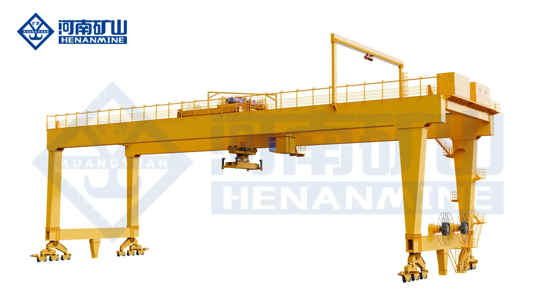
  • Container Yard Crane Selection: Compare Stacking and Transfer Duties

    Container Yard Crane Selection: Compare Stacking and Transfer Duties

    Selection guide

    Container Yard Crane Selection: Compare Stacking and Transfer Duties

    A yard crane must serve defined container positions and vehicle interfaces. Establish the handling cycle, stacking layout and supporting infrastructure before comparing the crane arrangements suitable for the terminal.

    Henan Mine CraneSelection guide · Updated 2026Crane selection, project scope and operating requirements
    Container Yard Crane
    Container Yard Crane
    Project planning notes

    Key points for this crane project.

    1. Application overview
    2. Container Handling Systems for Yard Stacking and Transfer
    3. Container Yard Crane Configurations
    Read the technical guide

    Application overview

    ApplicationsPorts, dry ports, rail terminals, logistics hubs and depots

    Primary systemsRMG, RTG, straddle carrier and fixed overhead crane

    Critical yard dataTEU demand, rows, tiers, lanes, rehandles and peak moves

    Commercial basisDefined interfaces, supply scope and project quotation

    Container Handling Systems for Yard Stacking and Transfer

    A container yard crane lifts, stacks and transfers ISO containers between storage blocks, terminal tractors, road trucks and railway wagons. The term covers several equipment concepts rather than one standard machine. Rail-mounted gantry cranes provide dense, repeatable coverage over fixed blocks; rubber-tyred gantry cranes combine block stacking with yard mobility; straddle carriers combine transport and stacking; and fixed container overhead cranes serve indoor or structurally supported bays.

    The required machine cannot be selected from rated tonnage alone. The engineering basis includes 20 ft, 40 ft and 45 ft container proportions, loaded and empty weights, reefer and hazardous-container rules, single- or twin-lift operation, row count, stacking tiers, truck or rail lanes, cantilever arrangement, peak moves per hour, annual TEU, required availability and planned automation.

    A ship-to-shore crane transfers containers between a vessel and the quay and is not normally the yard-stacking machine. The container yard crane receives the flow from quay tractors, rail wagons or road vehicles and controls storage density and retrieval performance. The interface between these systems is therefore included in terminal planning even when the equipment is purchased under separate contracts.

    Container Yard Crane Configurations

    01 · Rail-Mounted Gantry Crane

    An RMG travels on fixed rails and spans container rows plus truck or railway lanes. It supports high stacking density, precise positioning, electric power and advanced automation. Rail foundations, block alignment, storm restraints and a fixed operating envelope are integral to the project.

    02 · Rubber-Tyred Gantry Crane

    An RTG runs on rubber tyres and can serve different yard blocks when the pavement, steering system and traffic plan permit. Diesel-electric, hybrid, battery or externally electrified arrangements may be evaluated. Mobility must be balanced against tyre care, route control, energy supply and block-change time.

    03 · Container Straddle Carrier

    A straddle carrier lifts, carries and stacks containers with one mobile machine. It can reduce fixed rail infrastructure and provide flexible transfer between quay, yard and landside interfaces. Fleet sizing, traffic separation, turning space, pavement loading, battery charging or fuel service and maintenance access govern the operating concept.

    04 · Container Overhead Crane

    A container overhead crane runs on an elevated building or freestanding runway above a fixed bay. It is suitable for indoor transfer, manufacturing logistics, specialized depots or controlled rail and truck interfaces where weather protection and unobstructed floor access are required.

    05 · Automated RMG or RTG System

    Remote or automated operation can integrate anti-sway, absolute positioning, container recognition, truck-lane guidance, path control, collision avoidance and terminal operating system communication. Automation scope is defined with network architecture, data ownership, cybersecurity, recovery modes and manual intervention points.

    06 · Intermodal and Rail Yard Crane

    An intermodal yard crane spans railway tracks, truck lanes and storage rows to transfer containers between railcars and the stack. Rail operating windows, wagon profiles, track clearances, locomotive restrictions, grounding, signaling interfaces and terminal peak schedules become part of the design basis.

    RMG vs RTG vs Straddle Carrier

    The correct container yard crane follows the terminal operating model. Fixed high-density blocks generally favor RMG systems; flexible blocks and phased development can favor RTGs; integrated transfer and stacking can favor a straddle-carrier fleet. A lifecycle comparison should include civil works, energy, tyres or rails, staffing, automation, fleet redundancy and maintenance—not equipment price alone.

    SystemTypical operating fitPrimary strengthCritical infrastructure
    RMGHigh-density fixed blocks, rail terminals, dry ports and automated yardsPrecise rail guidance, electric operation and strong automation potentialRails, foundations, electrical distribution, drainage and storm anchoring
    RTGMarine and inland yards requiring block mobility or phased expansionCan relocate between compatible blocks without fixed travel railsPavement, marked routes, tyre service and diesel, hybrid, charging or conductor infrastructure
    Straddle carrierFlexible transfer-and-stack operations and shorter horizontal movesOne mobile unit carries and stacks without a separate terminal tractorTraffic lanes, turning space, pavement, fleet workshop and energy service
    Container overhead craneIndoor or fixed-bay container transfer and specialized industrial logisticsWeather-protected operation with clear floor-level accessBuilding runway or freestanding steelwork, foundations and power supply
    Ship-to-shore craneVessel-to-quay container transferQuayside ship service and outreach over vessel baysQuay rails, berth structure, power and waterside clearances

    Selection rule: specify RMG equipment where fixed block density, repeatable positioning, electric operation and automation justify rail infrastructure. Specify RTG equipment where block mobility and phased yard development have greater value. Specify straddle carriers where integrated horizontal transport and stacking provide the required flexibility. Hybrid layouts can combine systems when quay, rail and landside flows have different operating demands.

    Yard Capacity, Stacking Height and Throughput

    Annual TEU establishes the overall demand but does not define the crane quantity or speed by itself. Equipment sizing uses vessel, rail and truck peaks; dwell-time distribution; import, export and empty-container balance; reefer and hazardous segregation; rehandle strategy; maintenance windows; and the availability target for the complete yard system.

    Practical storage capacity is lower than the theoretical maximum because operational headroom is required for segregation, reshuffling, equipment access, maintenance and peak imbalance. A high nominal stacking tier can also increase rehandles and retrieval time. The preferred 1-over-X arrangement is therefore confirmed with the operating model rather than selected only to maximize static capacity.

    Cycle modeling includes spreader approach and engagement, hoisting, trolley travel, gantry travel where applicable, anti-sway settling, truck or wagon alignment, twistlock confirmation, set-down, release and operational delay. Representative long and short travel cases are tested. A single guaranteed moves-per-hour figure is only meaningful after the block geometry and operating assumptions are agreed.

    Crane quantity should preserve the required service when one unit is under planned maintenance or when adjacent blocks experience simultaneous peaks. Terminal simulation or a documented cycle model can compare alternative row counts, transfer lanes, cantilevers, stacking policies and fleet sizes before the final equipment schedule is frozen.

    Container Yard Application Matrix

    FacilityPreferred starting pointCritical operating dataEngineering focus
    Marine container terminalRTG, RMG or straddle-carrier system selected for the terminal conceptBerth peaks, tractor flow, vessel exchange, stack occupancy and gate demandQuay-to-yard balance, corrosion, wind, traffic segregation and availability
    Dry port or inland terminalRMG for fixed high-density blocks; RTG for flexible phased developmentTrain schedules, truck peaks, block length, expansion stages and power accessRail clearances, long travel, landside lanes, automation and future extension
    Rail intermodal yardLong-span RMG or mobile container handler fleetTrack count, wagon profile, train length, lift windows and locomotive movementRail signaling interfaces, electrification clearances and safe access control
    Empty-container depotRTG, straddle carrier or dedicated empty-container equipmentContainer tare range, stacking policy, inspection and repair flowHigh stacking utilization, lower payload, fast retrieval and damage control
    Reefer and hazardous zonesCompatible yard crane with controlled access and segregated blocksReefer rack layout, plug access, dangerous-goods classes and emergency plansClearances, fire strategy, access routes, electrical protection and operating rules
    Industrial container logisticsContainer overhead crane, RMG or compact RTGBuilding or yard envelope, truck lanes, production schedule and load statusFacility interfaces, headroom, foundations, controlled positioning and expansion

    Technical Specification Framework

    The specification is finalized from the container schedule, terminal layout, cycle model, environment and operating philosophy. Rated capacity under spreader, crane span, stacking height and working duty are important, but they do not define the complete container yard system.

    Henan Mine Crane converts the approved basis into a general arrangement, load and speed schedule, wheel or pavement reactions, spreader interface, power concept, control philosophy, safety-function schedule, data-interface list, inspection plan and itemized commercial boundary.

    Specification itemRequired project inputEngineering output
    Rated load under spreaderMaximum gross container mass, single or twin lift and special loadsSWL, spreader rating, overload strategy and structural design load
    Container interface20 ft, 40 ft and 45 ft mix, ISO corner fittings and load statusTelescopic spreader, twistlock monitoring, flippers and optional twin-lift arrangement
    Span and cantileversRow count, track or lane widths, clearances and transfer positionRail or tyre centers, trolley travel, end approaches and landside coverage
    Lifting height1-over-X stacking policy, vehicle or wagon height and required clearanceSpreader path, rope travel, upper clearance and maintenance access
    Working dutyMoves per hour, operating hours, load spectrum, availability and design lifeCrane and mechanism classifications with fatigue and thermal verification
    Motion performancePeak cycle requirement, travel distances and positioning toleranceHoist, trolley and gantry speeds, acceleration, anti-sway and precision modes
    Power systemGrid capacity, emissions policy, block mobility and energy objectivesCable reel, busbar, electric RTG, battery, hybrid or diesel-electric concept
    Control and automationCabin, remote or automated operation and TOS/RCMS interface requirementsPLC/VFD architecture, sensors, networks, data exchange and recovery modes

    Final values depend on the agreed container, yard, duty and code basis.

    Power, Automation, Safety and Environmental Protection

    Electric and Mobile Power

    RMG cranes commonly use cable reels or busbar systems. RTG and straddle-carrier projects can evaluate diesel-electric, hybrid, battery or externally electrified arrangements. Grid connection, charging demand, redundancy, cable routes, block mobility and lifecycle energy cost are reviewed together.

    Spreader and Load Confirmation

    Twistlock position, landed status, all-corners-locked confirmation, container size selection, load measurement and spreader cable management support controlled pickup. Interlocks prevent hoisting or travel when the defined engagement state is not achieved.

    Anti-Sway and Positioning

    Mechanical or electronic anti-sway, absolute position feedback, laser or camera guidance, truck alignment and controlled micro-speed can reduce settling time and support repeatable placement. Required positioning accuracy is defined for each interface.

    TOS, RCMS and Remote Operation

    Terminal operating system and crane management interfaces can exchange work orders, container identity, equipment status, alarms and completed moves. Remote-control stations require camera coverage, communications redundancy, ergonomic review and defined degraded-operation procedures.

    Collision and Traffic Protection

    Travel limits, buffers, anti-collision devices, obstacle detection, lane interlocks, warning systems, emergency stops and controlled access are coordinated with trucks, tractors, railcars, personnel and adjacent cranes. The functional design assigns responsibility for every interface.

    Wind and Outdoor Protection

    Anemometers, operating and parking wind limits, rail clamps, storm pins or anchors, lightning protection, corrosion-resistant coating, sealed enclosures, drainage and temperature-rated components are selected for the destination and agreed design conditions.

    5 t RMG for an International Inland Port

    The project demonstrates an RMG platform configured around fixed rail coverage and intermodal container handling.

    The published system incorporates Siemens PLC and variable-frequency drive control, anti-sway functions, a ring-trolley lifting mechanism and interchangeable upper and lower spreader frames. These functions support controlled positioning and operational flexibility across the defined container-handling tasks.

    A new inland-port project requires separate confirmation of rated load, rail and truck lanes, stacking tiers, span, travel length, lift height, duty, power distribution, terminal interfaces, wind conditions, civil loads and required automation. The project case establishes relevant design and delivery experience without replacing site-specific engineering.

    Engineering Deliverables and Quality Records

    A procurement-ready proposal defines the crane, spreader, power, automation, civil interfaces and acceptance boundary. Henan Mine Crane can prepare project-specific engineering and manufacturing records for technical approval, installation and commissioning.

    Approved container schedule, block layout, cycle model, load spectrum, duty calculation, wind data, availability target, code matrix and interface register.

    General arrangement, rail or pavement reactions, power demand, spreader data, TOS/RCMS signals, communications, civil tolerances and maintenance access.

    Material traceability, welding procedures, welder qualifications, dimensional inspection, NDT reports and component certificates as contractually required.

    Functional checks, brake and limit tests, spreader simulation, control sequences, alarm and interlock verification, data-interface tests and witnessed inspection when included.

    Review Henan Mine Crane manufacturing equipment and quality capabilities →

    Civil Works, Installation and Commissioning

    Before Manufacture

    Confirm the topographic survey, yard and lane geometry, rail alignment or pavement capacity, foundations, wheel loads, drainage, storm restraints, power route, substations, communications, maintenance facilities and division of site responsibilities.

    Erection and Integration

    Coordinate delivery sequence, unloading, site lifting, assembly, rail or tyre-path survey, electrical installation, spreader setup, TOS/RCMS data exchange, network testing, traffic control and access for terminal operations.

    Commissioning and Support

    Complete no-load and rated-load testing, container pickup trials, braking, anti-sway, travel, wind and emergency functions, interface tests, performance verification, operator and maintenance training, spare-parts handover and acceptance records.

    Commissioning should cover representative container sizes and weights, short and long travel cycles, truck or wagon positioning, twistlock states, degraded communications, power interruption, emergency recovery and the agreed wind operating limits. Performance acceptance uses the same operating assumptions defined in the contract.

    Container Yard Crane Price and Supply Scope

    Container yard crane price is determined by the selected equipment concept, rated load, span, stacking height, duty, motion performance, spreader, power system, automation, environment, civil interfaces, delivery term and installation responsibility. Published equipment prices should not be treated as turnkey terminal budgets.

    The following September 2026 ranges are preliminary market planning bands in US dollars. They are not a Henan Mine Crane quotation and are not directly comparable without matching technical scope, condition, design code, Incoterm, automation level, civil works and included services.

    Equipment or project levelCommercial interpretation
    Port-terminal or high-specification RTGHigher duty, electrification, automation, advanced positioning and terminal integration materially affect price
    High-specification or automated RMG projectAutomation, redundancy, long span, high duty, power distribution and software integration can dominate the project value
    Cost packageItems requiring an explicit quotation boundary
    Crane and spreaderSteel structure, mechanisms, cabin or remote station, telescopic spreader, anti-sway, controls, lighting and standard access
    Automation and data systemsOCR, position sensors, truck guidance, remote console, TOS/RCMS integration, servers, network, cybersecurity and software licenses
    Power and energy infrastructureSubstation, cable reel or busbar, e-RTG conductor system, battery and charger, hybrid or diesel package, fuel system and backup supply
    Civil and yard worksRails, foundations, pavement, drainage, storm anchors, reefer racks, barriers, road markings, buildings and maintenance facilities
    Logistics and installationPacking, inland haulage, ocean freight, insurance, unloading, erection, site cranes, supervision, permits and local labor
    Testing and lifecycle supportProof load, performance testing, third-party inspection, training, spare parts, maintenance tools, warranty, remote support and service response

    A valid bid comparison uses the same rated load under spreader, row and lane arrangement, stacking height, span, duty, speed schedule, spreader, power source, automation functions, environmental design basis, applicable code, Incoterm, currency, validity and site-responsibility matrix. Very low online listing prices frequently omit major project packages and should not be used as complete installed budgets.

    Container Yard Crane RFQ Information

    Submit the annual TEU and peak moves; container sizes, maximum gross mass and loaded/empty mix; reefer and hazardous-container requirements; yard drawing with block length, rows, lanes, stacking tiers and cantilevers; truck, rail and quay interfaces; average dwell time and rehandle assumptions; operating hours, duty and availability target; preferred RMG, RTG or straddle-carrier concept; power supply and emissions policy; control, automation, OCR and TOS/RCMS interfaces; temperature, wind, salt fog and seismic data; destination and applicable code; and the required freight, civil, installation, testing, training and spare-parts scope.

    Frequently Asked Questions

    What is a container yard crane?

    A container yard crane lifts, stacks and transfers ISO containers within a marine terminal, dry port, rail yard, logistics hub or depot. Common systems include RMG cranes, RTG cranes, straddle carriers and fixed container overhead cranes.

    Which is better for a container yard: RMG or RTG?

    RMG cranes are generally preferred for fixed, high-density blocks with electric power and substantial automation. RTG cranes are generally preferred where block mobility and phased expansion are more important. The final decision follows throughput, infrastructure, energy and lifecycle analysis.

    How is container yard crane capacity specified?

    Capacity is specified as rated load under the spreader for the defined single- or twin-lift operation. The spreader tare, container gross mass, dynamic loads, eccentricity, wind and structural load combinations are included in engineering verification.

    How many container rows and tiers can one crane cover?

    Coverage is project-specific. It depends on container width, clearances, truck or rail lanes, cantilevers, span, lifting height and stacking policy.

    Can a container yard crane handle 20 ft, 40 ft and 45 ft containers?

    A compatible telescopic spreader can be configured for the approved container lengths, corner fittings and load range. Container recognition, telescoping interlocks, twistlock status and flippers are defined within the spreader and control specification.

    Can an RMG or RTG be automated?

    Anti-sway, absolute positioning, container recognition, truck guidance, obstacle detection, remote operation and TOS/RCMS integration can support semi-automatic or automated service. Functional requirements, network architecture and recovery modes must be agreed before system design.

    What power options are available?

    RMG cranes commonly use grid power through cable reels or busbars. RTGs and straddle carriers may use diesel-electric, hybrid, battery or external electrification. Site grid capacity, block mobility, emissions objectives, charging schedule and redundancy determine the preferred system.

    How is yard crane throughput calculated?

    Throughput is modeled from spreader engagement, hoist, trolley and gantry travel, positioning, set-down, release and operating delays. Long and short cycles, rehandles, truck or rail arrival patterns, equipment availability and peak demand are included.

    What information is needed for a container yard crane quotation?

    Provide container sizes and weights, yard layout, rows, tiers, lanes, rated load, peak moves, annual TEU, duty, operating hours, power strategy, automation interfaces, environment, destination, applicable code, civil information and the required delivery and installation boundary.

    Prepared by Henan Mine Crane Technical Sales · Technically reviewed by Crane Engineering · Last reviewed September 2026

    Related Container Handling Products

    Rail-Mounted Container Gantry Crane

    Fixed-rail container stacking system for dense blocks, rail terminals, dry ports and automated yard operations.

    Rubber-Tyred Gantry Crane

    Mobile container stacking crane for flexible yard blocks with project-selected diesel, hybrid, battery or electric power.

    Container Straddle Carrier

    Mobile lift, carry and stacking equipment for flexible terminal transport and container-depot operations.

    Container Overhead Crane

    Elevated fixed-bay container crane for indoor transfer, manufacturing logistics and specialized rail or truck interfaces.

    Ship-to-Shore Container Crane

    Quayside container crane for vessel loading and unloading, coordinated with the terminal transfer and yard system.

    Automated Container Gantry Crane System

    A project reference for heavy-duty automated container handling with positioning, control and cold-climate engineering.

    Provide the container schedule, yard drawing, annual TEU, peak moves, rows, lanes, stacking tiers, truck or rail interfaces, duty, power strategy, automation scope, environment, destination and delivery boundary. Henan Mine Crane will develop the equipment, interfaces and commercial scope around the required terminal operation.

    Discuss the crane arrangement for your project.

    A yard crane must serve defined container positions and vehicle interfaces. Establish the handling cycle, stacking layout and supporting infrastructure before comparing the crane arrangements suitable for the terminal. Share the load, available drawings, working cycle and site conditions with Henan Mine Crane so the required configuration and supply boundary can be discussed.

    Related crane configurations

    Anode Carbon Block Stacking Crane

    View product parameters
    Lifting capacity: 10 – 30 tSpan: 13.5-40 mLifting height: 6 – 20 m

    Handle and stack anode carbon blocks with a crane configured around block geometry, gripping method and storage layout. Define the transfer sequence and automation interfaces before selection.

    Container Overhead Crane

    View product parameters
    Lifting capacity: 30-65 tSpan: 18-35 mLifting height: 8 – 20 m

    Transfer containers within a defined overhead runway area using a double-girder bridge and matched spreader. Container size, working clearance and the handling sequence determine the arrangement.

    Updated 2026 · Henan Mine Crane
  • Container Yard Crane Systems: Coordinate Blocks, Lanes and Equipment

    Container Yard Crane Systems: Coordinate Blocks, Lanes and Equipment

    Selection guide

    Container Yard Crane Systems: Coordinate Blocks, Lanes and Equipment

    A complete yard system needs the stacking equipment and transfer routes planned together. Define block geometry, traffic interfaces and operating responsibilities so individual crane choices support the wider container flow.

    Henan Mine CraneSelection guide · Updated 2026Crane selection, project scope and operating requirements
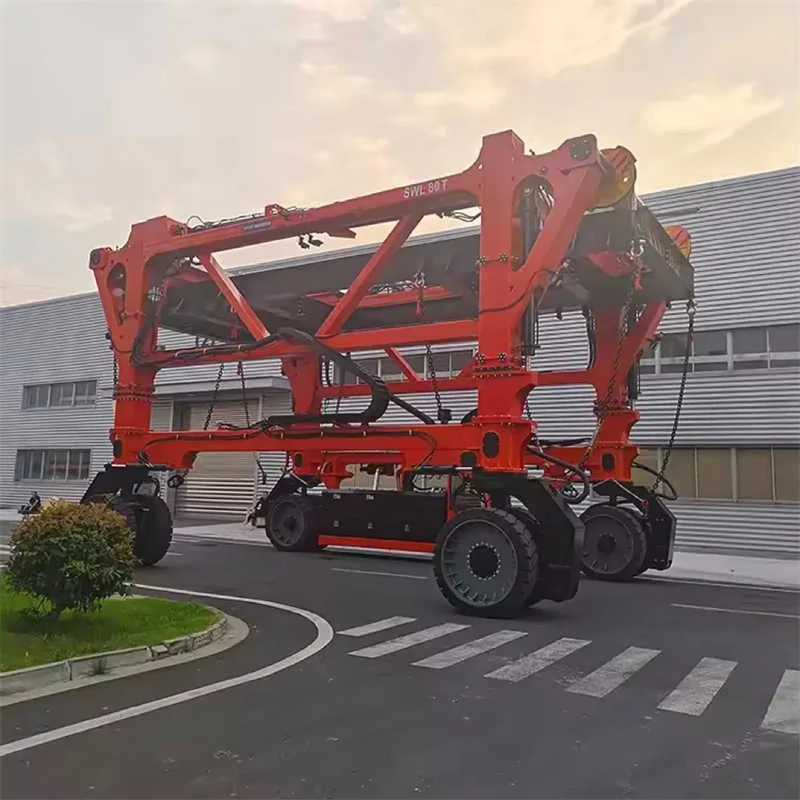
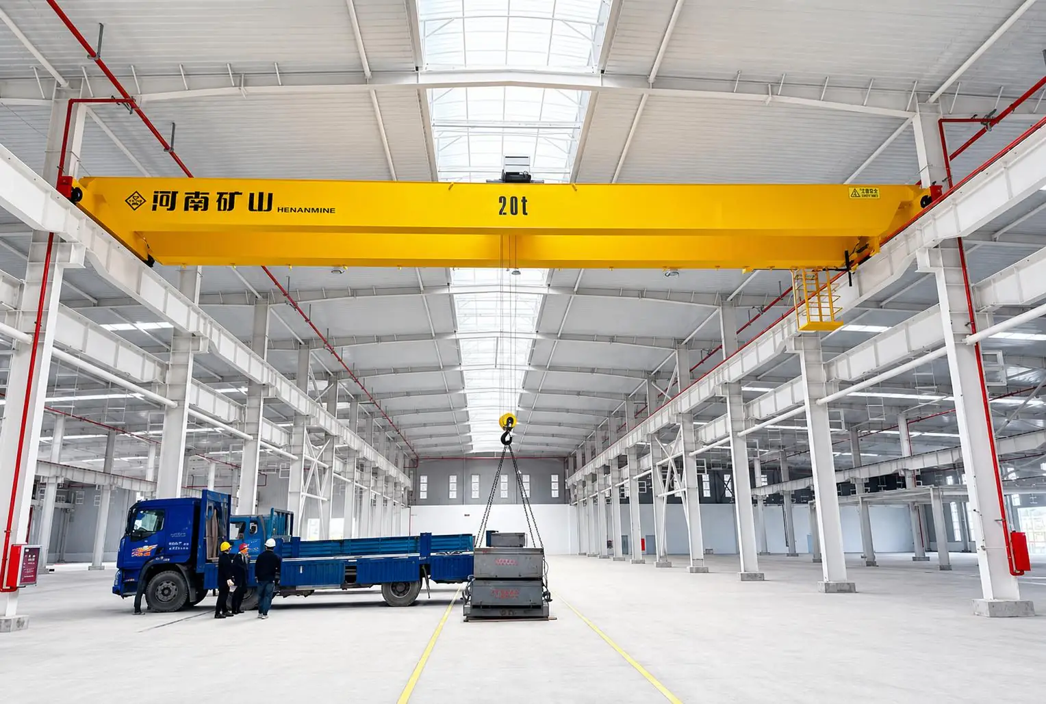
    container yard straddle carrier for transport and stacking
    container yard straddle carrier for transport and stacking
    Project planning notes

    Key points for this crane project.

    1. Application overview
    2. What Is a Container Yard Crane?
    3. Container Yard Crane Selection Considerations
    Read the technical guide

    Application overview

    20 ft, 40 ft and 45 ft Containers

    What Is a Container Yard Crane?

    A container yard crane lifts, stacks and transfers ISO containers inside a marine terminal, inland container depot, rail-intermodal facility, bonded logistics park or industrial distribution yard. Unlike an STS crane at the berth, a yard crane works between storage positions and landside or terminal-transport exchange lanes.

    The main configurations are rubber-tyred gantry cranes for mobile block service, rail-mounted gantry cranes for fixed high-density blocks, straddle carriers that combine transport and stacking, and fixed container overhead cranes for dedicated transfer bays. Each configuration changes the yard layout, civil works, fleet quantity, operating method and long-term cost.

    Henan Mine Crane supplies rubber-tyred gantry cranes, rail-mounted gantry cranes, container straddle carriers and container overhead cranes for new yards, capacity expansions and equipment replacement.

    Container Yard Crane Selection Considerations

    Annual and Peak Throughput

    Annual TEU, peak gate moves, vessel exchange peaks, rail windows, operating hours and reserve capacity establish crane quantity and duty.

    Block Geometry

    Rows under the span, truck lanes, stack height, block length, reefer aisles and maintenance access define span, lift and travel envelope.

    Container and Spreader Duty

    Container size, maximum gross mass, single or twin lift, empty-container share and out-of-gauge work determine rated load and spreader functions.

    Mobility and Layout Stability

    Changing blocks favor mobile RTG or straddle systems; permanent high-density blocks support rail-mounted and automated configurations.

    Civil and Power Infrastructure

    Pavement bearing, wheel loads, rails, settlement, drainage, substations, cable routes and charging or fueling strategy affect total project scope.

    Automation and TOS Interfaces

    Remote operation, positioning, OCR, truck guidance, equipment-control and terminal-operating-system interfaces require defined ownership and acceptance criteria.

    Container Yard Crane Configurations Compared

    ConfigurationOperating PatternMain StrengthPrimary Project Check
    Rubber-Tyred Gantry CraneServes one block and can relocate between blocksFlexible deployment without fixed travel railsPavement loads, steering, block-change route, power source and lane alignment
    Rail-Mounted Gantry CraneRuns on a permanent rail path over fixed blocks or rail tracksWide span, precise travel path and strong automation potentialRail civil works, settlement, cantilever, transfer zones and crane interference
    Container Straddle CarrierCombines horizontal transport, lifting and stackingFull-yard mobility with fewer equipment handoversTraffic management, lane width, pavement, fleet dispatch and visibility
    Container Overhead CraneFixed handling over a dedicated bay or covered transfer areaClear ground routes and controlled fixed-area operationRunway structure, building clearance, truck interface and spreader approach
    Automated Stacking Crane BlockDedicated RMG/ASC block with controlled transfer zonesRepeatable positioning, remote supervision and high storage densityTOS/ECS interfaces, safety zoning, recovery mode, data quality and acceptance testing

    Container Yard Layout Before Crane Selection

    Crane capacity alone does not establish yard performance. Block orientation, container dwell profile, import and export segregation, reefer positions, hazardous-container areas, empty stacks, truck appointments and rail schedules determine how often a crane must travel, rehandle or wait.

    The span is normally developed from the number of container rows, clearances and one or more truck or transfer lanes. Lift height follows the required stack height plus safe spreader clearance. Cantilevers add exchange positions without placing trucks inside the rail gauge, but they also increase structural and civil demands.

    Layout studies should model normal flow, peak-hour congestion, crane outages, maintenance access, emergency routes and future block expansion before final equipment quantities are released.

    Published Container Yard Crane Ranges

    The ranges below summarize published Henan Mine Crane product families. Final values are selected from the verified yard layout, rated load definition, duty spectrum, local code, wind data and interface requirements.

    RTG vs. RMG for a Container Yard

    RTG cranes suit phased terminals, changing block assignments and yards where fixed rail construction is not justified. Their block-change capability improves deployment flexibility, while steering control, tire condition, pavement quality and power transition require disciplined maintenance and operating procedures.

    RMG cranes suit stable blocks, high rail share, wide spans and automation-led operating concepts. Grid power and a fixed travel path support repeatable positioning, but rail foundations, settlement control and crane-interference management increase front-end engineering. A mixed fleet can retain RTG flexibility while dedicating RMG blocks to high-volume flows.

    A project comparison should include crane price, rails or pavement, electrical distribution, transfer equipment, labor model, energy, tire or rail maintenance, automation support, scheduled downtime and expected container moves over the evaluation period. The detailed RMG vs. RTG cost analysis provides an additional lifecycle framework.

    Fleet Sizing and Throughput

    The required fleet is based on peak moves rather than annual TEU alone. Productive moves per hour are reduced by trolley and gantry travel, spreader alignment, truck arrival variation, rehandles, block changes, shift transitions, maintenance and system delays. Reserve capacity is normally assigned for planned service and unplanned outages.

    Demand Profile

    Peak vessel exchanges, gate appointments, train windows and import dwell create the design workload.

    Cycle Components

    Hoist, trolley, gantry, alignment, twistlock confirmation and data handshakes define theoretical cycle time.

    Operational Allowance

    Traffic conflicts, rehandles, block changes, inspections and weather reduce net productive availability.

    Redundancy

    Maintenance reserve and recovery plans protect gate, rail and berth service commitments during crane outages.

    Spreader, Anti-Sway and Positioning

    FunctionSpecification ItemsAcceptance Evidence
    Telescopic Spreader20/40/45 ft, rated load, single or twin lift, flippers, skew and trimFunctional test, interlock test and proof-load documentation
    Anti-SwayPassive rope arrangement, active control, operating envelope and wind conditionMeasured residual sway under agreed cycles and loads
    Container PositioningStack profile, target coordinates, sensor coverage and reference systemRepeatability test across defined stack positions
    Truck GuidanceLane detection, chassis stop position, driver signal and exclusion zonesScenario testing for normal, offset and aborted approaches

    Power and Electrification Options

    Diesel-Electric RTG

    Independent block operation and relocation without fixed conductors; fuel, emissions, noise and engine maintenance remain lifecycle inputs.

    Hybrid or Battery RTG

    Stored energy and regeneration can reduce engine operating hours; battery duty, charging strategy and thermal management require cycle analysis.

    Cable-Reel or Busbar E-RTG

    Grid electricity supports lower local emissions; conductor layout, street crossing and off-grid block-change travel must be engineered.

    Grid-Powered RMG

    Fixed rails and electrical supply suit stable high-duty blocks; substation capacity, harmonics, cable management and backup strategy are included in system design.

    Automation and Terminal System Integration

    Automation scope can progress from operator-assistance functions to remote operation and fully automated stacking cycles. Typical functions include auto-steering, anti-sway, stack profiling, container positioning, truck guidance, collision prevention, equipment-condition monitoring and automated job reporting.

    The interface matrix identifies data ownership between the terminal operating system, equipment control system, crane PLC, OCR, positioning, gate and rail systems. Message timing, exception handling, cybersecurity, time synchronization and manual recovery are included in the functional design.

    Acceptance uses stated scenarios: normal container moves, wrong-container prevention, blocked lanes, lost communications, sensor degradation, emergency stops, power recovery and return to automatic service.

    Pavement, Rails and Civil Interfaces

    RTG wheel loads, tire pressure, turning zones and surface tolerance are coordinated with pavement design. Drainage grates, utility covers, crossfalls and transitions cannot interrupt steering or load distribution. Accurate lane markings and reference paths support auto-steering and truck positioning.

    RMG projects require verified rail gauge, rail elevation, straightness, foundation stiffness, differential settlement, end stops, buffers and storm anchoring. Wheel-load envelopes cover normal operation, acceleration, braking, wind and out-of-service conditions.

    Civil drawings and crane data sheets are exchanged before manufacture so wheel reactions, rail tolerances, conductor routes, cable pits and maintenance access are consistent across contracts.

    Safety, Wind and Marine Environment

    Load and Motion Protection

    Overload protection, hoist limits, overspeed protection, brakes, travel limits, buffers, emergency stops and fault monitoring are matched to the design code and risk assessment.

    Collision and Traffic Control

    Crane-to-crane protection, stack collision prevention, truck guidance, pedestrian exclusion and audible or visual warnings are defined by the operating concept.

    Wind Management

    Operating wind limits, alarm thresholds, parking procedures and out-of-service securing are established from site wind data and the selected structural code.

    Corrosion Protection

    Coating system, surface preparation, enclosed-component protection, stainless hardware and electrical enclosure ratings follow salt, humidity, rainfall and pollution exposure.

    Access and Maintenance

    Stairs, ladders, platforms, fall protection, machinery access, lighting, isolation points and component-removal routes support planned maintenance.

    Contract Codes

    Applicable ISO, FEM, EN, IEC, electrical, machinery and local port requirements are stated in the contract with an agreed document hierarchy.

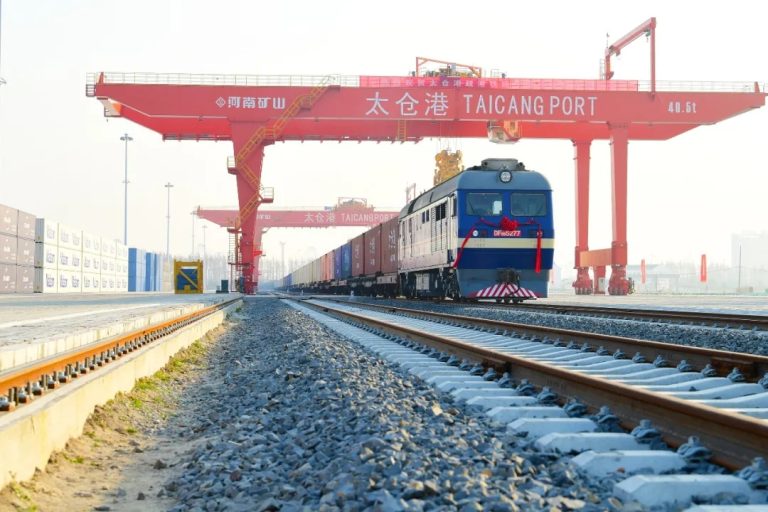
    Taicang Port International Hub

    The crane was configured as core container-yard handling equipment for an international logistics hub.

    The disclosed project functions include integration with the terminal logistics-management platform, remote operating-status visibility, automatic container seeking and lifting-device guidance. The lifting-device concept also supports interchangeability for containers and selected non-container cargo duties.

    This project demonstrates the combined engineering boundary of crane mechanics, spreader functions, positioning, controls and terminal data integration. Site-specific performance remains governed by the final contract and acceptance program.

    Container Yard Crane Price and Project Budget

    Public web prices reviewed in 2026 vary sharply because some values describe a basic equipment configuration, while public port contracts can include multiple cranes, controls, auxiliary equipment and system integration. Freight, duties, civil works, electrical infrastructure, erection, commissioning and terminal acceptance are separate unless expressly included.

    Public ReferenceCommercial Boundary
    Henan Mine Crane Yard SystemPrice follows geometry, duty, quantity, automation, civil interface, Incoterm and destination

    Engineering and Procurement Deliverables

    Technical Proposal

    General arrangement, design basis, load definition, duty, speeds, power, controls, spreader and environmental criteria.

    Civil Interface Data

    Wheel loads, rail gauge, tolerances, pavement reactions, conductor route, buffers, anchors and maintenance clearances.

    Electrical and Controls

    Single-line data, connected load, drive philosophy, control architecture, network requirements and interface register.

    Quality Documentation

    Inspection and test plan, material records, welding and NDT records, certificates, factory tests and document schedule.

    Site and Acceptance Scope

    Transport, erection, commissioning, proof load, functional trials, productivity tests, training and handover requirements.

    Lifecycle Support

    Recommended spares, special tools, preventive-maintenance schedule, remote diagnostics, warranty and service response.

    Container Yard Crane RFQ Data

    RFQ ItemInformation RequiredEngineering Use
    Operating DemandAnnual and peak TEU, gate moves, rail windows, dwell time, operating hours and target productivityConfiguration, quantity, duty and reserve
    Container Mix20/40/45 ft mix, maximum gross mass, reefer, empty, twin-lift and out-of-gauge dutyCapacity, spreader and load cases
    Yard LayoutBlock plan, rows, lanes, stack height, block length, rail or truck interfaces and expansion planSpan, lift, cantilever, travel and fleet arrangement
    Civil DataPavement capacity, rail gauge, foundation, settlement, drainage and storm-securing locationsWheel arrangement, reactions and securing system
    Power and ControlsVoltage, frequency, grid capacity, fuel or charging plan, operator mode and automation functionsPowertrain, electrical and control architecture
    Site EnvironmentOperating and storm wind, temperature, salt, humidity, rain, lightning, seismic and dust dataStructure, coatings, enclosures and operating limits
    Commercial ScopeDestination, Incoterm, code, civil works, installation, tests, training, spares and warrantyComparable technical and commercial quotation

    A preliminary concept can be prepared from the yard layout, throughput target, stacking pattern, container duty and site environment. A firm quotation requires verified civil interfaces, power data, automation boundaries, destination requirements and acceptance criteria.

    Container Yard Crane FAQ

    Is a container yard crane the same as a container gantry crane?

    Often, but not always. RTG and RMG cranes are container gantry cranes and are the most common yard systems. The broader term can also include straddle carriers and fixed container overhead cranes.

    Which crane suits a flexible or expanding yard?

    RTG cranes and straddle carriers can relocate without fixed travel rails. The final choice depends on stacking density, horizontal-transport concept, pavement, traffic and fleet size.

    Which crane suits a fixed high-density block?

    An RMG or automated stacking crane block can provide wide coverage, grid power and repeatable positioning when the yard layout and transfer zones remain stable.

    How are span and lifting height selected?

    Span covers the required container rows, clearances and truck or transfer lanes. Lifting height covers the specified stack plus safe spreader clearance and operating margin.

    Can a manual yard crane be prepared for later automation?

    Automation-ready design can reserve control capacity, sensors, networks, positioning references and safety interfaces. Later feasibility still depends on structure, drives, braking, data quality and the operating environment.

    What belongs in a turnkey yard-crane contract?

    The contract can include cranes, spreaders, electrification, controls, automation, selected rails or civil interfaces, freight, erection, commissioning, performance tests, training, spares and warranty. Included and excluded items should be scheduled explicitly.

    Related Container Yard Crane Products

    Rail-Mounted Gantry Crane

    Electric yard or rail crane for fixed blocks, wide spans and automation-led operations.

    Rubber-Tyred Gantry Crane

    Mobile yard crane for flexible block allocation and phased terminal expansion.

    Container Straddle Carrier

    Mobile equipment combining short-distance container transport, lifting and stacking.

    Container Overhead Crane

    Fixed-area container handling for inland depots, logistics bays and covered facilities.

    Ship-to-Shore Crane

    Quayside crane establishing the vessel-to-yard container flow at marine terminals.

    Portal Harbor Crane

    Flexible berth equipment for containers, general cargo and project cargo operations.

    Submit the yard layout, throughput target, container mix, stacking pattern, civil data, power supply, automation scope, site environment, destination and installation boundary for an engineered proposal.

    Discuss the crane arrangement for your project.

    A complete yard system needs the stacking equipment and transfer routes planned together. Define block geometry, traffic interfaces and operating responsibilities so individual crane choices support the wider container flow. Share the load, available drawings, working cycle and site conditions with Henan Mine Crane so the required configuration and supply boundary can be discussed.

    Related crane configurations

    Container Overhead Crane

    View product parameters
    Lifting capacity: 30-65 tSpan: 18-35 mLifting height: 8 – 20 m

    Transfer containers within a defined overhead runway area using a double-girder bridge and matched spreader. Container size, working clearance and the handling sequence determine the arrangement.

    Container Straddle Carrier

    View product parameters
    Lifting capacity: 30 – 50 tStacking arrangement: 1 over 3 – 1 over 6Working class: A7 – A8

    Move containers between handling positions with a straddle carrier matched to the travel route and stacking layout. Define container load, ground conditions, clearance and the preferred drive system.

    Updated 2026 · Henan Mine Crane
  • Container Terminal Cranes: Connect Waterside and Yard Operations

    Container Terminal Cranes: Connect Waterside and Yard Operations

    Selection guide

    Container Terminal Cranes: Connect Waterside and Yard Operations

    A terminal's crane requirements span several distinct cargo interfaces. Separate ship handling, stacking and intermodal transfer tasks before defining how the proposed equipment will work together within the operating system.

    Henan Mine CraneSelection guide · Updated 2026Crane selection, project scope and operating requirements
    automated container terminal crane serving a planned storage block
    automated container terminal crane serving a planned storage block
    Project planning notes

    Key points for this crane project.

    1. Application overview
    2. What Is a Container Terminal Crane?
    3. Container Flow from Vessel to Gate or Rail
    Read the technical guide

    Application overview

    20 ft, 40 ft and 45 ft Containers

    What Is a Container Terminal Crane?

    A container terminal crane is a purpose-built crane or coordinated crane system used to transfer ISO containers between vessels, terminal transport, storage blocks, road vehicles and rail wagons. The term can refer to a ship-to-shore crane at the quay, a rubber-tyred or rail-mounted yard crane, a straddle carrier, or a specialized intermodal crane.

    These machines do not perform the same job. An STS crane establishes the vessel interface. RTG and RMG cranes create yard density and serve trucks or transfer vehicles. Straddle carriers combine transport with stacking. Rail-terminal cranes span train tracks, storage lanes and truck lanes. Equipment selection therefore starts with the complete container flow rather than one isolated lifting capacity.

    Henan Mine Crane supplies ship-to-shore cranes, rubber-tyred gantry cranes, rail-mounted gantry cranes and container straddle carriers for new terminals, expansions and fleet replacement projects.

    Container Flow from Vessel to Gate or Rail

    A productive terminal matches the capacity of every transfer stage. Excess STS capacity cannot improve vessel turnaround when horizontal transport or yard blocks are congested. A dense RMG yard cannot reach design throughput when truck exchange positions, rail slots or gate appointments restrict the flow.

    The equipment schedule is developed from vessel calls, peak exchange volume, import and export dwell time, transshipment share, reefer demand, empty-container handling, rail share and planned operating hours.

    Vessel Interface

    STS cranes transfer containers between vessel cells and the quay apron according to ship geometry and stow plan.

    Horizontal Transport

    Terminal tractors, shuttle carriers, AGVs or straddle carriers connect the quay with assigned yard blocks.

    Yard Stacking

    RTG or RMG cranes stack containers by service, destination, dwell profile and retrieval sequence.

    Landside Exchange

    Truck lanes, rail tracks and inland-transfer positions complete the handover to road or rail transport.

    Container Terminal Crane Selection Considerations

    Vessel and Berth Profile

    Maximum vessel beam, container rows, hatch-cover arrangement, air draft, tidal range, rail gauge, wharf elevation and allowable quay loads establish the STS envelope.

    Throughput and Peak Demand

    Annual TEU, peak vessel exchange, operating windows, target berth productivity and acceptable queue time determine fleet size and redundancy.

    Yard Layout and Density

    Block length, lane count, stacking height, reefer rows, hazardous-container areas, empty stacks and truck or rail interfaces shape the yard-crane configuration.

    Container and Spreader Duty

    20 ft, 40 ft and 45 ft containers, single-lift, twin-lift, tandem duty, out-of-gauge loads and hatch covers define rated load and attachment functions.

    Power and Automation

    Grid capacity, cable route, busbar, battery or hybrid strategy, remote operation, OCR, positioning and terminal operating system interfaces are defined early.

    Marine Environment

    Operating and out-of-service wind, salt spray, humidity, rainfall, temperature, lightning, seismic criteria and storm securing affect structure and protection.

    Container Terminal Crane Configurations Compared

    ConfigurationTerminal PositionOperational StrengthMain Engineering Check
    Ship-to-Shore CraneQuayside berthDirect vessel loading and discharge with high hoist and trolley speedsOutreach, backreach, lift height, waterside clearance and wharf reactions
    Rubber-Tyred Gantry CraneFlexible yard blocksBlock-to-block mobility and phased yard expansion without fixed railsPavement loads, steering, travel routes, power source and block-change frequency
    Rail-Mounted Gantry CraneHigh-density yard or rail terminalStable rail path, wide spans and strong automation potentialRail civil works, block commitment, crane interference and transfer zones
    Container Straddle CarrierQuay-to-yard transport and stackingCombines horizontal transport, lifting and stacking in one mobile unitTraffic control, lane width, pavement, visibility and fleet dispatch
    Container Overhead CraneInland depot, covered transfer or fixed logistics bayDedicated fixed-area handling with clear ground routesBuilding runway, hook approach, spreader clearance and truck lane
    Portal Harbor CraneMultipurpose berthFlexible handling of containers, project cargo and general cargoWorking radius, lifting curve, berth rail, cargo mix and attachment changes

    Published Container Terminal Crane Ranges

    The following ranges are published by Henan Mine Crane for its terminal product platforms. They establish available equipment boundaries, not a preselected terminal specification. Final dimensions and ratings follow the agreed operational model and site data.

    Rated capacity is confirmed under the spreader or hook as stated in the project specification. Container weight, spreader deadweight, eccentric loading, wind and dynamic effects are included in the design load cases.

    Terminal Capacity and Fleet Sizing

    Crane quantity follows the peak operating scenario, not annual volume alone. The design model covers vessel arrival pattern, simultaneous berths, exchange size, gross crane rate target, planned maintenance, yard occupancy, rehandles, horizontal transport cycle, truck appointments and rail windows.

    Berth Crane Demand

    Required STS working positions, safe crane spacing, boom profile, hatch access, ship bay sequence and maintenance reserve establish the berth fleet.

    Yard Block Demand

    Stack height, lane count, dwell time, rehandle strategy, exchange positions and block occupancy establish RTG or RMG quantity.

    Transfer Fleet Demand

    Distance, route conflicts, charging or fueling, interchange time and dispatch logic determine tractor, AGV, shuttle or straddle-carrier fleet size.

    Maintenance Reserve

    Planned inspections, rope and spreader service, wheel or tyre work, storm securing and corrective maintenance are reflected in available fleet calculations.

    Future Expansion

    Reserved rail length, electrical capacity, data network, block extension, additional exchange lanes and larger vessel calls support staged investment.

    Performance Acceptance

    Contract targets state test conditions, container mix, route, operator mode, weather limit, availability basis and exclusions.

    RTG vs. RMG for Container Yard Operations

    RTG cranes suit terminals that value flexible block assignment, incremental expansion and the ability to relocate cranes. RMG cranes suit fixed, high-density blocks, rail terminals and automation programs where a stable travel path and grid power justify the rail infrastructure.

    The comparison includes pavement or rail civil works, electrical distribution, fleet dispatch, block-change losses, tyres or rail systems, energy use, maintenance access, automation scope and expected service life. Additional technical and lifecycle factors are covered in the RMG vs. RTG cost analysis.

    Decision FactorRTGRMG
    MobilityCan change blocks through approved terminal routesCommitted to a fixed rail path
    Civil WorksHeavy-duty pavement and wheel pathsRails, foundations, alignment and power route
    Power OptionsDiesel-electric, hybrid, battery or cable-fed electricNormally grid-electric through cable reel or conductor system
    Automation PathAvailable with steering, positioning and automated operationFixed geometry supports repeatable automated movement
    Planning PriorityFlexibility, phased growth and shared crane fleetDensity, electrification, rail service and long-term block stability

    Container Spreaders, Load Control and Motion Quality

    The spreader is part of the lifting system and acceptance scope. Container sizes, gross mass, eccentric loading, twin-lift duty, twistlock confirmation, telescoping time, flippers, skew and trim functions, cable management and diagnostic interface are specified with the crane.

    Single and Twin Lift

    Rated load and hoist arrangement reflect single 20/40/45 ft containers, twin 20 ft containers or a project-specific tandem configuration.

    Anti-Sway and Positioning

    Mechanical rope geometry, drive control, encoders and position references can reduce residual sway and support accurate ship, stack, truck or rail placement.

    Load and Twistlock Status

    Load measurement, landed confirmation, all-corners lock status and interlocks prevent lifting before the required engagement sequence is complete.

    Skew, Trim and List

    Controlled adjustment aligns containers with vessel cells, chassis, rail wagons and stacks where the working geometry requires compensation.

    Terminal Automation, Remote Operation and TOS Integration

    Automation can be introduced in stages: operator assistance, auto-steering, anti-sway, stack profiling, target positioning, remote operation, automated truck handling and fully automated yard cycles. Each stage requires an interface matrix between the crane controls, equipment control system, terminal operating system, OCR, vehicle management and safety systems.

    The functional specification states task messages, container identity, target coordinates, permission states, data ownership, network availability, clock synchronization, alarm handling, degraded modes and manual recovery. Cybersecurity architecture covers access control, network segmentation, remote service and software change management.

    Acceptance includes normal cycles, exception cases, lost communication, sensor disagreement, emergency stops, obstacle detection, controlled restart and traceable event records.

    Electrification and Lifecycle Cost

    Grid-Electric RMG and STS

    Substations, peak and regenerated power, harmonics, cable reels, conductor systems, emergency supply and energy metering are coordinated with the terminal grid.

    RTG Power Options

    Diesel-electric, hybrid, battery and cable-fed configurations are compared by block-change duty, grid availability, charging, fuel, maintenance and emissions targets.

    Total Cost of Ownership

    Civil works, equipment, energy, tyres or rails, ropes, brakes, spreaders, labor, software, planned downtime, spares and modernization are evaluated over the intended service life.

    Marine Environment, Wind Limits and Storm Securing

    Terminal cranes operate in wind, salt-laden air, rain, heat, cold and intensive ultraviolet exposure. The corrosion category, coating system, sealed and ventilated enclosures, stainless hardware, cable protection, drainage, dehumidification and inspection intervals are specified for the site.

    Operating wind, restricted-operation wind and out-of-service design wind are separate values. The storm plan identifies anemometer alarms, boom position, rail clamps, wheel brakes, storm pins, tie-downs, anchors, travel to securing points, backup power and authorized personnel.

    Wharf and yard drainage, lightning protection, seismic actions, settlement, rail alignment and pavement condition remain part of lifecycle inspection. Crane wind devices do not replace the terminal storm procedure.

    Safety, Standards and Acceptance Testing

    The purchase specification identifies the destination regulations and selected design framework. Common references can include ISO 4301-1 for classification, ISO 8686 for load actions, ISO 12488 for crane and rail tolerances, ISO 4302 for wind-load assessment, EN 13001 for crane design, IEC 60204-32 for electrical equipment and ISO container standards for dimensions and corner interfaces.

    Protective Functions

    Overload, overtravel, boom and trolley limits, anti-collision, gantry skew protection, emergency stop, storm alarms, restricted zones and safe isolation.

    Factory Acceptance Test

    Document review, drives, brakes, controls, spreader logic, alarms, interfaces, simulated faults, load testing and contracted performance functions.

    Site Acceptance Test

    Rails or pavement, power, rated and proof loads, spreader engagement, clearances, wind devices, interfaces, operating cycles and emergency recovery.

    Operational Acceptance

    Representative containers, vessel or yard positions, truck or rail exchange, TOS messages, automation exceptions and agreed productivity conditions.

    Taicang Port International Hub

    The crane serves container-yard handling and was configured for integration with the terminal’s logistics-management platform.

    Published functions include variable-frequency motion control, remote equipment monitoring, container-seeking assistance, lifting-device guidance and a changeable lifting-device concept for containers and other approved cargo forms.

    This case represents the yard-handling stage of a container terminal. STS berth equipment, horizontal transport, civil works and terminal interfaces remain separate project scopes unless expressly included in the contract.

    Container Terminal Crane Price and Project Budget

    Public prices reviewed in 2026 show why a container terminal crane cannot be budgeted from a generic gantry-crane listing. Equipment type, outreach, stacking geometry, automation, spreader, marine protection, civil works, electrical infrastructure, freight, erection and acceptance create materially different supply boundaries.

    Public ReferenceSupply LevelCommercial Boundary
    New RTG, Public Ex-Stock Listing, 2026Specific factory-built RTG configurationA listed unit price; freight, duties, site works, commissioning and terminal integration require confirmation
    Virginia Central Rail Yard, 2024Two rail bundles and three electric CRMGsCombined infrastructure and equipment reference, not a crane-only price
    Henan Mine Crane RTG, RMG or STSConfigured crane and agreed auxiliary packagePrice follows duty, geometry, spreader, controls, destination, Incoterm and service scope
    Automated Terminal Crane SystemCrane fleet, automation, interfaces and site systemsRequires an operating concept, interface matrix, civil and electrical boundaries, cybersecurity plan and acceptance schedule

    Engineering and Procurement Deliverables

    Design Basis

    Terminal flow, throughput, container mix, duty, environment, standards, operating modes, automation level and exclusions.

    General Arrangement

    Crane envelope, rails or wheel paths, outreach, lift heights, clearances, maintenance access, parking and storm positions.

    Civil and Electrical Loads

    Wheel loads, rail forces, storm loads, tie-down reactions, pavement loads, connected power, peaks, regeneration and earthing.

    Interface Control Document

    TOS, equipment control, OCR, network, power, civil works, spreader, transfer vehicles and safety-system responsibilities.

    Inspection and Test Plan

    Material records, manufacturing checks, load tests, spreader and control tests, interface simulation, site tests and hold points.

    Commercial Schedule

    Price, Incoterm, milestones, freight, erection, commissioning, acceptance, documentation, training, spares, warranty and exclusions.

    Container Terminal Crane RFQ Data

    RFQ ItemInformation RequiredEngineering Use
    Terminal OperationAnnual and peak TEU, vessel calls, rail share, dwell time, operating hours and target productivityEquipment type, fleet quantity, duty and reserve
    Containers and Loads20/40/45 ft mix, maximum gross mass, twin lift, out-of-gauge and hatch-cover dutyCapacity, spreader and load cases
    Berth or Yard GeometryVessel profile, wharf section, rails, blocks, lanes, stack height, truck and rail interfacesOutreach, span, lift, clearance and travel envelope
    Civil InterfaceAllowable wheel or pavement loads, rail gauge, foundation data, settlement and storm anchorsCrane structure, wheel arrangement and securing system
    Power and ControlsVoltage, frequency, grid capacity, power-delivery method, operator mode and automation functionsDrive, electrical, energy and control architecture
    Site EnvironmentWind, temperature, humidity, salt spray, rain, lightning, seismic and corrosion requirementsDesign loads, coatings, enclosures and storm system
    Commercial BoundaryDestination, code, Incoterm, installation, commissioning, testing, training, spares and warrantyComparable technical and commercial quotation

    A preliminary concept can be prepared from the terminal layout, throughput target, vessel or yard geometry and maximum container duty. A firm quotation requires verified civil interfaces, environmental data, automation boundaries, destination requirements and acceptance criteria.

    Container Terminal Crane FAQ

    Is a container terminal crane the same as an STS crane?

    STS refers specifically to the quayside vessel crane. Container terminal crane is a broader term that can include STS, RTG, RMG, straddle carriers and intermodal container cranes.

    Which yard crane provides the highest flexibility?

    RTG cranes can relocate between blocks and support phased layouts. RMG cranes remain on fixed rails but can provide wider spans, stable grid power and a strong automation platform.

    How is STS outreach selected?

    Outreach follows the maximum vessel beam, container rows, waterside rail position, fender line, lashing platform and required service margin. Future vessel classes should be included where berth expansion is planned.

    Can existing terminal cranes be automated later?

    Some cranes can receive positioning, anti-sway, remote-operation or automated functions after structural, electrical, control, sensor, network and safety assessments. Interface capacity and remaining design life affect feasibility.

    What is included in a turnkey terminal crane quotation?

    The contract can include crane equipment, spreader, electrification, automation, rails or selected civil interfaces, freight, erection, commissioning, testing, training and spares. Every included and excluded item should appear in the commercial schedule.

    What determines delivery time?

    Concept approval, detailed engineering, long-lead drives and spreaders, structural fabrication, controls, factory testing, ocean transport, civil readiness, erection method and site integration determine the project schedule.

    Related Container Terminal Crane Products

    Ship-to-Shore Crane

    Quayside crane for container transfer between vessels and the terminal apron.

    Rail-Mounted Gantry Crane

    Electric yard or rail crane for high-density stacking and automated operations.

    Rubber-Tyred Gantry Crane

    Mobile yard crane for flexible block allocation and phased terminal development.

    Container Straddle Carrier

    Mobile equipment combining container transport, lifting and stacking functions.

    Portal Harbor Crane

    Flexible berth crane for containers, general cargo and project cargo operations.

    Container Overhead Crane

    Fixed-area container handling for inland depots, logistics bays and covered facilities.

    Submit the terminal layout, throughput target, vessel or yard geometry, container duty, site environment, power data, automation scope, destination and installation boundary for an engineered proposal.

    Discuss the crane arrangement for your project.

    A terminal's crane requirements span several distinct cargo interfaces. Separate ship handling, stacking and intermodal transfer tasks before defining how the proposed equipment will work together within the operating system. Share the load, available drawings, working cycle and site conditions with Henan Mine Crane so the required configuration and supply boundary can be discussed.

    Related crane configurations

    Container Overhead Crane

    View product parameters
    Lifting capacity: 30-65 tSpan: 18-35 mLifting height: 8 – 20 m

    Transfer containers within a defined overhead runway area using a double-girder bridge and matched spreader. Container size, working clearance and the handling sequence determine the arrangement.

    Container Straddle Carrier

    View product parameters
    Lifting capacity: 30 – 50 tStacking arrangement: 1 over 3 – 1 over 6Working class: A7 – A8

    Move containers between handling positions with a straddle carrier matched to the travel route and stacking layout. Define container load, ground conditions, clearance and the preferred drive system.

    Updated 2026 · Henan Mine Crane

  • Container Gantry Crane Enquiries: Spreader, Stacking and Support Inputs

    Container Gantry Crane Enquiries: Spreader, Stacking and Support Inputs

    Selection guide

    Container Gantry Crane Enquiries: Spreader, Stacking and Support Inputs

    A container gantry proposal needs the load basis and working area defined consistently. Provide container modes, stacking positions, transfer lanes and runway or ground information before comparing configurations.

    Henan Mine CraneSelection guide · Updated 2026Crane selection, project scope and operating requirements
    Container Gantry Crane
    Container Gantry Crane
    Project planning notes

    Key points for this crane project.

    1. Container Yard Handling Systems
    2. Container Gantry Crane Selection Considerations
    3. RMG vs RTG Container Gantry Cranes
    Read the technical guide

    Container Yard Handling Systems

    A container gantry crane travels over a defined yard operating area and uses a container spreader to lift, transfer and stack containers between storage positions and truck or rail interfaces. A rail-mounted crane follows fixed tracks; a rubber-tyred crane travels on the prepared yard pavement. Both are yard-handling systems, not substitutes for a ship-to-shore crane serving the vessel at the quay.

    The correct specification follows the terminal’s operating plan: container mix, maximum gross load, stack density, target moves, truck or wagon access, available electrical capacity and site conditions. Capacity must be stated clearly as the permitted load under the spreader, with spreader weight and other lifted attachments accounted for in the crane design.

    Container Gantry Crane Selection Considerations

    The following inputs determine equipment geometry, cycle capability and the limits of the supply package.

    01 · Yard Layout

    Confirm block length, container rows, truck or rail lane location, end clearances and permissible crane travel limits.

    02 · Load Basis

    State maximum container gross mass, rated load under spreader and the spreader type and mass.

    03 · Stack Height

    Specify target tiers, clearance over the top container, spreader headroom and the highest required lift point.

    04 · Operating Demand

    Provide projected peak moves, annual volume, operating shifts and the required availability and redundancy plan.

    05 · Power Supply

    Assess fixed power feed, cable or conductor arrangements, generator use and the feasibility of RTG electrification.

    06 · Ground Interface

    Check rail alignment and foundations for RMG or pavement bearing, tyre paths and turning space for RTG.

    07 · Site Exposure

    Establish working and parked wind conditions, seismic criteria where applicable, temperature and salt exposure.

    08 · Control Interface

    Define operator station, positioning aids, telemetry, yard-system interfaces and the intended level of automation.

    RMG vs RTG Container Gantry Cranes

    Both configurations handle containers in the yard. The distinction is how the crane moves and how the terminal must support that movement.

    Selection factorRMG · Rail-mountedRTG · Rubber-tyred
    RouteFixed rail-served blockTravels on prepared pavement; movement between blocks depends on yard design
    Civil interfaceRails, foundations and rail alignmentPavement bearing, tyre travel paths and turning space
    Power conceptUsually fixed electrical feedGenerator or electrified arrangement, subject to block layout
    Best fitStable, high-density blocks and rail intermodal terminalsYards prioritizing operational flexibility and block reassignment
    Principal trade-offLess route flexibility; rail infrastructure requiredPavement and tyre loading plus mobile power strategy

    An RMG proposal should include the required rail and power interface data. An RTG proposal should establish pavement loading, turning conditions and the selected power architecture. Neither crane type replaces quay-side ship-to-shore handling.

    Engineering Specifications to Confirm

    ParameterProject definition
    Span and outreachDerive from row count, container spacing, truck lane, crane clearance and any cantilever requirement.
    Lifting heightDerive from planned stacking tiers, container height, spreader dimensions and safe travel clearance.
    Container handlingSpecify 20 ft, 40 ft and any 45 ft units; confirm telescopic spreader, twistlock indication and any twin-lift requirement separately.
    Duty and motionSelect hoisting, trolley and gantry speeds from duty profile and yard movement study; do not substitute a theoretical cycle for guaranteed throughput.
    Electrical and controlConfirm voltage, frequency, energy supply, cabin or remote operation and required terminal-system interfaces.

    Final dimensions, speeds, classification and utility demand are stated in the approved technical specification and drawings.

    Spreader, Drives and Yard Controls

    The spreader specification must match the container fleet and handling method. Telescoping range, twistlock feedback, flipper arrangement, permissible eccentric load and container identification functions should be settled before the crane is ordered. Single-lift and twin-lift operations require different structural, spreader and handling assessments.

    Variable-speed drives, controlled acceleration, anti-sway functions and precise trolley positioning can be configured to support repeatable yard handling. Electrical choices also influence maintenance, spare-parts inventory and site power infrastructure. Yard-management integration, remote control and automation are separately defined interfaces—not default inclusions.

    Operational safety provisions are evaluated against the actual design and applicable site rules, including overload protection, emergency stops, travel-limit protection, warning devices, storm parking arrangements and safe access for maintenance. The approved specification identifies which features are supplied and how they are tested.

    Container Yard Application: 40.5 t RMG Configuration

    Its planning emphasis is rail-served container handling, stack access and integration of the crane with the inland terminal’s traffic flow.

    This published application illustrates a proposed configuration; it does not establish a specific delivered terminal, accepted performance figure or operating record. Project-specific evidence, drawings, inspection records and reference availability can be addressed during technical qualification.

    Manufacturing, Inspection and Project Handover

    Henan Mine Crane designs the crane structure and operating systems to the agreed load case, environmental criteria and project specification. Procurement documentation can define general arrangement drawings, principal component schedule, electrical requirements, inspection and test plan, coating specification, manuals and spare-parts list.

    The contract should identify the applicable standards and inspection responsibilities before manufacture. Factory inspection, pre-shipment checks, site assembly, commissioning tests, operator training and acceptance records are specified according to the agreed supply and service scope. Regulatory approvals and independent inspection requirements vary by destination and should be identified in the inquiry.

    Installation planning must cover access for oversized components, lifting equipment for erection, rail or pavement readiness, site power, commissioning resources and handover responsibilities. These items materially affect schedule and landed cost.

    Container Gantry Crane Price and Project Cost

    Container gantry cranes are engineered capital equipment, and a public unit price cannot represent a complete terminal project. RMG and RTG quotations are not directly comparable until rated load, span, lift height, duty, spreader, controls, power supply and site service scope are aligned. Automation and electrification can substantially change both the initial investment and the operating-cost model.

    Equipment Supply

    Crane structure, drives, electrical cabinets, spreader, controls, safety provisions, factory inspection and specified spares.

    Terminal Infrastructure

    Rails and foundations or yard pavement, electrical distribution, cable systems, communications and operating-area preparation.

    Delivery and Commissioning

    Packing, inland and ocean freight, duties where applicable, site assembly, tests, training and post-handover support.

    A comparable quotation states the Incoterm, included equipment, exclusions, currency, payment basis, warranty terms and site-service responsibilities. Submit the terminal layout and technical duty schedule for a project-specific commercial offer.

    Information Required for a Technical Proposal

    A complete inquiry includes the terminal or rail-yard plan; container sizes and maximum gross mass; required load under spreader; target rows, tiers and handling lane; planned peak moves and shifts; RMG or RTG preference; available voltage and power concept; site wind and environmental data; civil status; desired controls and yard-system interface; destination port; and the requested delivery, installation and commissioning scope.

    Where the terminal layout is still being developed, concept drawings and throughput targets permit a preliminary configuration. The final equipment design and commercial offer follow confirmation of the operating envelope and interface responsibilities.

    Frequently Asked Questions

    What is a container gantry crane used for?

    It lifts and stacks containers in terminal, depot and intermodal yard operating blocks.

    What is the difference between RMG and RTG?

    An RMG follows a fixed rail route; an RTG runs on tyres over a prepared yard surface.

    Is an RMG suitable for rail intermodal terminals?

    Yes, where the crane’s rail-served envelope, wagon access and yard traffic plan are coordinated.

    Can an RTG move between yard blocks?

    Block-to-block movement depends on the crane’s steering configuration, pavement, turning geometry and power connections.

    How is container crane lifting capacity defined?

    Specify the permitted container load under the spreader and account separately for spreader and attachment masses.

    Can the crane handle 20 ft and 40 ft containers?

    A suitably specified telescopic spreader can handle both; 45 ft, twin-lift and special containers require confirmation.

    How many container tiers can it stack?

    The number depends on lifting height, container height, spreader headroom and travel clearance.

    Is an electric RTG available?

    Electrified RTG concepts can be evaluated where yard layout and electrical infrastructure support the selected supply arrangement.

    Does the price include rails and installation?

    Only when expressly included. Civil works, freight, site assembly and commissioning must be identified in the quotation.

    What determines the delivery schedule?

    Engineering approval, component selection, manufacturing scope, inspection, shipment and site readiness establish the project schedule.

    Related Container and Port Equipment

    Rail-Mounted Gantry Crane (RMG)

    Fixed-track stacking for container yards and intermodal facilities.

    Rubber-Tyred Gantry Crane (RTG)

    Mobile tyre-mounted container stacking across designed yard blocks.

    Container Straddle Carrier

    Alternative equipment for container transfer and yard stacking.

    Ship-to-Shore Crane (STS)

    Quayside vessel handling upstream of container yard operations.

    Port Crane Product Range

    Explore the full terminal and cargo-handling equipment portfolio.

    Provide the yard layout, maximum container mass, stack rows and tiers, target handling volume, preferred RMG or RTG arrangement, power information and installation destination. Henan Mine Crane will develop a technical configuration and clearly scoped commercial proposal.

    Discuss the crane arrangement for your project.

    A container gantry proposal needs the load basis and working area defined consistently. Provide container modes, stacking positions, transfer lanes and runway or ground information before comparing configurations. Share the load, available drawings, working cycle and site conditions with Henan Mine Crane so the required configuration and supply boundary can be discussed.

    Related crane configurations

    Anode Carbon Block Stacking Crane

    View product parameters
    Lifting capacity: 10 – 30 tSpan: 13.5-40 mLifting height: 6 – 20 m

    Handle and stack anode carbon blocks with a crane configured around block geometry, gripping method and storage layout. Define the transfer sequence and automation interfaces before selection.

    Container Overhead Crane

    View product parameters
    Lifting capacity: 30-65 tSpan: 18-35 mLifting height: 8 – 20 m

    Transfer containers within a defined overhead runway area using a double-girder bridge and matched spreader. Container size, working clearance and the handling sequence determine the arrangement.

    Updated 2026 · Henan Mine Crane

  • Automotive Coil Handling Cranes: Storage, Uncoiling and Transfer Requirements

    Automotive Coil Handling Cranes: Storage, Uncoiling and Transfer Requirements

    Selection guide

    Automotive Coil Handling Cranes: Storage, Uncoiling and Transfer Requirements

    Automotive coil operations need the lifting arrangement coordinated with the storage and production route. Define coil geometry, presentation and handling points so attachments and crane coverage can be reviewed for the actual process.

    Henan Mine CraneSelection guide · Updated 2026Crane selection, project scope and operating requirements
    Henan Mine Crane Upper Rotating Magnetic Overhead Crane
    Henan Mine Crane Upper Rotating Magnetic Overhead Crane
    Project planning notes

    Key points for this crane project.

    1. What Coil Handling in an Automotive Plant Involves
    2. Where Coil Cranes Work in an Automotive Plant
    3. Attachments and Configurations for Coil Service
    Read the technical guide

    What Coil Handling in an Automotive Plant Involves

    A coil handling crane for the automotive industry moves steel and aluminium coils between storage, preparation and the press lines that turn them into body panels. The crane is the link between every one of those positions, and its cycle is tied directly to line demand rather than to a schedule of its own.

    What separates automotive coil handling from general coil service is the surface. A large share of automotive sheet carries exposed or pre-coated finishes destined for visible body panels, where any mark on the coil surface becomes a defect in a stamped part. The crane, the C-hook or tong that carries the coil, the saddle it rests on and the way it is set down all have to preserve the surface class of the material — with protective linings, controlled contact pressure and smooth acceleration and deceleration engineered in from the start.

    The attachment defines the machine. C-hooks and mechanical tongs handle any material including non-ferrous and coated coil; magnetic beams pick ferrous coils at speed but depend on material, temperature and surface condition. Rotating beams and slewing trolleys turn coils between eye orientations.

    Henan Mine Crane supplies automotive coil handling systems as engineered packages: the crane structure and machinery, the C-hook, tong or magnetic attachment with its power and control, storage saddle and rack interfaces, safety functions and documentation — configured against the coil schedule and cycle rate of the specific plant.

    Where Coil Cranes Work in an Automotive Plant

    Coil Storage and Rack Handling

    Cranes place and retrieve coils from storage racks, saddles and stacked positions. Placement accuracy protects both the coil surface and the rack structure, and the storage layout defines the coverage the crane has to deliver.

    Blanking Line Feed

    Coils are delivered to blanking and cut-to-length lines in the sequence the line calls for. Cycle rate at the line sets the duty class of the crane — continuous blanking service is among the most demanding in the plant.

    Press Shop Decoiler Service

    Loading coils onto decoilers and mandrels combines heavy loads with tight positioning. Eye orientation, mandrel alignment and gentle set-down decide whether the line threads up quickly or loses time every coil change.

    Coil Transfer Between Bays

    Coils move from receiving to storage, from storage to preparation and between bays. Transfer cranes and where required gantry links carry these moves, with eye rotation where the receiving position differs from the storage orientation.

    Return and Residual Coil Handling

    Part-used and residual coils return to storage with documented identity and surface condition. The same cranes handle these lighter but more frequent moves, often across a wider area of the coil yard.

    Scrap and Skeleton Handling

    Blanking skeletons and scrap return from the presses. Where the same bay handles both, magnet or grab duty is specified alongside the coil attachment on a dual-purpose configuration with the higher of the two duty classes.

    Attachments and Configurations for Coil Service

    The coil defines the attachment, and the attachment defines the crane. Each option below earns its place under specific material, surface and cycle conditions found in automotive plants.

    The C-hook is the standard device for coil handling in stamping plants. It enters the coil eye, carries the coil on its saddle, and works with any material — ferrous, non-ferrous, coated or bare. Lined contact surfaces and controlled set-down protect the finish, and no power supply is needed at the hook. Coil tongs grip the outside diameter instead of the eye, for narrow coils, tight rack positions or where the eye is not accessible.

    Magnetic beams pick ferrous coils by direct magnetic contact, in oval or rectangular layouts matched to the coil orientation, and cycle faster than mechanical devices because there is no hook to place. They depend on material, temperature and surface condition, and they need magnet power, control and a defined release procedure. Rotating magnetic beams and slewing-trolley cranes add rotation between eye orientations, so a coil received eye-vertical can be stored or delivered eye-horizontal without a separate handling step.

    The crane under the attachment is typically a double girder bridge crane — the capacity class, hook approach and stiffness that coil service needs — with variable frequency travel control for smooth acceleration and micro-speed positioning on saddles and mandrels. Single girder cranes cover light coil and auxiliary duty.

    Coil Handling Crane Selection Considerations

    Selection starts with the coil schedule — the full list of coils the plant actually handles — and works outward to the attachment, the duty class and the building. These parameters establish the specification a quotation must be built against.

    List every coil by weight, width, outer diameter and eye diameter.

    Ferrous, non-ferrous, coated or exposed surface — the material decides between magnetic and mechanical attachment, and the surface class sets the lining, contact pressure and handling limits that protect the finish.

    Coils arrive eye-vertical or eye-horizontal, and storage, decoiler and rack positions do not always match. Where orientation changes, a rotating beam or slewing trolley removes a whole handling step from the cycle.

    Coils per hour, shift pattern and travel distances convert into mechanism classifications. Continuous blanking and decoiler feed duty typically requires A6–A7; intermittent warehouse duty may justify A5. Duty class set too low is the most common cause of early coil crane failure.

    Rack positions, saddle types, stacking heights and aisle widths define the hook path and placement accuracy the crane must achieve. The storage layout is agreed with the crane specification, not after it.

    Magnetic attachments need their power supply, controller, cable management and a defined behaviour on power loss. Battery backup and monitored release are specified where the coil schedule justifies them.

    Coil identification, position feedback, anti-sway, rack interlocks and communication with the line or storage system turn a crane into part of the material flow. The functional scope belongs in the specification, not in later site improvisation.

    Runway interface, installation, testing, spares and documentation are assigned in writing before quotations are compared.

    Coil Handling Configurations Compared

    The correct attachment and crane combination handles the full coil schedule at the required cycle rate without transferring damage risk into the material or unnecessary cost into the plant.

    ConfigurationCoil CompatibilityHandling CharacterSurface Risk
    Double girder crane with C-hookAll materials, coated and non-ferrous includedHook into eye, controlled saddle placementLow — lined contact, no power at the hook
    Crane with coil tongAll materials, narrow coils and tight positionsGrips the outside diameter at defined pointsControlled with padded contact faces
    Crane with magnetic beamFerrous coils within temperature and surface limitsFast pick and release, high cycle capabilityMarking risk on finished surfaces
    Rotating magnetic beam craneFerrous coils needing orientation changeLifts and turns between eye orientations in one cycleMarking risk on finished surfaces
    Single girder crane, light coil dutyLight coils, return coils, auxiliary handlingEconomical coverage with C-hook or light tongLow at moderate cycles
    Dual purpose coil and scrap craneFerrous coils plus skeleton and scrap duty in one bayCoil attachment plus magnet or grab capabilityManaged by attachment change procedure

    Coil Handling Crane Technical Specification Framework

    Henan Mine Crane maintains several crane families applied to coil handling service. The ranges below support preliminary configuration and are not guaranteed combinations. Final capacity, span, lift, working class, speeds and wheel loads are confirmed on the approved technical schedule and general arrangement drawing, together with the rated attachment.

    A capacity shown within one family does not confirm suitability at every span, lift or duty, and attachment tare weight is always carried inside the rated capacity. Coated-surface coils, high cycle counts and automation require project-specific calculation and verification.

    Surface Protection and Duty Reliability

    Two failure modes dominate coil handling complaints: marked surfaces on material destined for visible panels, and cranes that were specified one duty class below the service they actually run. Both are engineering decisions, and both are fixed in the specification.

    Classified Surface Handling

    The surface class of each coil family sets the permitted contact areas, lining materials, pressure limits and acceleration curves. Exposed and pre-coated material is handled to a different standard than black steel — by design, not by operator care.

    Duty Class From the Cycle

    Continuous blanking and decoiler feed service typically requires A6–A7 mechanisms and structure; intermittent warehouse work may justify A5. A general-duty crane running continuous coil cycles consumes its design life in a fraction of the rated period.

    Controlled Set-Down

    Variable frequency travel with micro-speed steps and anti-sway behaviour places coils on saddles and mandrels without shock. On decoiler loading, positioning accuracy converts directly into line uptime every coil change.

    Attachment and Documentation

    Structural calculations, test reports and acceptance criteria support commissioning and the plant’s audit systems, with the documentation scope agreed before manufacture.

    Engineering and Supply Scope for Coil Handling Projects

    A coil handling project typically defines the crane and the attachment together, as one lifting system: the bridge crane platform, the C-hook, tong or magnetic beam sized to the coil schedule, the magnet power and control equipment where applicable, the saddle and rack interfaces, and the storage layout the crane has to serve. Henan Mine Crane engineers the package against the full coil list, the cycle rate and the surface classes of the specific plant, so the attachment, duty class and control behaviour come from data instead of assumptions.

    Automation scope — coil identification, position feedback, rack interlocks and line communication — is defined in the same functional specification when the plant requires it.

    Standard crane configurations are typically delivered within 30 to 45 days after drawing approval. Engineered coil handling systems with special attachments, rotation or automation run on confirmed project schedules agreed before production starts.

    Coil Handling Crane Price Reference

    Current market positions for Chinese-manufactured crane equipment, expressed as indicative ranges. An equipment price covers the crane ex-works; attachment, runway, freight, duty, installation and commissioning are added separately and defined in the supply boundary.

    Crane and Attachment ScopeWhat Moves the Number
    Double girder crane for coil service (equipment only)Span, lift, speed control level — before attachment
    Double girder EOT with C-hook or coil tongDuty class to M5+, attachment rating and certification
    Heavy coil handling craneSpan, duty, slow-speed and positioning control
    C-hook attachmentDevice rating, coil width, lining, origin and certification
    Magnetic beam or coil tong attachmentMagnet layout, rotation, power and control scope
    Automation and installed systemPositioning, identification, interlocks, site services

    Comparing offers on a crane price alone understates the decision. Normalize every quotation to the same boundary — rated capacity including attachment tare, span, lift, duty class, speed control, attachment certification, conductor systems, installation, testing and documentation — before comparing numbers. A complete installed coil handling system typically lands well above the ex-works equipment figure.

    Quote Information and Frequently Asked Questions

    A complete enquiry should provide the coil schedule with weights, widths and eye dimensions, material and surface classes, eye orientations at each position, cycle rate, storage and line geometry, power supply, destination and the required supply boundary.

    Coil and Material Data

    Coil weights, widths, outer and eye diameters, material, surface class, eye orientation at every position and any rotation requirement between them.

    Storage and Line Geometry

    Rack and saddle layout, stacking heights, span or rail centers, hook heights, decoiler and blanking line positions, and the coverage each handling point requires.

    Cycle and Duty Data

    Coils per hour per line, shift pattern, travel distances, load spectrum and any automation or line-integration requirements.

    What crane handles coils in an automotive plant?

    Double girder bridge cranes with C-hooks or coil tongs are the standard configuration for moving coils between storage, blanking lines and decoilers. Magnetic beam cranes handle ferrous coils at higher cycle rates, and rotating beams or slewing-trolley cranes add orientation changes between eye positions.

    C-hook, tong or magnet — which one for automotive coils?

    C-hooks and tongs handle every material including coated and non-ferrous coil with lined, controlled contact. Magnets cycle faster but only lift ferrous material and carry marking risk on exposed surfaces. Many automotive plants run C-hooks for surface-critical coil and magnets for black steel and scrap duty.

    Does the C-hook weight count towards crane capacity?

    Rated capacity covers the total suspended load — the coil plus the hook, tong, beam, rotator and every interface below the crane hook.

    What duty class does coil service need?

    Continuous blanking and decoiler feed duty typically requires A6–A7 mechanisms and structure; intermittent warehouse duty may justify A5. Duty class is calculated from the measured cycle profile — lifts per hour, load spectrum and travel distances — not from tonnage alone.

    Can coil handling cranes be automated?

    Position feedback, anti-sway, coil identification, rack and line interlocks and communication with storage or line control systems are integrated within a defined functional specification. Automation scope is quoted per project against the actual coil flow.

    Related Crane Products for Coil Handling Service

    Product selection follows the approved coil schedule, surface classes, cycle rate and storage geometry. Each linked model represents a separate configuration platform.

    Electromagnetic Hanging Crane

    Under-rotating magnetic beam crane for ferrous coil handling with rotation and alignment between storage and line positions.

    Upper-Rotating Magnetic Overhead Crane

    Slewing-trolley magnetic system positioning coils and steel products at multiple angles without extra handling steps.

    Double Girder Bridge Crane

    Customizable overhead crane platform for C-hook, tong, beam and other engineered coil handling attachments.

    Metallurgical Bridge Crane

    Heavy-duty overhead crane family for demanding steel and metallurgical production, including integrated heavy coil service.

    Single Girder Bridge Crane

    Economical platform for light and return coils and auxiliary handling across storage and preparation areas.

    Get a Coil Handling System Engineered for Your Coil Schedule

    Send the coil schedule, surface classes, storage layout and cycle rate and receive a configured proposal with the crane, rated attachment, duty classification, control system, documentation and delivery schedule for your plant.

    Discuss the crane arrangement for your project.

    Automotive coil operations need the lifting arrangement coordinated with the storage and production route. Define coil geometry, presentation and handling points so attachments and crane coverage can be reviewed for the actual process. Share the load, available drawings, working cycle and site conditions with Henan Mine Crane so the required configuration and supply boundary can be discussed.

    Related crane configurations

    Upper Rotating Magnetic Overhead Crane

    View product parameters
    Lifting capacity: 5+5–25+25 tListed spans: 25–34 mLifting height: 10–16 m for the listed arrangements

    A rotating magnetic beam for positioning long steel products. Magnet arrangement, material temperature and power-loss protection require a matched specification.

    Electromagnetic Overhead Crane

    View product parameters
    Lifting capacity: 5 – 32 tSpan: 10.5 – 31.5 mLifting height: 6 – 30 m

    Lift ferromagnetic steel with a matched electromagnetic lifting arrangement. Product shape, contact area, temperature and handling frequency determine the magnet and crane configuration.

    Updated 2026 · Henan Mine Crane

  • Coil Handling Cranes: Product Geometry and Lifting-Attachment Choices

    Coil Handling Cranes: Product Geometry and Lifting-Attachment Choices

    Selection guide

    Coil Handling Cranes: Product Geometry and Lifting-Attachment Choices

    Coil orientation, dimensions and contact requirements influence the suitable lifting arrangement. Provide the material condition and transfer sequence so the attachment and crane can be assessed as a complete handling system.

    Henan Mine CraneSelection guide · Updated 2026Crane selection, project scope and operating requirements
    Henan Mine Crane Upper Rotating Magnetic Overhead Crane
    Henan Mine Crane Upper Rotating Magnetic Overhead Crane
    Project planning notes

    Key points for this crane project.

    1. Application overview
    2. Overhead Crane Systems for Safe Coil Transfer
    3. Coil Handling Crane Configurations
    Read the technical guide

    Application overview

    ApplicationsSteel mills, service centers, coil stores and processing lines

    Attachment optionsC-hook, coil tong, magnet, rotator or approved rigging

    Critical coil dataWeight, OD, ID, width, material, eye and surface condition

    Overhead Crane Systems for Safe Coil Transfer

    A coil handling crane is an overhead bridge crane integrated with a purpose-designed below-the-hook device. It can transfer hot-rolled, cold-rolled, galvanized, stainless or other metal coils between a production line, floor saddle, rack, mandrel, truck, railcar or shipping bay. The attachment must match the coil eye direction and the available approach clearance; the crane must then be sized for the total suspended load and operating duty.

    Eye-horizontal coils are commonly handled through the bore by a C-hook, by external mechanical tongs or by a verified magnetic system. Eye-vertical coils may require vertical tongs, a specialized magnet or a lifting device designed for that orientation. A device intended for one orientation must not be assumed suitable for the other.

    Magnetic handling applies only to compatible ferromagnetic material after the coil grade, construction, temperature, surface condition, air gap and required holding strategy have been verified. Aluminum, copper and other non-ferrous coils require a mechanical lifting method. Surface-sensitive coils may require padded contact zones, controlled acceleration, anti-sway and low-speed positioning to prevent edge damage, telescoping or marking.

    Coil Handling Crane Configurations

    01 · Overhead Crane with C-Hook

    A balanced C-hook enters the bore of an eye-horizontal coil and supports it from the inside. The simple mechanical structure is suitable for repeated transfer where aisle width, bore access and insertion clearance are available. Counterweight, lower-arm length, usable throat, coil-width range and protective lining are engineered for the coil schedule.

    02 · Crane with Coil Tongs

    Mechanical or motorized tongs grip the coil from the sides or through a dedicated engagement geometry. They can serve close stacking and variable widths where C-hook insertion is restricted. Gripping force, jaw travel, fail-safe locking, coil detection and contact-pad pressure must be validated to avoid slip or product damage.

    03 · Magnetic Coil Handling Crane

    Electromagnetic or electro-permanent magnetic lifters can eliminate bore insertion for approved ferromagnetic coils. Magnet arrangement, contact area, material test, temperature, power-loss behavior, current monitoring and release logic are part of the safety case. This option is not suitable for non-ferrous coils.

    04 · Rotating Coil Crane

    A powered rotator, rotating beam or slewing trolley aligns a coil with a line, rack, vehicle or storage lane without ground-assisted steering. Rotation range, speed, cable management, headroom, center of gravity and collision envelope must be coordinated with the attachment and building.

    05 · Automated Coil Handling Crane

    Position feedback, profile scanning, anti-sway, automatic path control, rack or line interlocks, load identification and MES or WMS communication can support repeatable unmanned transfer. Safe zones, recovery modes, data ownership and manual fallback are defined in the functional specification.

    06 · Hook Crane with Coil Rigging

    An approved sling or lifting beam can suit low-frequency or mixed-load service where manual rigging is acceptable. The method requires defined lifting points, sling protection, exclusion zones and competent rigging. It is generally less suitable for high-cycle coil production than a dedicated attachment.

    Compare C-Hook, Magnet and Coil Tong Systems

    Attachment selection is governed by the coil and the pickup geometry, not by lifting capacity alone. The crane and attachment should be technically approved as one system before purchase.

    Lifting systemBest-matched applicationMaterial rangePrimary advantage
    C-hookSimple, repeated eye-horizontal lifts with open bore accessSteel, stainless, aluminum, copper and other structurally suitable coilsFew moving parts and direct visual engagement
    Motorized coil tongClose stacking, variable coil widths and restricted bore accessFerrous and non-ferrous coils after contact-pressure validationPowered engagement and adaptable geometry
    ElectromagnetHigh-cycle ferromagnetic coil transfer with verified contact conditionsCompatible magnetic steel onlyFast pickup without coil-eye insertion
    Electro-permanent magnetAutomated ferromagnetic handling where retained magnetization is requiredCompatible magnetic steel onlyHolding does not depend on continuous electrical power
    Slings or lifting beamOccasional lifts or mixed maintenance serviceMaterial-compatible rigging applicationsFlexible for varied loads

    Selection rule: choose a C-hook for straightforward eye-horizontal lifting when the bore and aisle provide sufficient insertion clearance; choose a magnet for verified ferromagnetic steel and high-cycle or automated work with a defined power-loss safety strategy; choose a tong where mechanical gripping, variable widths or close stacking are decisive, after grip force and surface contact have been validated.

    Size the Crane for the Coil and Attachment Together

    The crane rating must cover every suspended component, not only the nominal coil weight. The governing load includes the heaviest permitted coil, attachment tare, powered rotator or beam, hook interface, shackles and other rigging. An attachment may weigh several tonnes on a heavy-duty system and can materially change trolley size, wheel loads, headroom and runway reactions.

    Coil outside diameter, inside diameter and width must be checked as a complete schedule. A C-hook that fits the largest bore may not safely support the narrowest coil; a tong that closes on the smallest width may not clear the largest outside diameter. Load center, eccentricity, telescoped condition and permitted edge contact are also reviewed.

    Working class is calculated from lifts per hour, operating hours, load spectrum, travel distance, acceleration, attachment actions and required service life. High-duty A6 or A7 configurations may be appropriate for continuous steel production, but the class is selected from the actual duty calculation rather than from the industry name.

    Coil Data and Handling Application Matrix

    Operating areaTypical handling requirementEngineering priorities
    Hot-rolling coil bayFrequent transfer of heavy eye-horizontal steel coilsThermal conditions, heavy duty, attachment stability, controlled motion and coil temperature
    Cold-rolled or galvanized storeHigh-value finished coils with strict surface and edge requirementsPadded contact, acceleration limits, anti-sway, precise placement and contamination control
    Service center or slitting lineVariable sizes between storage saddles, decoilers and processing stationsCoil schedule coverage, line interlocks, low-speed alignment, rotation and cycle time
    Aluminum or copper coil areaNon-ferrous coil transfer with high sensitivity to markingMechanical lifting method, verified contact pressure, protective lining and no magnetic assumption
    Shipping and vehicle bayLoading coils to trucks, railcars or export staging positionsHook approach, vehicle envelope, visibility, rotation, zoning and communication with loading personnel
    Automated coil warehouseUnmanned receipt, storage, retrieval and production-line deliveryCoil identification, position feedback, path planning, anti-collision, inventory interface and recovery mode

    Technical Specification for a Coil Handling Crane

    The following specification fields define the quotation basis. Values are project-engineered; they are not universal limits for every coil crane.

    ParameterSelection basisAvailable engineering direction
    Rated capacityMaximum coil plus complete attachment and rigging tareCustom single- or double-girder configuration
    Span and travel lengthRunway survey, building grid and required working coverageNew runway or verified existing runway
    Lifting height and approachesFloor, saddle, rack, mandrel and vehicle elevationsLow-headroom trolley, optimized hook approach and attachment envelope
    Crane dutyLoad spectrum, lifts per hour, travel, starts and service lifeProject-selected duty class, including heavy process service where justified
    Coil envelopeMinimum and maximum OD, ID, width, weight and eye orientationC-hook, tong, magnet or special device sized to the full schedule
    Motion and positioningCycle time, line alignment, surface protection and process toleranceVFD motion, micro-speed, anti-sway, encoders and optional rotation
    Control modeOperator position, visibility, process interfaces and risk assessmentRadio remote, cabin, station, semi-automatic or automatic control
    EnvironmentTemperature, dust, humidity, indoor/outdoor exposure and corrosivityProject-matched enclosure, cooling, heating, coating and component protection

    A coil application remains subject to attachment tare, coil test data, contact conditions and project-specific engineering.

    Controls, Safety and Coil Protection

    Crane Motion Protection

    Overload protection, hoist limits, travel limits, service and emergency brakes, buffers, anti-derailment measures, VFD acceleration control and defined emergency-stop functions protect the lifting and travel system.

    Attachment-State Interlocks

    Hoisting and travel permissives can verify C-hook engagement position, tong open/closed state, gripping confirmation, magnet current or magnetized state, coil presence and attachment identification before a transfer begins.

    Magnetic Safety Strategy

    Electromagnetic systems require a defined response to power failure, loss of one magnet, insufficient current, overheating and incomplete release. Battery or UPS holding, redundant circuits or electro-permanent technology may be selected from the risk assessment.

    Product Protection

    Replaceable wear pads, polyurethane or approved lining, contact-pressure limits, reduced acceleration, anti-sway, micro-speed positioning and coil-saddle alignment can protect finished surfaces and coil edges.

    Automated Area Control

    Position encoders, laser or camera sensing, restricted zones, collision avoidance, obstacle detection, warning devices and controlled access separate automated crane movement from personnel and vehicles.

    Identification and Inspection

    Each attachment is permanently marked with its rated load and operating range. Inspection points, discard criteria, test records and maintenance intervals cover the structure, contact surfaces, locking elements, sensors, wiring and controls.

    Automatic Electromagnetic Hanging Girder Crane

    Henan Mine Crane developed a full-automatic electromagnetic hanging-girder crane for intelligent manufacturing and automated production-line service. The system uses a rigid guide-column anti-sway arrangement for stable positioning, dual-motor hoisting redundancy, an electro-permanent magnetic attachment, automatic scheduling and MES connectivity.

    Ground, remote and long-distance operating modes provide controlled fallback options. The electro-permanent attachment is magnetized electrically and retains its holding state without continuous power, addressing a central power-loss consideration in magnetic material handling.

    These functions provide a relevant engineering basis for automated coil projects. Final coil suitability is confirmed separately through coil-grade and contact testing, attachment geometry, suspended-load calculation, process layout and the purchaser’s functional-safety requirements.

    Engineering Deliverables and Quality Records

    A coil handling crane proposal should define the complete lifting system and its interfaces. Henan Mine Crane can prepare project-specific engineering and manufacturing records for technical approval, installation and acceptance.

    Approved coil schedule, operating sequence, duty calculation, load combinations, wheel reactions, clearances and applicable-code matrix.

    General arrangement, load path, structural calculations, engagement range, contact protection, controls, interlocks and rated-load marking.

    Material traceability, welding procedures, welder qualifications, dimensional inspection, NDT records and component certificates as contractually required.

    Functional checks, brake and limit tests, control simulation, attachment cycle test, magnetic or gripping verification and witnessed testing where specified.

    Review Henan Mine Crane manufacturing equipment and quality capabilities →

    Installation, Commissioning and Maintenance Planning

    Before Manufacture

    Confirm runway geometry and capacity, building clearances, pickup and placement coordinates, coil saddle and rack details, access routes, power supply, control interfaces and site responsibilities.

    Erection and Commissioning

    Coordinate unloading, lifting method, runway survey, mechanical and electrical installation, alignment, no-load testing, proof load, attachment functions, trial coils, line interlocks and operator training.

    Planned Maintenance

    Maintain brakes, ropes, drums, wheels, rails, reducers, fasteners and electrics together with attachment structure, wear pads, jaws, locks, magnets, backup power, sensors, cables and control logs.

    The commissioning plan should include representative minimum and maximum coil sizes, the most demanding pickup and placement locations, loss-of-power behavior, controlled recovery and acceptance criteria agreed before shipment.

    Coil Handling Crane Price and Supply Scope

    Coil handling crane price cannot be established from coil tonnage alone. Crane capacity and span, attachment type and tare, coil size range, duty, rotation, magnetic or gripping controls, automation, runway scope, destination and installation responsibility all affect the commercial result.

    The following September 2026 market observations are preliminary equipment budget ranges in US dollars. They are not a Henan Mine Crane quotation and are not directly comparable without matching capacity, condition, design code, duty, attachment range, delivery term and included services.

    Budget itemCommercial interpretation
    C-hook coil lifterThe wide spread reflects major differences in capacity, certification, protection, testing and supplier scope; large custom hooks cost more
    Motorized coil tongCondition, capacity, jaw range, controls and recertification vary; a new project-specific tong requires quotation
    Individual industrial lifting magnet componentsNot the price of a complete coil magnet array, beam, rectifier, backup system, cabling, controls or material validation
    Complete automated or heavy-duty coil crane systemRequires a confirmed coil schedule, process layout, duty, functional specification, interface matrix and delivery boundary

    Define the Quotation Boundary

    Crane equipmentBridge, trolley, hoist, drives, electrics, controls, access and crane safety devices
    Coil attachmentC-hook, tong, magnet array, lifting beam, rotator, sensors, backup power and attachment controls
    Automation packagePositioning, anti-sway, scanning, cameras, PLC, network, MES/WMS interfaces and functional testing
    Runway and facilityRails, supporting steel, columns, foundations, conductor system, platforms, building checks and civil work
    Delivery and installationPacking, inland transport, ocean freight, insurance, unloading, erection, supervision and site equipment
    Acceptance and supportProof load, representative coil trials, third-party inspection, commissioning, training, spares and warranty boundary

    A valid bid comparison uses the same coil schedule, total suspended capacity, span, height, duty, attachment operating range, design code, automation scope, Incoterm, currency, quotation validity and site responsibilities.

    Coil Handling Crane RFQ Information

    Submit the minimum, typical and maximum coil weight, outside diameter, inside diameter and width; material grades; eye orientation; temperature, surface, edge, banding and telescoping condition; pickup and placement drawings; saddle, rack, vehicle or mandrel details; required cycle rate; span, travel length, lifting height and approaches; operating hours and load spectrum; runway data; power supply; preferred attachment and rotation; control and MES/WMS interfaces; destination and applicable code; and required freight, installation, testing, training and spare-parts scope.

    Frequently Asked Questions

    What is the best crane attachment for steel coils?

    A C-hook is effective for eye-horizontal coils with adequate bore and aisle clearance. A tong suits close stacking or restricted insertion. A magnet suits verified ferromagnetic coils where material, contact and power-loss conditions support magnetic lifting.

    Can one C-hook handle different coil sizes?

    Yes, within its approved weight, ID, OD and width envelope. The lower arm, usable throat, counterweight, load center and protective surfaces must be checked against every coil in the schedule.

    Can magnets lift every steel coil?

    Magnetic suitability depends on steel grade, coil construction, contact area, air gap, surface condition, temperature and required holding force. Representative material testing is required before final approval.

    How are aluminum and copper coils handled?

    Non-ferrous coils normally require a mechanical device such as a C-hook or engineered tong. Contact pressure, protective lining and acceleration are controlled to prevent marking, edge damage or deformation.

    How is coil handling crane capacity calculated?

    Capacity covers the maximum coil weight plus C-hook, tong or magnet tare, lifting beam, rotator and all suspended interfaces. Dynamic effects, load eccentricity, trolley reactions and runway capacity are then verified.

    Can a coil handling crane be automated?

    Position feedback, anti-sway, profile scanning, coil identification, path planning, collision avoidance, rack or line interlocks and MES/WMS communication can be integrated within a defined functional specification.

    How are finished coil surfaces protected?

    Protective pads, controlled contact pressure, reduced acceleration, VFD micro-speed, anti-sway and accurate saddle alignment are selected for the specific coating, edge condition and permitted contact areas.

    What crane duty is required for coil service?

    Duty is calculated from operating hours, lifts per hour, load spectrum, travel distances, attachment actions and design life. Continuous production service may require A6 or A7, while intermittent warehouse work may justify a lower class.

    How much does a coil handling crane cost?

    A complete heavy-duty or automated coil system requires a project quotation.

    What information is needed for a coil crane quotation?

    Provide the full coil schedule, material and surface data, eye orientation, pickup and placement drawings, cycle rate, building and runway dimensions, duty, power, controls, destination, applicable code and required delivery and installation scope.

    Prepared by Henan Mine Crane Technical Sales · Technically reviewed by Crane Engineering · Last reviewed September 2026

    Related Coil Handling Crane Products

    Electromagnetic Hanging Crane

    Under-rotating magnetic beam crane for approved conductive steel products, including verified coil applications.

    Electromagnetic Bridge Crane

    Magnetic overhead crane platform for high-frequency handling of approved ferrous loads.

    Upper-Rotating Magnetic Crane

    Slewing-trolley magnetic system for multi-angle positioning of approved steel products.

    Double-Girder Bridge Crane

    Customizable overhead crane platform for C-hook, tong, beam or other engineered attachments.

    Metallurgical Bridge Crane

    Heavy-duty overhead crane family for demanding steel and metallurgical production environments.

    Provide the coil schedule, material and surface requirements, pickup and placement drawings, operating cycle, facility dimensions, duty, controls, destination and delivery boundary. Henan Mine Crane will develop the crane and attachment as one defined handling system.

    Discuss the crane arrangement for your project.

    Coil orientation, dimensions and contact requirements influence the suitable lifting arrangement. Provide the material condition and transfer sequence so the attachment and crane can be assessed as a complete handling system. Share the load, available drawings, working cycle and site conditions with Henan Mine Crane so the required configuration and supply boundary can be discussed.

    Related crane configurations

    Upper Rotating Magnetic Overhead Crane

    View product parameters
    Lifting capacity: 5+5–25+25 tListed spans: 25–34 mLifting height: 10–16 m for the listed arrangements

    A rotating magnetic beam for positioning long steel products. Magnet arrangement, material temperature and power-loss protection require a matched specification.

    Electromagnetic Overhead Crane

    View product parameters
    Lifting capacity: 5 – 32 tSpan: 10.5 – 31.5 mLifting height: 6 – 30 m

    Lift ferromagnetic steel with a matched electromagnetic lifting arrangement. Product shape, contact area, temperature and handling frequency determine the magnet and crane configuration.

    Updated 2026 · Henan Mine Crane

  • Coil Handling Systems: Coordinate Storage and Production Transfers

    Coil Handling Systems: Coordinate Storage and Production Transfers

    Selection guide

    Coil Handling Systems: Coordinate Storage and Production Transfers

    A coil-handling system connects stock positions with processing and dispatch equipment. Map the movement sequence, load presentation and control interfaces before selecting crane functions and agreeing the equipment boundaries.

    Henan Mine CraneSelection guide · Updated 2026Crane selection, project scope and operating requirements
    automated steel warehouse crane solution
    automated steel warehouse crane solution
    Project planning notes

    Key points for this crane project.

    1. What Is a Coil Handling Crane?
    2. Where Coil Handling Cranes Work
    3. Components and Operating Principle
    Read the technical guide

    What Is a Coil Handling Crane?

    A coil handling crane is an overhead process crane equipped to lift, transport, orient and place rolled metal coils. It is used in steel service centers, hot- and cold-rolling facilities, galvanizing and coating lines, slitting operations, aluminum plants, ports and finished-coil warehouses.

    The crane is only one part of the handling system. The coil attachment determines how the load is engaged, while the building, runway, storage saddles, process equipment and control system define the available approach and placement accuracy. A safe selection must consider the complete load path from pickup to final release.

    Coil mass alone is not an adequate design input. Outside diameter, inside diameter, face width, winding tightness, banding, eye orientation, material temperature, surface finish and center-of-gravity variation affect attachment geometry and stability. The attachment self-weight is included in the gross suspended load used to size the hoist, bridge, wheels and runway reactions.

    Henan Mine Crane combines customized coil attachments with double-girder bridge crane, metallurgical bridge crane and electromagnetic hanging crane platforms according to the confirmed process.

    Where Coil Handling Cranes Work

    The operating zone determines whether the priority is rapid unloading, gentle surface protection, accurate line feeding, high-density storage or automated order retrieval.

    Receiving and Unloading

    Unload coils from trucks, rail wagons or internal transfer cars. Vehicle clearances, side approach, securing-removal sequence and exclusion zones are coordinated with the crane lift path.

    Pickling, Rolling and Annealing

    Transfer coils between process lines, buffers and furnace areas. Heat, fumes, moisture, scale and restricted access influence component protection and maintenance arrangements.

    Slitting and Processing Lines

    Place master coils on uncoilers and remove finished coils or scrap reels. Low-speed positioning, approach limits and attachment clearance are coordinated with line equipment.

    Finished-Coil Warehouse

    Stack and retrieve coils by order, grade, width and destination. Position feedback, storage maps and inventory integration support higher storage density and traceability.

    Truck and Rail Dispatch

    Load coils into approved transport saddles or cradles. Loading sequence, vehicle identification and confirmation of stable placement are defined before release.

    Outdoor Coil Yard

    Outdoor gantry or bridge systems require wind, rain, corrosion, drainage, rail protection and parking or storm-restraint provisions in addition to coil-handling controls.

    A process map should identify every pickup position, coil orientation, storage saddle, line center, vehicle lane, personnel route and prohibited zone. It should also record the required cycle rate, queuing logic and production consequence of a crane outage.

    For plant-wide planning, steel mill crane systems should separate coil, plate, slab, scrap, roll-change, maintenance and molten-metal duties.

    Components and Operating Principle

    The hoist raises the coil and attachment, the trolley positions the load across the bay and the bridge travels along the runway. Drives, brakes, encoders and controls coordinate these motions so the coil remains stable during pickup, transport and placement.

    Bridge and End Carriages

    Girders, diaphragms, wheels and travel drives are designed from span, duty, fatigue spectrum, wheel loads, lateral forces and runway stiffness.

    Process-Duty Hoist

    Drum, wire rope, sheaves, reducer, motor and brakes are selected for gross load, lift, speeds, starts per hour and the required reliability strategy.

    Coil Attachment

    C-hooks, tongs, inside-diameter lifters and approved magnetic systems engage different coil geometries. Attachment mass and center of gravity form part of the load case.

    Engagement Confirmation

    Limit switches, proximity sensors, load measurement, tong-position feedback or other validated devices establish a permissive before lifting.

    Variable-Speed Drives

    VFD-controlled hoisting and travel provide smooth acceleration, controlled creep speed and repeatable approach to storage saddles or process-line centers.

    Positioning and Data

    Encoders, laser positioning, cameras, barcode or RFID readers and warehouse interfaces can identify coils and confirm storage locations.

    Coil Handling Crane Selection Considerations

    Selection begins with the coil envelope and handling route rather than a nominal crane capacity. The following inputs define the crane, attachment and controls.

    Coil Geometry

    Minimum and maximum mass, outside diameter, inside diameter and face width; eye-horizontal or eye-vertical orientation; center-of-gravity variation; winding and banding condition.

    Material Condition

    Steel or aluminum grade, temperature, surface finish, coating, edge condition, permitted contact pressure and unacceptable marking or deformation.

    Duty and Throughput

    Lifts per hour, shifts, annual hours, load spectrum, travel distances, queue size, required cycle time and production consequence of an outage.

    Pickup and Placement

    Storage saddles, stack pattern, line mandrels, vehicle cradles, approach direction, insertion clearance, target tolerance and release confirmation.

    Building and Runway

    Rail-center span, runway length and elevation, lift, end and side approaches, roof clearance, existing wheel-load limits and installation access.

    Control and Integration

    Cabin, radio, semi-automatic or automatic operation; anti-sway; coil identification; WMS/MES protocol; traffic zones; manual fallback and recovery logic.

    Coil Handling Crane Configurations Compared

    The attachment is selected from the complete coil range and process route. No attachment is universally suitable for every coil.

    ConfigurationSuitable Handling PatternEngineering AdvantagesCritical Controls
    C-Hook on Double-Girder CraneEye-horizontal coils with accessible bore; receiving, storage and line feedingSimple load path, no powered gripping mechanism and clear visual engagementHook-arm length, counterbalance, coil-width range, tip clearance, protective pads and approach space
    Motorized Coil Tong or Clamp CraneHigh-cycle warehouses, automatic pickup and restricted manual accessPowered engagement, coil-width adjustment and positive status feedbackContact pressure, open/closed indication, mechanical retention, release interlock and edge protection
    Inside-Diameter or Telescopic Mandrel LifterCoils with controlled bore dimensions where outside surfaces must remain unobstructedInternal engagement and reduced contact with finished outer surfacesInside-diameter tolerance, expansion confirmation, insertion depth, core strength and release prevention
    Electromagnetic Hanging CraneOnly validated ferromagnetic coils and material geometries within the approved magnetic operating envelopeNon-rigged pickup and possible rotation or automated material identificationMaterial grade, temperature, contact area, air gaps, banding, residual magnetism, backup strategy and release control
    Hook, Beam and Sling ArrangementLow-frequency handling, maintenance lifts or exceptional coils with engineered lifting pointsFlexible rigging for unusual loads without a permanent powered attachmentApproved lift plan, sling protection, angle effects, manual access and secure connection

    An automatic attachment can improve throughput, but it also adds sensors, powered motion, inspection points, control logic and recovery procedures. The complete lifecycle and outage consequence should be compared with the simplicity of a C-hook.

    Coil Handling Crane Technical Specification Framework

    Final values are confirmed on the approved technical schedule. Published product-family positions support preliminary configuration but do not establish a guaranteed combination.

    Specification ItemRequired InputEngineering OutputContract Evidence
    Rated loadMaximum coil plus attachment, block and all below-hook equipmentCrane rated load and permitted attachment combinationsLoad schedule and nameplate basis
    Span, lift and approachesRunway drawings, rail centers, elevations and clearance surveyGeneral arrangement and hook or attachment coverageApproved GA drawing
    Duty classificationLoad spectrum, cycles, starts, shifts and annual hoursCrane and mechanism classificationsDuty calculation and design basis
    Motion performanceCycle target, travel distances and placement toleranceMain and creep speeds, acceleration and braking profilesDrive schedule and witnessed cycle test
    Attachment envelopeOD, ID, width, orientation, temperature and surface limitsPermitted coil matrix and attachment settingsAttachment data sheet and operating limits
    Runway reactionsBuilding capacity, rail and support structureMaximum/minimum wheel loads and horizontal forcesReaction schedule for civil approval
    Control and automationOperating modes, location accuracy, WMS/MES messages and safety zonesControl narrative, I/O, interfaces and fallback modeFunctional specification and acceptance test

    Published Henan Mine Crane Reference Platforms

    Product PlatformPossible Coil-Mill RoleApplication Boundary
    Electromagnetic Hanging CraneRotating metal-material handling where magnetic pickup is validatedCoil grade, geometry, air gap, temperature and retention strategy require project approval
    Electromagnetic Bridge CraneFerromagnetic material transfer and compatible unit loadsFinal duty and magnet system are process-defined
    Metallurgical Bridge CraneCoil handling in specified high-duty or steel-production environmentsAttachment, temperature and production role define the final platform
    Custom C-Hook or Coil-Tong CraneDedicated coil receiving, line feeding, warehousing and dispatchFinal configuration follows the approved coil matrix and process map

    Coil Attachment Engineering and Surface Protection

    The attachment must control the coil without crushing the core, marking finished surfaces, opening the winding or allowing the load to migrate. Pads, shoes, hook arms and contact faces are selected from the declared material and surface limits.

    Representative-coil testing is required whenever engagement depends on bore size, contact friction, magnet performance, tong pressure or automated recognition. A suspended dead weight does not reproduce every real coil condition.

    C-Hook Design

    Hook opening, arm length, back height, counterbalance, protective lining, tip shape and rated-load marking are matched to the full ID, OD and width range. The approach path must allow complete insertion without striking the bore or adjacent coils.

    Coil Tong Design

    Powered tongs require an approved gripping-force range, contact geometry, open/closed feedback, mechanical retention and release prevention while suspended. The control system must identify an incomplete or off-center engagement.

    Inside-Diameter Lifter

    Mandrel expansion, insertion depth and engagement confirmation are designed around bore tolerance and core strength. The lifter must not release until the coil is supported at the approved destination.

    Magnetic Attachment

    Magnetic handling is considered only after grade, temperature, air gaps, curvature, banding and contact area are validated. The design defines monitoring, backup retention or power strategy, alarms and controlled release.

    Load Stability, Safety Functions and Storage Interfaces

    A coil can roll, telescope, unwind or shift if the attachment, storage saddle or transport acceleration is wrong. Safety functions are therefore defined from the complete operating sequence.

    ControlPurposeDesign InputsAcceptance Evidence
    Load and overload protectionPrevent lifting beyond the approved gross suspended loadCoil and attachment combinations, dynamic effects and calibration rangeCalibration and functional test records
    Engagement permissiveBlock hoisting until the attachment is correctly positionedSensor coverage, false-positive cases and manual recoveryRepresentative pickup trials
    Release interlockPrevent opening or demagnetizing while the coil is suspendedSupported-load detection, release sequence and override authorityWitnessed normal and failure-mode tests
    Anti-sway and motion limitsControl swing and prevent collision with coils, equipment or building structuresLoad dependence, clearances, stop distance and fallback modeApproach, braking and repeatability tests
    Restricted-area protectionSeparate suspended coils from personnel, vehicles and process equipmentZone map, scanners, barriers, warning devices and bypass controlZone validation and stop tests
    Saddle and stack confirmationConfirm stable support before attachment releaseSaddle geometry, coil orientation, stack rules and acceptable location tolerancePlacement trials across the approved coil range

    Operating boundary: side pulling, dragging a coil, lifting an unsecured or visibly damaged coil, standing within the roll path and releasing an attachment before stable support are excluded unless a documented engineered procedure specifically permits the condition.

    Manual, Semi-Automatic and Automatic Coil Handling

    Automation level should follow repeatability, traffic risk, production throughput, coil identification quality and the ability to maintain sensors and software.

    Control LevelTypical FunctionsAppropriate ConditionsRequired Definition
    Manual controlCabin or radio control, variable speeds, load display, cameras and interlocksVariable tasks and experienced operator supervisionSightlines, operator location, communication and safe access
    Semi-automaticAutomatic positioning or anti-sway with operator-authorized pickup and releaseRepeated stations with occasional exceptionsHandover points, confirmation logic and exception recovery
    Fully automaticTask receipt, coil recognition, pickup, transport, storage, retrieval and completion feedbackControlled warehouses with stable data, defined zones and standardized coil conditionsWMS/MES protocol, coordinate system, safe-state logic, cybersecurity and manual fallback

    Coil Identification

    Barcode, RFID, production data or machine vision associates each coil with mass, dimensions, grade, order and storage location.

    Positioning and Anti-Sway

    Absolute or incremental position feedback, target coordinates and load-dependent anti-sway support repeatable pickup and placement.

    Inventory Integration

    The interface defines task ownership, material identity, destination, status, alarms, time synchronization and recovery after communication loss.

    Design Basis, Inspection and Acceptance

    The purchase specification identifies one coherent design basis.

    Possible Design Routes

    A project may use the ISO 4301 classification framework with applicable crane and electrical standards, the EN 13001 series with EN 15011 and relevant lifting-attachment requirements, or a North American route using CMAA specifications with applicable ASME B30 requirements. The contract states the selected basis.

    Engineering Deliverables

    General arrangement, wheel loads, duty basis, coil matrix, attachment data, clearance study, electrical drawings, control narrative, interface list, inspection plan and maintenance-access arrangement.

    Manufacturing Inspection

    Material identification, welding procedure and welder qualification, specified NDT, dimensional checks, attachment inspection, machinery alignment, panel inspection and coating records.

    FAT and Site Acceptance

    Functional tests verify motions, limits, brakes, interlocks, attachment engagement, alarms and available automation before shipment. Site testing then covers runway, erection, load testing, representative-coil trials, interfaces, training and handover.

    Relevant Steel-Mill and Automation Experience

    Project references are evaluated by process similarity. The following Henan Mine Crane projects demonstrate metal-material automation and coordinated crane planning. A coil attachment is still engineered from the new project’s coil matrix.

    Automatic Electromagnetic Hanging Girder Crane

    The published project supports MES connection, unattended material transfer, automatic avoidance and nearby scheduling for cranes sharing a bay.

    These control principles are relevant to automatic coil warehouses, while the coil-recognition method, attachment and release logic remain project-specific.

    34 Cranes for a 4.5-Million-Tonne Plate Facility

    The reference demonstrates process-based fleet planning: coil receiving, line feeding, warehousing and maintenance can require different capacities, speeds and control levels.

    Reference boundary: these projects demonstrate relevant crane engineering and automation capability; they do not establish the final capacity, attachment or performance of a new coil handling crane.

    Coil Handling Crane Price and Budget Scope

    A responsible coil handling crane price requires the coil range, attachment, capacity, span, lift, duty, speeds, controls, runway scope and destination. Public prices are useful only as preliminary market signals.

    Public Market Signal Checked in September 2026What It IndicatesCommercial Limitation
    Automatic coil warehouse cranePrice is built from crane, attachment, positioning, safety zones and software interfacesA complete functional specification and site boundary are required

    The published figures are public market observations, not Henan Mine Crane offers. Marketplace prices may be placeholders or equipment-only values. Contract comparisons require a line-by-line technical and commercial scope reconciliation.

    Coil Handling Crane RFQ Information

    A complete enquiry allows the crane, attachment, runway reactions, controls and commercial scope to be priced on the same basis.

    Coil Data

    Material and grade; minimum and maximum mass, OD, ID and width; eye orientation; temperature; surface condition; banding; center of gravity; permitted contact marks; drawings or photographs.

    Process and Duty

    Pickup and placement stations; storage pattern; cycle sequence; lifts per hour; shifts; annual hours; load spectrum; travel distances; target cycle time; outage consequence.

    Coil Handling Crane Selection Considerations

    Building and Runway

    Span, runway length, rail section and elevation; required lift; approaches; clearances; existing wheel-load limits; runway drawings; installation access and site survey.

    Coil Handling Crane RFQ Information

    Controls and Commercial Scope

    Manual or automatic operation; positioning tolerance; WMS/MES protocol; safety zones; voltage and frequency; environment; destination; design standard; Incoterm; installation, testing and documentation scope.

    Frequently Asked Questions

    How is coil handling crane capacity calculated?

    The starting point is the maximum gross suspended load: coil plus C-hook, tong, mandrel, magnet, hook block and every other item below the hoist. Duty, load distribution and dynamic effects are then applied under the selected design standard.

    Is a C-hook or coil tong better?

    A C-hook is mechanically simple and effective where the coil bore is accessible. A powered tong supports automated engagement and variable widths but adds mechanisms, sensors and maintenance. Coil geometry, cycle rate, access and automation level determine the selection.

    Can magnets safely lift steel coils?

    Only when the steel grade, coil geometry, contact area, temperature, air gaps, banding and retention strategy have been validated. A magnetic system cannot be assumed suitable from coil mass alone.

    Can one attachment handle the full coil range?

    It is possible only when every OD, ID, width, mass, orientation and surface condition falls within the approved envelope. Wide ranges may require adjustable or interchangeable attachments and dedicated storage stands.

    How much does a coil handling crane cost?

    A final price requires the approved crane, attachment and project scope.

    Can an existing runway be reused?

    Only after rails, beams, columns, brackets, connections and foundations are checked for condition, alignment, fatigue and the new crane reactions. The crane must remain within verified structural limits or the runway must be strengthened.

    Can the crane connect to WMS or MES?

    The interface specification defines tasks, coil identity, coordinates, inventory status, protocol, time synchronization, safety boundaries, cybersecurity, manual override and recovery after a network interruption.

    What should be tested before handover?

    Testing covers crane motions, brakes, limits, load protection, attachment engagement and release, representative coils, placement tolerance, safety zones, failure responses, interfaces and manual recovery under agreed acceptance criteria.

    Related Coil Handling Crane Products and Solutions

    Each platform addresses a different load, duty or automation condition. Final selection follows the approved coil and process data.

    Double-Girder Bridge Crane

    Configurable bridge platform for C-hook, tong and other coil-specific attachments.

    Electromagnetic Hanging Crane

    Rotating magnetic-beam platform for approved ferromagnetic materials and coil conditions.

    Electromagnetic Bridge Crane

    Magnetic pickup platform for compatible metal materials with project-defined controls.

    Metallurgical Bridge Crane

    Process-duty bridge platform for specified steel-production and high-duty environments.

    Automatic Metal Handling Crane

    MES-connected material-transfer reference with unattended operation and traffic coordination.

    Steel Mill Crane Systems

    Plant-wide planning for raw material, production, warehouse and maintenance duties.

    Submit the coil mass and dimension range, eye orientation, temperature, surface condition, required attachment, handling cycle, span, lift, runway data, control level, power supply, destination and supply boundary. Henan Mine Crane will prepare a configuration-based technical and commercial proposal.

    Discuss the crane arrangement for your project.

    A coil-handling system connects stock positions with processing and dispatch equipment. Map the movement sequence, load presentation and control interfaces before selecting crane functions and agreeing the equipment boundaries. Share the load, available drawings, working cycle and site conditions with Henan Mine Crane so the required configuration and supply boundary can be discussed.

    Related crane configurations

    Upper Rotating Magnetic Overhead Crane

    View product parameters
    Lifting capacity: 5+5–25+25 tListed spans: 25–34 mLifting height: 10–16 m for the listed arrangements

    A rotating magnetic beam for positioning long steel products. Magnet arrangement, material temperature and power-loss protection require a matched specification.

    Electromagnetic Overhead Crane

    View product parameters
    Lifting capacity: 5 – 32 tSpan: 10.5 – 31.5 mLifting height: 6 – 30 m

    Lift ferromagnetic steel with a matched electromagnetic lifting arrangement. Product shape, contact area, temperature and handling frequency determine the magnet and crane configuration.

    Updated 2026 · Henan Mine Crane

  • Cement Plant Cranes: Maintenance and Bulk-Handling Tasks

    Cement Plant Cranes: Maintenance and Bulk-Handling Tasks

    Selection guide

    Cement Plant Cranes: Maintenance and Bulk-Handling Tasks

    Cement facilities combine component maintenance with material-handling requirements. Identify the actual loads, transfer positions and dust exposure so the proposed crane arrangement can be assessed for its intended operating area.

    Henan Mine CraneSelection guide · Updated 2026Crane selection, project scope and operating requirements
    Henan Mine Crane overhead crane inside a workshop bay
    Henan Mine Crane overhead crane inside a workshop bay
    Project planning notes

    Key points for this crane project.

    1. Application overview
    2. Crane Systems for Cement Production and Maintenance
    3. Cement Plant Crane Configurations
    Read the technical guide

    Application overview

    Critical inputsMaterial data, load, throughput, duty and environment

    Crane Systems for Cement Production and Maintenance

    A cement plant crane is not one standardized machine. Raw-material and fuel stores may require a high-duty grab crane for stockpiling, blending, reclaiming or feeding a hopper. Kiln, crusher, cooler, raw-mill and cement-mill buildings require hook cranes or hoists for planned maintenance of motors, gearboxes, rollers, fans and other process components. Outdoor equipment yards may require a rail-mounted gantry crane.

    Continuous production flow is normally served by conveyors, elevators and dedicated process equipment. A grab crane should therefore be specified only where the plant layout includes a storage bay, pit, bunker or transfer point that benefits from crane coverage. Its design must be based on material bulk density, particle size, moisture, abrasiveness, angle of repose, required tonnes per hour and receiving-hopper geometry.

    Cement dust alone does not automatically make an area explosion hazardous. Coal, petroleum coke and some alternative-fuel areas may be classified for combustible dust, but the required equipment group, zone or division, temperature class and protection concept must come from the plant hazardous-area documentation. High-temperature protection is likewise applied from measured ambient and radiant-heat conditions, not from the industry name.

    Cement Plant Crane Configurations

    01 · Intelligent Grab Overhead Crane

    A double-girder, four-rope grab system for repeated handling of limestone, clay, gypsum, slag, clinker, coal or other approved bulk materials. PLC control, pile scanning, anti-sway, positioning and plant-system interfaces can support semi-automatic or unmanned operation.

    02 · Grab-and-Hook Dual-Purpose Crane

    A practical mixed-duty solution where one bay handles both bulk material and unit loads. The design must define attachment changeover, rated load in each operating mode, storage position and controls that prevent an invalid configuration.

    03 · Double-Girder Maintenance Crane

    A hook crane for heavy process-equipment maintenance in kiln, cooler, crusher, fan, raw-mill and cement-mill buildings. Main and auxiliary hooks, low-speed positioning and maintenance access can be configured around the overhaul method.

    04 · Single-Girder Service Crane

    An economical option for lighter maintenance, workshop, packing-line and utility-building loads where the verified capacity, span, headroom and operating frequency remain within the selected hoist and runway design.

    05 · Double-Girder Gantry Crane

    A rail-mounted outdoor crane for equipment yards, maintenance laydown areas and construction or shutdown support where the building cannot provide an overhead-crane runway. Wind, rails, foundations and storm parking are integral design requirements.

    06 · Hazardous-Area Crane or Hoist

    Motors, brakes, electrics, controls, cable systems and mechanical interfaces must match the approved classification.

    Compare Cement Plant Crane Options

    The correct configuration follows the task, process zone and operating cycle. A high-speed grab crane selected for bulk throughput is not an economical substitute for an occasional maintenance crane, while a general-purpose hoist is not designed for continuous stockyard reclaiming.

    ConfigurationBest-matched dutyPrincipal advantageProcurement constraint
    Intelligent grab craneHigh-cycle bulk storage, blending and hopper feedingLarge bay coverage with automated material-flow optionsRequires verified material data, throughput model, pile geometry and interface logic
    Grab-and-hook craneMixed bulk and maintenance loads in one bayTwo handling modes from one runway systemChangeover time and lower specialization may not suit continuous bulk duty
    Double-girder hook craneKiln, mill, crusher, cooler and fan maintenanceHigh load, hook-height and auxiliary-hook flexibilityBuilding runway, hook approaches and equipment-removal routes must be coordinated
    Single-girder service craneLight and medium intermittent maintenanceLower equipment and building loads for suitable dutiesLimited for heavier equipment, demanding duty or complex hook arrangements
    Rail-mounted gantry craneOutdoor equipment and shutdown laydown areasIndependent of the process-building roof structureFoundations, rails, wind actions, parking and site traffic are part of the system

    Select Capacity, Grab Volume and Duty from Actual Work

    For a hook crane, rated capacity must cover the heaviest maintainable component together with the hook block, lifting beam, slings, shackles and every item suspended below the hook. The removal path should confirm centre of gravity, lifting points, required headroom, hook approach and the load position that creates the governing wheel reactions.

    For a grab crane, crane capacity includes the grab self-weight plus the material payload. Required grab volume follows the target payload, loose bulk density and realistic fill factor. Dense clinker, abrasive slag, fine powder and low-density alternative fuel can require different grab geometry even when the nominal volume is identical.

    Working class is calculated from operating hours, starts per hour, load spectrum, travel distances and expected service life. Production tonnes per hour must be checked through a cycle model covering closing, hoisting, trolley travel, bridge travel, discharge, return travel and expected process delays.

    Cement Process Area and Crane Selection Matrix

    Process areaTypical handling requirementCrane-system priorities
    Raw-material storageLimestone, clay, corrective materials and additives in a defined bay or pitGrab suitability, pile scanning, hopper interface, dust protection and throughput
    Coal, petcoke or alternative fuelStockpiling, mixing, reclaiming or feeding where a crane-based process is selectedHazardous-area classification, fire strategy, material variability and remote operation
    Crusher and raw millRemoval of motors, gearboxes, rollers, liners and drive componentsHook approaches, maintenance openings, low-speed control and equipment laydown
    Kiln, preheater and coolerPlanned shutdown lifting of fans, drives, refractory-service equipment and assembliesMeasured heat exposure, lifting route, outage criticality and maintenance access
    Clinker and additive storageApproved bulk handling or reclaiming duty within storage structuresTemperature at pickup, abrasion, dust containment and receiving-point control
    Cement grindingMill, separator, motor, gearbox and fan maintenanceCapacity from component schedule, accurate positioning and building clearance
    Packing and dispatchMaintenance of packers, palletizers, loaders and auxiliary machineryCompact headroom, safe access and coordination with logistics traffic
    Workshop and outdoor yardRepair, assembly, spare-parts handling and shutdown stagingOverhead or gantry layout, weather protection, rails, foundations and traffic separation

    Technical Specification for a Cement Plant Crane

    Final values are established from process data, maintenance schedules, plant and civil drawings, site conditions and destination requirements. The following information creates a comparable technical proposal.

    Specification itemProject definition
    Crane dutyBulk handling, maintenance, dual-purpose service, construction support or outdoor yard duty
    Rated capacityGrab plus payload for bulk duty; complete suspended maintenance load including rigging for hook duty
    Material and attachmentBulk density, size, moisture, abrasion and flow behavior; four-rope, hydraulic or sealed grab as applicable
    Span and travel lengthBuilding bay or rail gauge, runway length, end approaches, maintenance positions and pile coverage
    Lifting heightLowest pickup, top of pile, receiving hopper, highest obstruction and required maintenance clearance
    Duty and throughputLoad spectrum, starts per hour, shifts, annual cycles, average and peak tonnes per hour
    Speeds and positioningHoisting, trolley and bridge speeds; acceleration, creep speed, anti-sway and stopping accuracy
    Control and automationPendant, radio or cabin; PLC, pile scanning, positioning, collision avoidance and DCS/MES interface scope

    Controls, Safety and Cement-Plant Environment

    Dust-Resistant Design

    Protected electrical enclosures, sealed or guarded components, suitable bearings, cable systems and accessible cleaning points are selected from the actual dust exposure and maintenance regime.

    Heat Assessment

    Equipment near kiln or clinker areas may require thermal shielding, heat-resistant components, cooling or derating after ambient and radiant temperatures are established.

    Hazardous-Area Compliance

    Explosion-protected equipment is applied only to a documented classified zone. The complete crane, not merely the hoist motor, must match the agreed protection concept.

    Intelligent Bulk Control

    Pile scanning, automatic path planning, anti-sway, target-zone control, collision avoidance and hopper interlocks can reduce manual exposure and support repeatable material flow.

    Mechanical Protection

    Overload protection, motion limits, service and emergency braking, buffers, rail sweeps, anti-derailment measures and maintenance isolators are defined for the selected design.

    Operator and Process Interface

    Cabin, radio remote or control-room operation is selected from visibility and exposure. Warning systems, cameras, exclusion zones and process interlocks support the site’s operating method.

    Final safety functions, performance levels and environmental protection are established through the approved risk assessment, site classification and destination requirements.

    Unmanned Grab Crane for Rotary-Kiln and Furnace Projects

    Henan Mine Crane records unmanned grab-crane deployment for Baowu Group’s Shaoguan Steel Plant 250,000-ton rotary-kiln project and Ningbo Steel’s No. 2 blast-furnace renovation, together with exports to Georgia and Vietnam. The system combines pile scanning, automatic positioning, obstacle detection, variable-frequency motion and plant-control interfaces for bulk-material work.

    These verified references are from steel-industry bulk handling, not cement production. Their relevance to a cement plant is the proven automation architecture for dusty stockpiles, remote operation and repeatable feeding. Cement service requires a new design around the specified limestone, clinker, gypsum, slag, coal or alternative fuel, its hopper arrangement and the plant’s safety classification.

    Project capacities, speeds and positioning criteria are therefore not transferred without a material study, cycle calculation and interface review.

    Engineering Deliverables and Quality Records

    A procurement-ready proposal should define the crane, process interfaces and every supply boundary that affects performance, cost or acceptance. Henan Mine Crane can align the document package with the agreed design code, inspection plan and customer responsibilities.

    Design Definition

    General arrangement, hook or grab coverage, wheel loads, clearances, cycle calculation, power demand, control philosophy and process interfaces.

    Manufacturing Control

    Material traceability, dimensional inspection, welding procedures and non-destructive examination records can be included as required by the contract.

    Testing and Handover

    Factory tests, control simulations, electrical records, installation instructions, site tests, manuals, training and critical-spares recommendations.

    Henan Mine Crane publishes its production and testing capabilities. The inspection and documentation matrix should be agreed before manufacturing so technical and commercial acceptance remain aligned.

    Installation, Commissioning and Maintenance Planning

    Plant and Civil Readiness

    Confirm runway alignment, rails, foundations, wheel-load capacity, building clearances, power, earthing, access, erection zone and shutdown interfaces before delivery.

    Functional Acceptance

    Define no-load and load tests, grab cycles, throughput demonstration, automation modes, interlocks, communication interfaces and operator training in the contract.

    Lifecycle Availability

    Plan inspection of ropes, grabs, sheaves, brakes, wheels, rails, gearboxes, motors and electrical systems around production and shutdown schedules; stock critical spares before handover.

    For an operating cement plant, delivery and erection must be coordinated with process availability, dust-control systems and planned shutdown windows. For a new plant, crane wheel loads, clearances, maintenance openings, power demand and data interfaces should be frozen before structural design is completed.

    Cement Plant Crane Price and Supply Scope

    These broad bands overlap because capacity alone does not define a crane.

    Automated A6–A8 grab systems, large spans, high throughput, redundant controls, pile scanning, dust-classified equipment or multi-crane coordination can exceed the conventional bands and require an engineered quotation. The figures are market-planning values, not a Henan Mine Crane offer, and normally do not represent a complete installed cement-plant system.

    Commercial packageItems to define before price comparison
    Crane equipmentBridge or gantry structure, trolley or hoist, drives, electrics, controls, access and safety devices
    Handling and automation packageGrab, hook block, lifting beam, scanning, anti-sway, positioning, cameras, communications and process interfaces
    Runway and civil interfaceRails, supporting steel, foundations, conductor system, embedded parts, access platforms and structural checks
    Environmental complianceDust protection, hazardous-area certification, thermal measures, coatings, ventilation and documentation
    Logistics and installationPacking, inland transport, ocean freight, insurance, unloading, erection, supervision and shutdown work
    Testing and supportTest loads or material trials, third-party inspection, commissioning, training, spares and warranty boundary

    A valid supplier comparison requires the same capacity, span, lifting height, duty, material and grab data, control scope, environmental protection, design code, delivery term and site responsibilities. Currency, Incoterm, quotation validity, inclusions and exclusions should be stated explicitly.

    Cement Plant Crane RFQ Information

    Submit the process area and required task; handled material, loose bulk density, particle size, moisture and abrasion; required tonnes per hour; maximum maintenance load including rigging; bay, pile, bunker and hopper drawings; span, travel length and lifting height; operating cycles; temperature, dust and hazardous-area data; runway or foundation information; power supply; control and DCS/MES interfaces; destination and applicable code; project schedule; and required freight, installation, testing, training and spare-parts scope.

    Frequently Asked Questions

    What type of crane is used in a cement plant?

    Grab overhead cranes serve defined bulk-material stores and feed points. Single- or double-girder hook cranes serve kiln, crusher, mill, cooler, fan and workshop maintenance. Gantry cranes can cover outdoor equipment or laydown yards.

    How is grab-crane capacity calculated?

    Crane capacity must cover the grab self-weight plus the material payload. Payload and grab volume are checked from bulk density, fill factor, particle characteristics and the required operating cycle.

    Can one crane handle limestone, clinker, gypsum and coal?

    Only after each material is evaluated. Density, abrasion, moisture, particle size, flow behavior, contamination limits and hazardous-area classification may require different grabs, operating modes or separate equipment.

    Does every cement plant crane need explosion protection?

    Explosion protection is required only where the plant has defined a hazardous gas or combustible-dust area. Coal, petcoke or alternative-fuel zones must be checked against the site’s formal classification.

    What crane duty class is suitable for cement service?

    Duty follows actual cycles and load spectrum. Occasional maintenance may use a lighter class, while continuous grab handling generally requires a higher-duty design. The class must be calculated rather than selected from the industry name.

    Can a cement grab crane operate automatically?

    Options include pile scanning, automatic target selection, path planning, anti-sway, collision avoidance, hopper interlocks and DCS or MES communication. Functional boundaries and manual fallback modes must be defined.

    What protection is required near a kiln or clinker cooler?

    Protection depends on measured ambient and radiant heat. The design may require shielding, high-temperature components, ventilation, cooling, derating, protected cables and an inspection plan suited to thermal cycling.

    Can an existing cement-plant runway be reused?

    Reuse is possible only after the rails, beams, columns, connections, alignment and allowable reactions are verified for the new crane wheel loads, duty, braking forces and local requirements.

    How much does a cement plant crane cost?

    Automated grab, hazardous-area and plantwide packages require a project quotation.

    What information is needed for a cement crane quotation?

    Provide the task, material data, throughput, maintenance-load schedule, layout, span, height, travel length, cycles, environment, area classification, runway data, power, controls, destination, code and required supply scope.

    Prepared by Henan Mine Crane Technical Sales · Technically reviewed by Crane Engineering · Last reviewed September 2026

    Related Cement Plant Crane Products

    Intelligent Grab Overhead Crane

    High-duty four-rope grab system with optional automated bulk-material control.

    Grab-and-Hook Overhead Crane

    Dual-purpose crane for defined bulk handling and conventional hook lifting.

    Double-Girder Overhead Crane

    Hook crane for heavier process-equipment maintenance and controlled positioning.

    Explosion-Proof Bridge Crane

    Project-matched lifting equipment for documented hazardous gas or dust zones.

    Double-Girder Gantry Crane

    Rail-mounted outdoor crane for equipment yards and shutdown support areas.

    Share the process duty, material and throughput data, maintenance loads, plant layout, required coverage, operating cycle, environment, area classification, destination and delivery boundary. Henan Mine Crane will develop a defined crane configuration and commercial proposal for the cement operation.

    Discuss the crane arrangement for your project.

    Cement facilities combine component maintenance with material-handling requirements. Identify the actual loads, transfer positions and dust exposure so the proposed crane arrangement can be assessed for its intended operating area. Share the load, available drawings, working cycle and site conditions with Henan Mine Crane so the required configuration and supply boundary can be discussed.

    Related crane configurations

    Explore crane product families and technical parameters ↗

    Updated 2026 · Henan Mine Crane

  • Ceiling Crane Arrangements: Check the Support and Hook Envelope

    Ceiling Crane Arrangements: Check the Support and Hook Envelope

    Selection guide

    Ceiling Crane Arrangements: Check the Support and Hook Envelope

    A ceiling-mounted lifting concept needs careful coordination with the building structure. Show the required working area, lifting height and support information so usable coverage and installation interfaces can be reviewed.

    Henan Mine CraneSelection guide · Updated 2026Crane selection, project scope and operating requirements
    multi-support ceiling crane with underhung bridge and roof-supported runways
    multi-support ceiling crane with underhung bridge and roof-supported runways
    Project planning notes

    Key points for this crane project.

    1. What Is a Ceiling Crane?
    2. Ceiling Crane Configurations
    3. Compare Ceiling Crane Systems
    Read the technical guide

    What Is a Ceiling Crane?

    A ceiling crane is a commercial search term for lifting equipment installed above a work area and supported by the building structure or a dedicated overhead runway. In industrial projects, the term normally refers to an underhung bridge crane, ceiling-mounted workstation crane, suspended monorail or conventional overhead bridge crane. It does not describe one fixed crane model.

    An underhung crane travels on the lower flange of runway beams suspended from structural roof members or engineered supports. This arrangement avoids runway columns on the production floor and can improve bridge and hoist end approach. It is often selected for manufacturing cells, warehouses, maintenance bays and buildings where clear aisles are essential.

    A top-running bridge crane travels on rails above runway beams. It generally provides a stronger route for higher capacities, wider spans and more demanding duties, but the runway may require building columns or an independent support structure. A ceiling-mounted workstation system uses lighter enclosed or rolled tracks for ergonomic handling and localized coverage. A monorail follows a fixed path rather than covering a rectangular bay.

    The architectural ceiling finish is not a structural support. Crane loads must transfer through approved runway beams, hangers, roof trusses, columns or an independent frame. Structural capacity, connection details, dynamic forces and existing-building condition require verification before fabrication or installation.

    Ceiling Crane Configurations

    01 · Single-Girder Underhung Crane

    A compact bridge suspended below two runways. Electric wire-rope or chain hoists provide three-axis load movement while preserving floor access and useful side approach.

    02 · Low-Headroom Underhung Crane

    A compact hoist and optimized girder connection increase usable hook height where roof clearance is limited. Rail elevation, beam depth and hook dimension require coordinated checking.

    03 · Multi-Point Suspension Crane

    Three or more runway support lines distribute loads across a wider building area and extend coverage for long-span or multi-bay workshops. Support synchronization and alignment are central design requirements.

    04 · Multi-Support Double-Girder Crane

    A suspended double-girder arrangement provides greater rigidity, higher capacity potential and a stable platform for large-span assembly, maintenance and aircraft-hangar applications.

    05 · Top-Running Bridge Crane

    The bridge runs above runway rails and transfers loads through runway beams and columns. This configuration is normally considered when capacity, span, duty or trolley requirements exceed a practical suspended arrangement.

    06 · Workstation Crane or Monorail

    Light-duty workstation bridges cover defined cells, while monorails move loads along a fixed route. Both can reduce manual handling when full-bay industrial crane coverage is unnecessary.

    Compare Ceiling Crane Systems

    SystemSupport ArrangementCapacity PositionCoverage and Application
    Single-girder underhung craneTwo suspended runway beamsLight to medium industrial liftingRectangular bay with strong side and end approach
    Multi-point suspension craneThree or more suspended support linesMedium-duty and extended coverageLong workshops, multiple process zones and retrofit layouts
    Multi-support double-girder underhung craneMultiple roof-supported runwaysHigher capacity and large-span engineered projectsHangars, large assembly buildings and equipment maintenance
    Top-running bridge craneRunway beams on columns or building supportsMedium to heavy capacity and demanding dutyProduction bays requiring robust open-winch or top-running trolley systems
    Ceiling-mounted workstation craneRoof or freestanding light-track supportLight ergonomic material handlingAssembly cells, packaging, machining and repetitive local lifts
    Suspended monorailSingle overhead track routePoint-to-point or process-path liftingProduction lines, paint systems, maintenance routes and transfer stations

    Selection principle: choose the support and runway arrangement before choosing the hoist. Capacity, span and hook height are not valid until the building load path and required coverage have been confirmed.

    Ceiling Crane Applications and Working Conditions

    Facility AreaTypical LoadsCrane DirectionProcurement Objective
    Machining and fabricationRaw material, fixtures, workpieces and machine componentsSingle-girder underhung or top-running bridge craneClear machine access, controlled placement and efficient bay coverage
    Assembly and production cellsSubassemblies, tools, jigs and production equipmentWorkstation bridge, underhung bridge or monorailFloor clearance and repeatable movement between stations
    Warehouse and logisticsPalletized goods, dies, equipment and long materialsUnderhung bridge or multi-point suspension craneClear aisles, rack access and broad storage coverage
    Maintenance and MRO bayMotors, gearboxes, pumps and machine modulesUnderhung service crane or monorailOccasional lifting with precise access above installed equipment
    Aircraft hangar and large assemblyAircraft components, tooling and maintenance loadsMulti-support double-girder underhung craneLarge clear floor area and wide coverage without interior runway columns
    Hazardous or controlled environmentProcess equipment and approved production loadsSpecial underhung crane with project-specific protectionSpace utilization while meeting environmental and area requirements

    Environmental protection must be selected from the actual operating area.

    Technical Selection and Specification Framework

    A ceiling crane quotation should be based on a dimensioned building and operating specification. A rated capacity alone cannot define runway reactions, usable lift, mechanism duty or the installation boundary.

    Specification ItemProject InputRequired Engineering OutputProcurement Control
    Rated capacityMaximum lifted item plus hook block, lifting beam, clamp, magnet, C-hook, sling and every suspended componentNet load and gross suspended load stated separatelyFuture loads included only when defined and approved
    Span and runway geometryRunway rail centers, travel length, support spacing, cantilever length, curves or switchesDimensioned plan with bridge and hoist approachesBuilding width is not substituted for crane span
    Lift and headroomLowest pickup, highest placement, rail elevation, roof obstructions and attachment depthVertical section showing hook path and maintenance removalUsable hook height is checked with the actual hoist and load
    Building and runway capacityRoof truss, rafter, beam, column, connection, foundation and existing-condition dataVertical, lateral and longitudinal reactions for every supportStructural approval precedes attachment fabrication
    Duty and load spectrumMoves per hour, average load, full-load frequency, shifts, annual hours and travel distanceCrane and mechanism classificationProduction and maintenance service are evaluated separately
    Motion and positioningHoist, trolley and bridge speeds, low-speed range, stopping distance and accuracyDrive, brake, encoder and control descriptionSpeed is balanced with stability and operating visibility
    Power and controlsVoltage, frequency, phase, conductor route, isolation, pendant, radio, cabin or automationElectrical load, schematic basis and control narrativeVoltage and control standard are fixed before component release
    EnvironmentIndoor temperature, dust, humidity, corrosion, washdown, clean area or hazardous classificationProtection and material scheduleEnvironmental claims follow the complete assembly, not one component

    Safety, Controls and Compliance

    Safety begins with the building interface because every suspended runway reaction enters the roof or structural frame. Mechanical, electrical and operational protection is then selected from crane type, load, duty, environment and governing jurisdiction.

    Structural Load Path

    Runway beams, hangers, connections, trusses, columns and foundations require defined reactions, approved materials and traceable installation details.

    Hoisting Protection

    Overload limitation, upper and lower limits, emergency stop, brake control, rope or chain guidance and hook-latch requirements follow the selected hoist and service.

    Bridge and Trolley Retention

    End stops, buffers, wheel engagement, anti-drop or anti-derailment provisions and controlled travel address suspended running equipment.

    Travel and Collision Control

    End limits, warning devices, restricted zones and anti-collision functions protect multiple cranes, walls, equipment and maintenance areas.

    Electrical Protection

    Isolation, short-circuit and overload protection, protective grounding, control voltage, conductor guarding and enclosure selection support safe operation and servicing.

    Operator Visibility

    Pendant travel, radio control, lighting, alarms and camera options are arranged around load path, aisle traffic and blind areas.

    Inspection Access

    Platforms, access points, lockout locations and component removal clearances are coordinated with roof members and adjacent utilities.

    Standards Basis

    ASME B30.17 covers cranes and monorails with underhung trolley or bridge; top-running arrangements may invoke ASME B30.2 or another governing standard. Local law remains controlling.

    Building Integration, Headroom and Hook Coverage

    The word “ceiling” describes location rather than structural capacity. Finished ceiling panels, purlins and secondary framing should not be treated as crane supports unless the project structural design specifically assigns that function. Loads must reach engineered roof trusses, rafters, primary beams, columns or an independent support frame.

    A suspended runway introduces vertical wheel loads, dynamic effects, bridge acceleration and braking forces, skew forces and local connection reactions. Multi-point cranes also require controlled load distribution across several runway lines. Building analysis should evaluate the governing crane positions and simultaneous crane combinations.

    Headroom must be calculated from rail elevation through the end truck, bridge girder, hoist body, hook block, rigging and load. Underhung systems often improve side and end approach, while a low-headroom hoist can increase usable lift. Actual geometry matters more than a generic “low headroom” label.

    For an existing facility, survey data should include structural drawings, field dimensions, member condition, previous alterations, roof services and allowable connection methods. Reinforcement, dedicated runway steel or a freestanding system may provide a safer commercial route when the existing roof cannot accept crane reactions.

    Application Case: Large-Span Aircraft Assembly and Maintenance Hangar

    Henan Mine Crane documents a multi-support double-girder underhung configuration for aircraft manufacturing plants, maintenance hangars and large assembly workshops.

    The application challenge is a broad lifting area with minimal ground obstruction, substantial component dimensions and multiple pickup positions. Several ceiling-supported runway lines distribute the bridge reactions across the approved building structure, while the double-girder bridge provides rigidity for long-span movement and controlled positioning.

    A project package should include the hangar structural model, runway-reaction schedule, door and roof clearances, lifting zones, aircraft and tooling envelopes, permitted crane combinations, control philosophy, inspection access and phased installation method. Published ranges identify engineering capability but do not replace project calculations or structural approval.

    Engineering, Manufacturing and Quality Documentation

    A ceiling crane package must connect approved building data to structural design, runway fabrication, mechanisms, electrification, inspection and site acceptance. Required records should be listed before manufacturing release.

    Design Package

    General arrangement, support layout, runway reactions, hook approaches, mechanism class, electrical demand and control narrative.

    Structural Records

    Material identification, welding procedures, welder qualifications, dimensions, runway connections and specified examination records.

    Mechanism Data

    Hoist, motor, gearbox, brake, rope or chain, wheel, bearing, buffer and lubrication information matched to declared duty.

    Electrical Documents

    Single-line diagram, schematics, drive data, protection settings, conductor details, control voltage and configured parameters.

    Inspection and Tests

    Inspection plan, witness points, dimensions, drives, brakes, limits, alarms, interlocks and contracted load testing.

    Handover Package

    Final drawings, support schedule, test records, manuals, spare-parts list, maintenance schedule and commissioning data.

    Installation, Commissioning and Lifecycle Planning

    Building Survey and Approval

    Verify drawings, member sizes, support locations, connection restrictions, roof services, access and existing structural condition before final design.

    Runway and Hanger Fabrication

    Manufacture runway beams, hangers, brackets and connections from approved details with traceable materials, dimensions and inspection points.

    Installation Method

    Plan delivery sequence, work-at-height controls, lifting equipment, temporary support, assembly zones and production shutdown requirements.

    Rail and Runway Alignment

    Check elevation, straightness, span, support spacing, flange condition, end stops and transitions before bridge installation and powered travel.

    Electrification

    Install conductors, festoons, isolators, grounding, control stations and communication equipment with protected access for inspection.

    Functional Commissioning

    Verify drives, brakes, limits, buffers, warning devices, anti-collision, radio or pendant control and emergency functions without load.

    Load and Site Acceptance

    Complete required proof, rated-load and operational tests under the approved procedure with documented results and assigned responsibilities.

    Preventive Maintenance

    Establish inspection intervals for supports, connections, rails, end trucks, wheels, brakes, ropes or chains, conductors and controls from actual service.

    Ceiling Crane Budget and Supply Scope

    For a ceiling or underhung crane, the support arrangement can be as significant as the lifting equipment. Confirm the roof or runway structure, suspension points and required hook coverage before comparing prices.

    Budget packageInputs and responsibilities to confirm
    Crane and hoistRated load, span, lift, approach dimensions, duty and control requirements
    Suspension and runwayBeam sections, flange dimensions, hanger spacing, support count and alignment
    Building worksStructural assessment, reactions, reinforcement, service access and responsibility for design
    Installation and handoverPower feed, freight, erection equipment, commissioning, testing, training and documentation

    Send the building drawings and required lifting positions to Henan Mine Crane for a configuration and quotation. Compare crane equipment separately from runway steel, hangers and building reinforcement; do not assume an existing roof can carry the proposed loads.

    Information Required for a Ceiling Crane Quote

    A technically comparable quotation requires building information and operating data together. Dimensioned plans, roof or structural drawings, load sketches and site photographs should accompany the following information.

    Load Data

    Maximum and typical mass, dimensions, center of gravity, pickup points, rigging or attachment weight and any future lifting requirement.

    Coverage and Geometry

    Required travel area, runway length, span, rail elevation, lowest pickup, highest placement, hook approach and overhead obstructions.

    Building Structure

    Roof truss, rafter, beam, column and foundation drawings; support spacing; allowable reactions; connection restrictions and structural condition.

    Duty and Throughput

    Moves per hour, load spectrum, shifts, annual operating hours, full-load frequency, travel distance and production consequence.

    Motion and Control

    Required hoist, trolley and bridge speeds, low-speed range, pendant or radio control, cabin, automation and positioning tolerance.

    Power and Environment

    Voltage, frequency, phase, indoor temperature, dust, humidity, corrosion, washdown, clean-area or hazardous classification.

    Installation Conditions

    Site access, delivery opening, available lifting equipment, work-at-height rules, shutdown window, power readiness and test weights.

    Commercial Boundary

    Trade term, runway and support steel, reinforcement, installation, statutory inspection, training, spare parts, documentation language and schedule.

    Ceiling Crane FAQ

    Is a ceiling crane the same as an overhead crane?

    Ceiling crane is a broad commercial term. It can describe an underhung bridge, suspended monorail, workstation crane or conventional overhead bridge crane installed near the roof. The support arrangement determines the correct technical name.

    Can a crane be attached directly to a building roof?

    Only approved structural members and connections may carry crane loads. Finished ceiling panels and unverified secondary members are not crane supports. A qualified structural assessment is required before installation.

    What is the difference between underhung and top-running cranes?

    An underhung bridge runs below suspended runway beams and preserves floor space. A top-running bridge runs above runway rails and generally provides a stronger route for higher capacities, wider spans or heavier duty.

    What capacity is practical for an underhung ceiling crane?

    Building reactions, span and duty determine practical limits.

    Does an underhung crane improve hook coverage?

    Underhung end trucks and cantilever options can improve bridge end approach, and the hoist may travel closer to runway limits. Final coverage depends on end-truck length, girder connection, hoist geometry and structural clearances.

    Can a ceiling crane be installed in an existing workshop?

    Yes, subject to survey and structural verification. Reinforcement, dedicated runway steel or an independent support frame may be necessary when existing roof members or connections cannot accept crane reactions.

    Which data controls usable lifting height?

    Rail elevation, end-truck depth, bridge girder depth, hoist headroom, hook block, rigging, attachment and load height jointly define usable lift. Roof height alone is insufficient.

    How much does a ceiling crane cost?

    Total cost depends on capacity, span, duty, runway, hangers, reinforcement, power, controls, freight, installation and testing. General bridge benchmarks support early budgeting, while a ceiling-supported system requires a project quotation.

    Which safety standard applies to an underhung crane?

    ASME B30.17 addresses cranes and monorails with an underhung trolley or bridge in applicable projects. Other jurisdictions may require EN, ISO, national or statutory rules. The governing basis must be stated in the contract.

    What should be included in the final quotation?

    The proposal should identify crane and hoist parameters, runway and support scope, reactions, controls, safety devices, documents, tests, packing, freight, erection, commissioning, training, spare parts, exclusions and schedule.

    Related Ceiling and Overhead Crane Products

    Compare structural configurations after building capacity, load, span, hook height, duty and operating environment have been defined. Every ceiling crane requires project-specific support and runway engineering.

    Multi-Support Double-Girder Underhung Crane

    Large-span suspended system for aircraft hangars, assembly buildings and heavy equipment maintenance.

    European-Style Suspended Crane

    Compact single-girder underhung design for controlled industrial lifting and limited-headroom workshops.

    Explosion-Proof Suspended Crane

    Project-specific suspended configuration for classified chemical, oil and gas or process environments.

    Multi-Point Suspension Crane

    Multiple-support runway arrangement for extended workshop coverage and distributed building reactions.

    Electric Single-Girder Suspension Crane

    General industrial underhung crane for workshops, warehouses, maintenance bays and assembly areas.

    Compact Electric Hoist

    Space-efficient lifting mechanism for compatible single-girder, workstation and monorail applications.

    Discuss the crane arrangement for your project.

    Submit the load list, building drawings, required coverage, capacity, span, lifting height, duty, support information, power supply, operating environment, installation boundary and destination. Henan Mine Crane will prepare a coordinated technical configuration and commercial quotation.

    Related crane configurations

    Electromagnetic Hook Double Gantry Crane

    View product parameters
    Lifting capacity: 10-50 tSpan: 18-35 mLifting height: 8 – 24 m

    Handle steel products with a gantry arrangement combining hook and electromagnetic lifting functions. Define the trolley arrangement, load cases and changeover sequence for the yard.

    Grab And Hook Dual Purpose Crane

    View product parameters
    Lifting capacity: 5 – 16 tSpan: 10.5 – 31.5 mLifting height: 6 – 20 m

    Switch between bulk-material pickup and hook lifting with a grab-and-hook overhead arrangement. Define each load case, the grab type and the changeover procedure for the working area.

    Updated 2026 · Henan Mine Crane