Engineering · Manufacturing · Project support
info@hnksglobal.comWhatsApp +86 18836207779 ↗

Blog

  • Aircraft Maintenance Lifting Systems: Synchronisation and Working Boundaries

    Aircraft Maintenance Lifting Systems: Synchronisation and Working Boundaries

    Selection guide

    Aircraft Maintenance Lifting Systems: Synchronisation and Working Boundaries

    Some maintenance tasks require several lifting points or coordinated movements. Define the approved handling arrangement, load distribution and operating boundaries so the complete crane system can be assessed for the task.
    Henan Mine CraneSelection guide · Updated 2026Crane selection, project scope and operating requirements
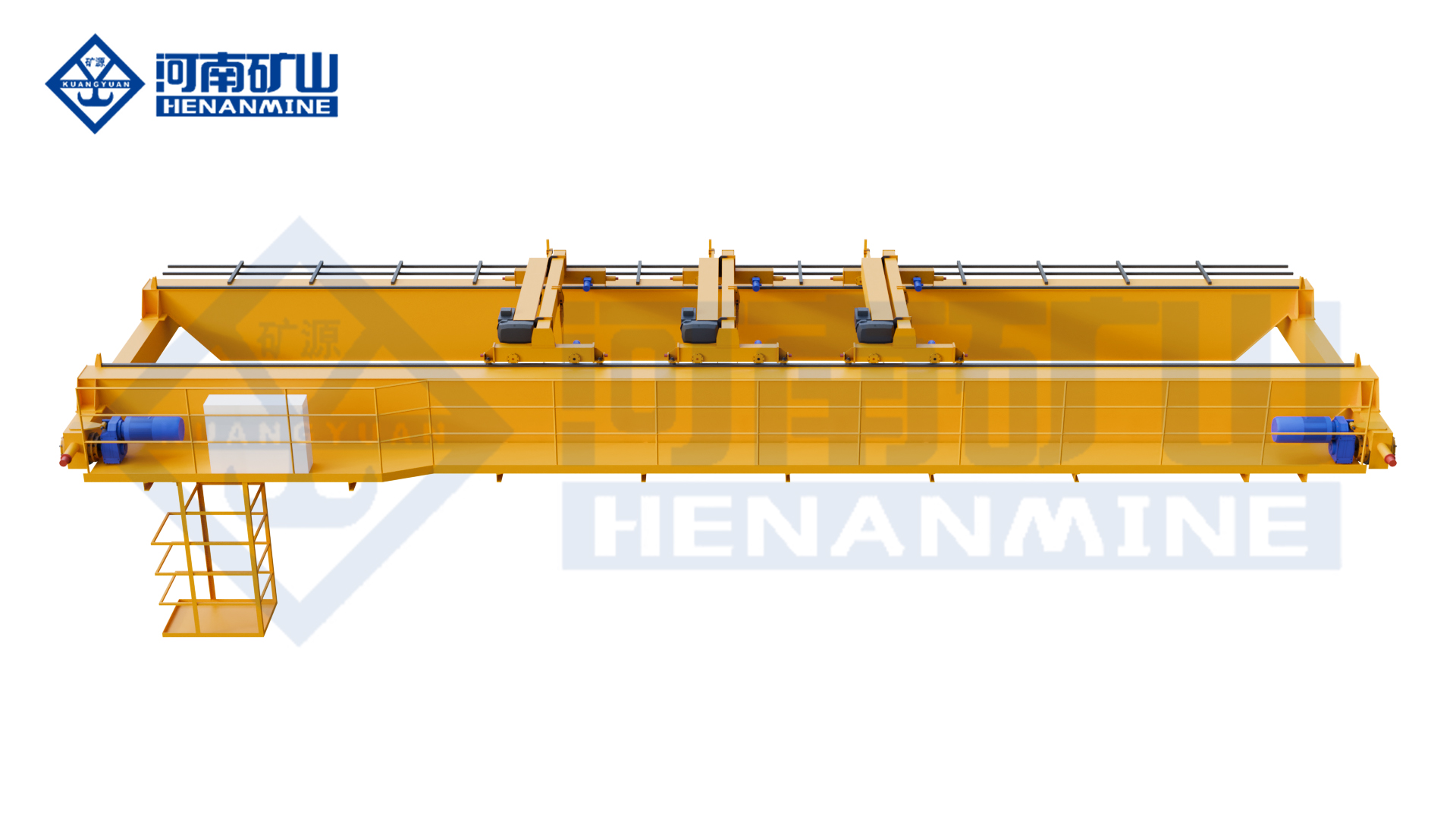
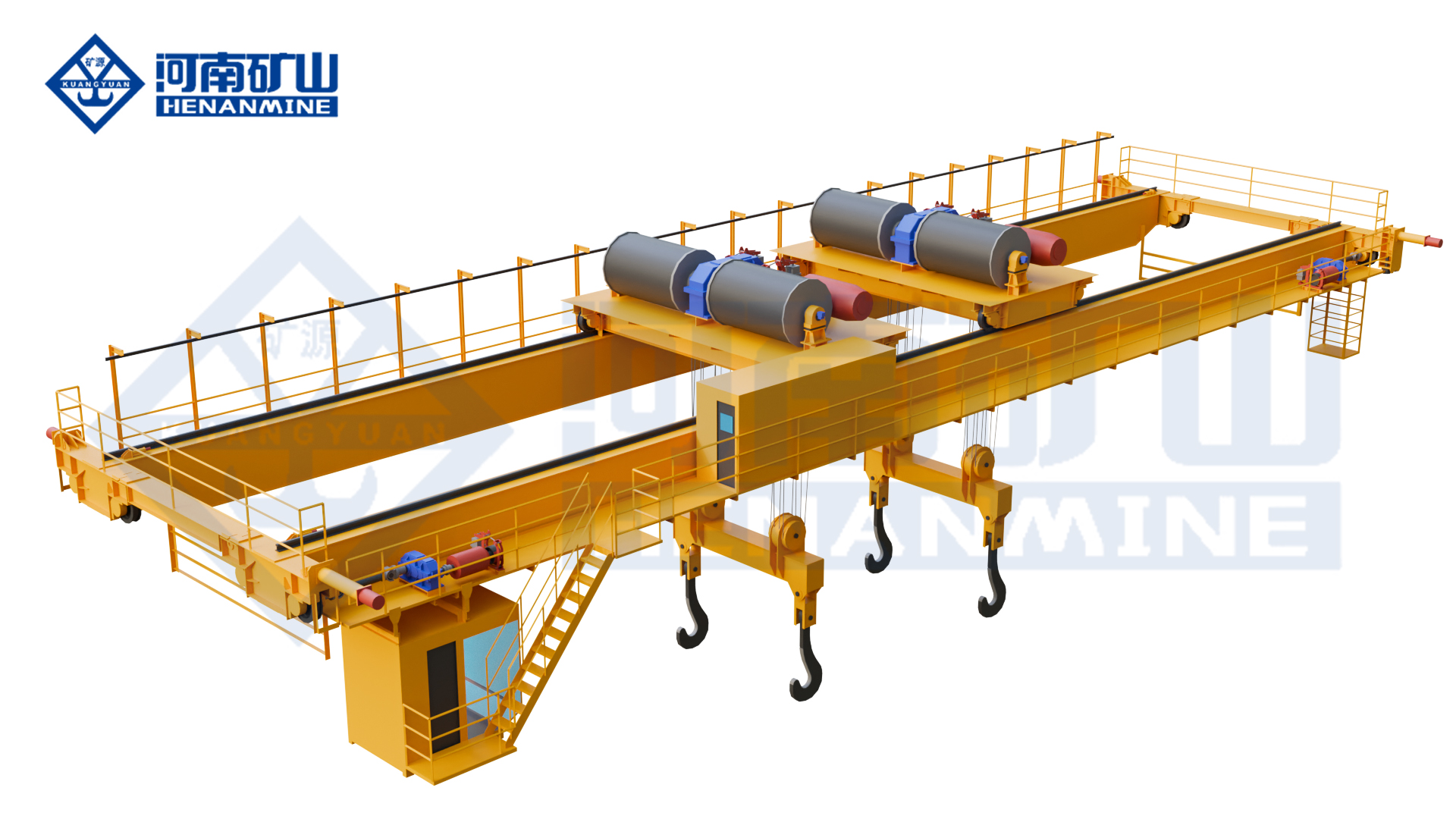
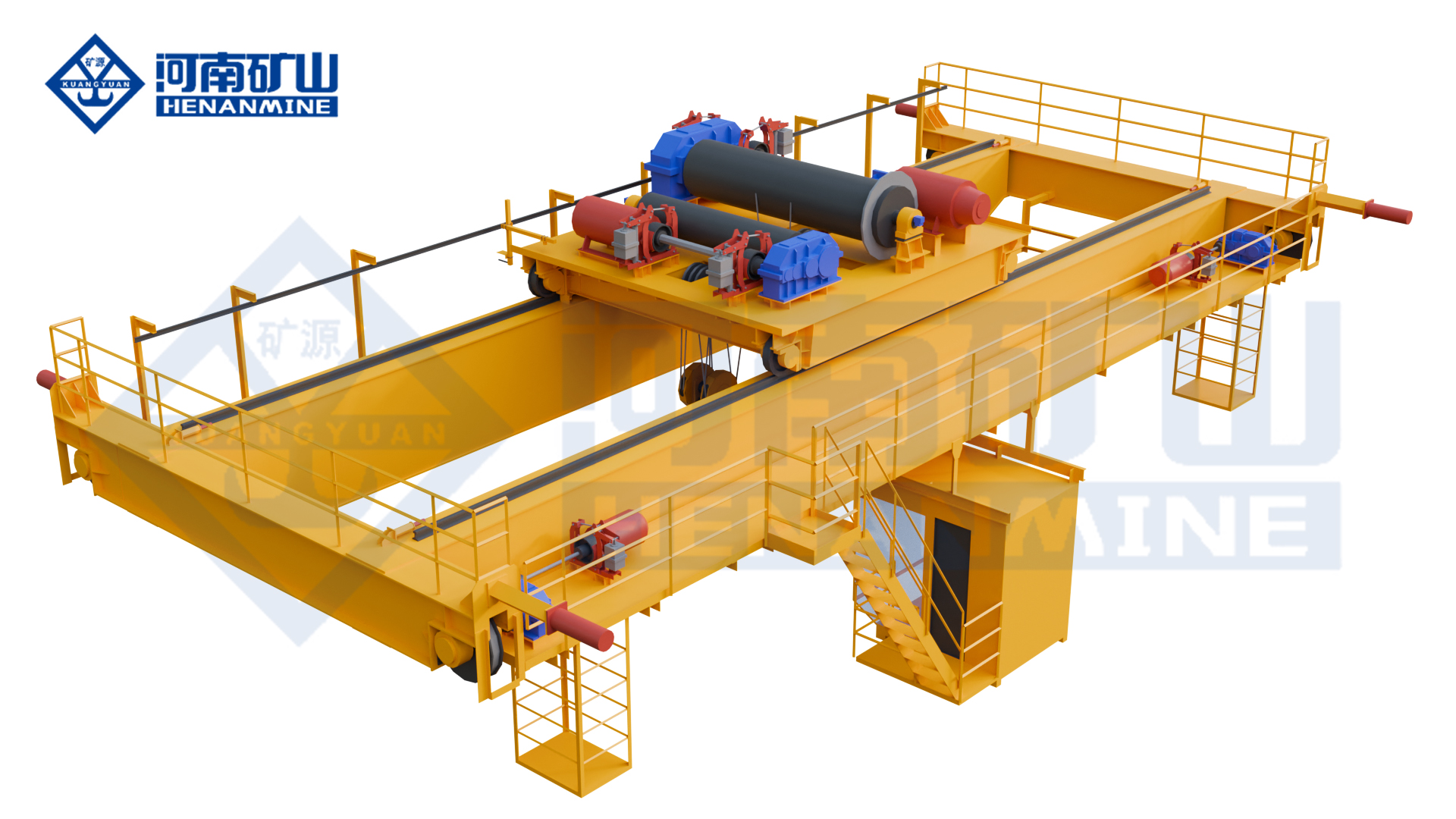
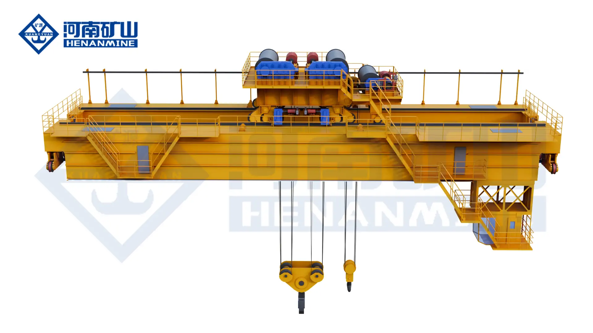
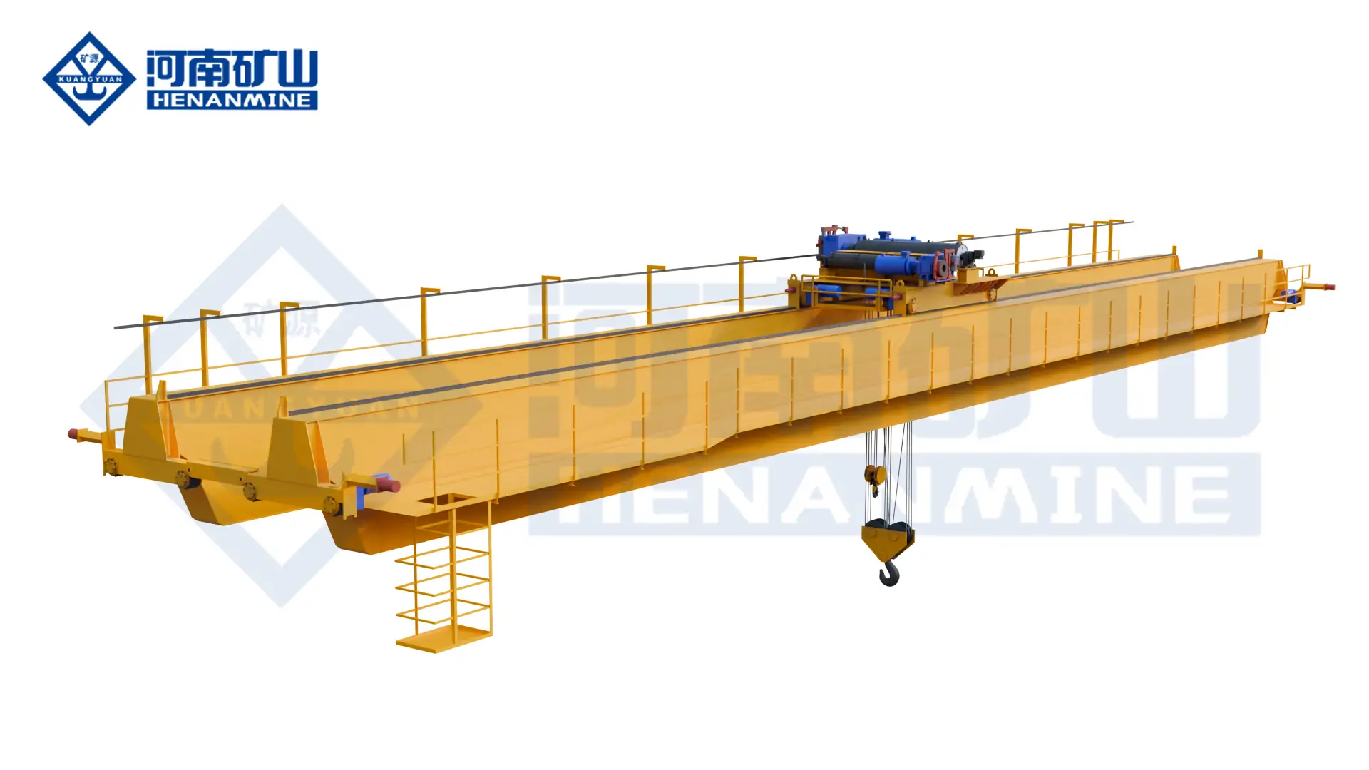
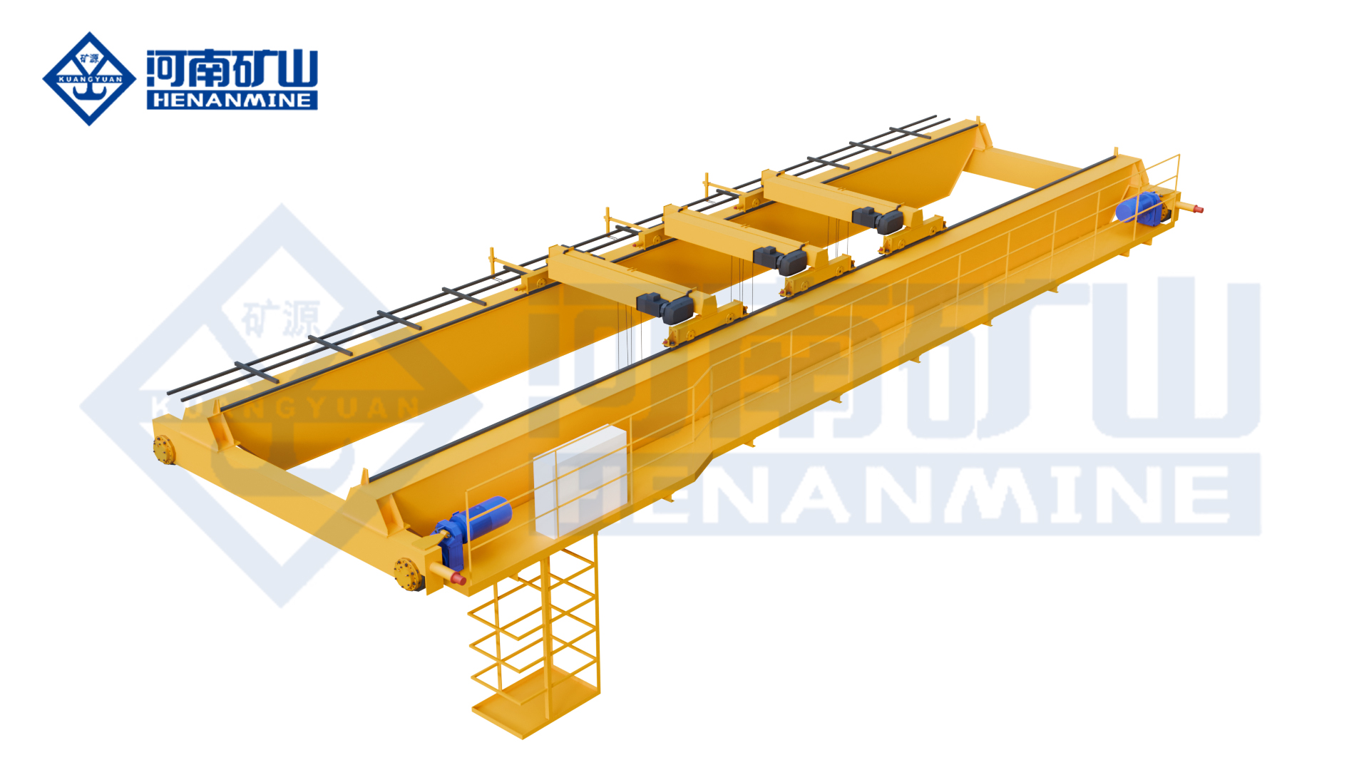
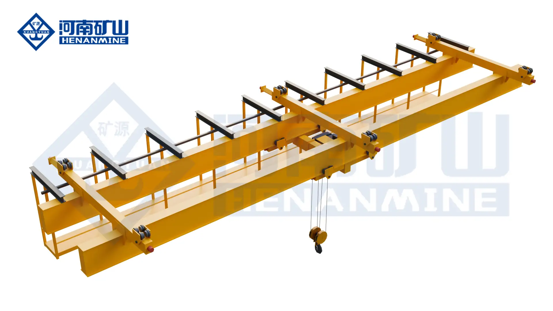
    Henan Mine Crane Multi Support Double Girder Underhung Crane
    Henan Mine Crane Multi Support Double Girder Underhung Crane
    Project planning notes

    Key points for this crane project.

    1. What an Aircraft Maintenance Crane Has to Do
    2. Where Cranes Work in an Aviation Facility
    3. Crane Configurations for Aviation Maintenance
    Read the technical guide

    What an Aircraft Maintenance Crane Has to Do

    An aircraft maintenance crane lifts aircraft components in hangars, MRO facilities and component backshops — engines on and off pylons, landing gear, flight control surfaces, APUs, wheels, brakes, seats, galleys and tooling. What defines these systems is not maximum tonnage but the combination the aviation environment creates: expensive and delicate loads, tight vertical space, wide bays, docking structures that steal the volume above the aircraft, and a cost of downtime that turns every maintenance hour into schedule pressure.

    Engine work shows the requirement in its purest form. A large turbofan arrives as an assembly with its cradle, transport stand or quick engine change kit, and the suspended weight lands well above the bare engine figure. The crane must lower it onto the pylon at a controlled crawl speed, hold position without drift while it is aligned, and set it down without shock — cycle after cycle, on aircraft worth more than the hangar around them. The same discipline applies to landing gear, flap tracks and tail components that are long, flexible or awkward to support.

    The hangar itself constrains the machine. Roof heights are fixed, tail and dock structures occupy the working volume, and maintenance docks, platforms and scaffolding stand in the path a workshop crane would normally ignore. Suspended underhung systems that ride on the roof steel, low-headroom hoist designs that recover every centimetre of hook height, and multi-support runs that carry one crane line across wide, irregular bays exist precisely because aviation buildings rarely leave room for anything else.

    Henan Mine Crane supplies aircraft maintenance cranes as engineered packages: the suspended, low-headroom or double girder crane platform, the hoist and control system with its precision functions, the suspension or runway interface to the hangar structure, safety functions and documentation — configured against the aircraft types and facility geometry of the specific operator.

    Where Cranes Work in an Aviation Facility

    Engine Removal and Installation

    Engines travel with cradles, QEC kits and transport stands, so the rated load is the full assembly. Micro-speed hoisting, stable holding and shock-free set-down onto the pylon decide both the schedule and the risk of the engine change.

    Landing Gear and Flight Controls

    Gear assemblies, flap tracks, elevator and rudder components are heavy, long or cantilevered. Synchronised two-point lifting with controlled speed keeps them straight and unstressed through the whole removal path.

    Component Backshops

    Wheels, brakes, APUs, seats, galleys and test equipment move through repair cells and benches. Workstation and suspended systems place these loads exactly where the work stands needs them, at ergonomic heights.

    Dock-Side Structural Work

    Fuselage panels, doors and wing components are handled beside docking towers that occupy the hook’s natural path. Coverage, reach around docks and clearance planning matter as much as capacity in these bays.

    Paint and Composite Hangars

    Paint and composite shops add atmosphere and cleanliness constraints to every crane operating inside them. Enclosure class, surface finish and absence of dripping or contamination are specified with the environment in mind.

    GSE and Material Logistics

    Ground support equipment, tooling, containers and consumables flow between stores, staging areas and the aircraft. General bay cranes keep this logistics stream moving around the maintenance schedule.

    Crane Configurations for Aviation Maintenance

    The configuration follows the hangar before it follows the load. These are the platforms that aviation facilities actually build their lifting systems around, and where each one wins.

    Where the roof steel allows it, underhung and European-style suspended cranes are the backbone of aviation lifting. They hang from the building structure with no elevated runway steel, run at low height directly over the work, and place the hook in the station instead of above it. Multi-point suspension extends the same principle across wide or irregular bays, and multi-support double girder underhung systems carry one crane line along long production and hangar runs.

    Where a runway exists or heavier loads demand it, low-headroom single girder cranes recover hook height that standard designs lose to the hoist trolley — critical under hangar roofs — and double girder cranes take the heaviest assemblies, gear units and special tooling. Intelligent hoist cranes add closed-loop positioning, monitored lifting and dual braking for the highest-value loads in the facility.

    Whatever the platform, the aviation build centres on control quality: frequency inverter travel and hoisting with micro-speed steps for engine and component set-down, anti-sway behaviour for long lifts across the bay, and synchronised two-point handling for gear, tracks and long parts.

    Aircraft Maintenance Crane Selection Considerations

    Selection starts with the aircraft and the components actually handled in the facility, then works outward to the building. These parameters establish the specification a quotation must be built against.

    List every lift with its complete suspended weight — engine with cradle or QEC kit, gear assemblies, tooling. A large turbofan that weighs six tonnes bare can impose well over ten tonnes on the hook by the time it is rigged.

    Roof height, tail heights of the largest aircraft type, dock and platform positions, and the vertical distance from hook to hangar steel define which configurations are even possible. In aviation, headroom eliminates options before price does.

    Map every pick-up and set-down position against docks, scaffolding and the aircraft envelope. Wide or irregular bays are covered with multi-point suspension or multi-support runs instead of losing coverage to runway steel.

    Define the required creep speed for engine set-down, the holding behaviour under load, and the positioning tolerance at each station. These select between standard dual-speed and frequency-controlled hoisting with defined micro-speed ratios.

    Loads destined for open engine bays and composite work demand drip-free hoists, enclosed components, controlled surface finishes and wheels that run clean. Cleanliness is a specification item, not a housekeeping outcome.

    Cycles are moderate but the cost of failure is extreme — a crane out of service can hold an aircraft in the hangar. Mechanism classifications, brake redundancy and maintenance access are set for availability, not just load.

    Radio control for sight-line management, overload protection, limit functions, anti-sway and synchronised two-point lifting are specified per station. Where engines are involved, dual braking on the hoist belongs in the base specification.

    Load tests, documentation and acceptance criteria for the operator’s QA system, plus the suspension or runway interface, installation, commissioning and training scope — all assigned in writing before offers are compared.

    Hangar Crane Configurations Compared

    The right configuration covers the required positions at the required precision without spending headroom or roof steel capacity the hangar does not have to give.

    ConfigurationWhere It Fits BestHeadroom Demand
    European-style suspended craneBackshops, component cells, line stationsLowest — rides on roof steel
    Multi-point suspension craneWide or irregular hangar baysLow — suspension designed to the roof
    Multi-support double girder underhung craneLong hangar and production runsLow to moderate
    Low-headroom single girder craneBays where every centimetre of hook height countsRecovered — hoist beside the girder
    Double girder bridge craneHeavy assemblies, gear units, tooling, logistics baysHighest hook position, trolley on top
    Intelligent hoist craneHighest-value loads and repeatable precision liftsPer platform selected

    Aircraft Maintenance Crane Technical Specification Framework

    Henan Mine Crane maintains several crane families applied to aviation maintenance service. The ranges below support preliminary configuration and are not guaranteed combinations. Final capacity, span, lift, working class, speeds and wheel or suspension loads are confirmed on the approved technical schedule and general arrangement drawing, together with the hangar structure interface.

    Product FamilyPublished Span PositionLifting Height Position
    European-style electric single beam suspended craneSuspended track length by bayDefined by roof height
    Multi-point suspension craneWide or irregular bays by suspension designProject-defined by roof geometry
    Multi-support double girder underhung craneLong runs with multiple support pointsProject-defined
    Intelligent electric hoist overhead craneModel-specificModel-specific

    A capacity shown within one family does not confirm suitability at every span, lift or duty. Hangar steel verification, dock clearances and precision functions require project-specific calculation and interface definition.

    Hangar Structure and Building Interface

    In a hangar, the crane and the building are one system. These interface points decide which configurations are possible and what the project must include beyond the crane itself.

    Roof Steel Capacity

    Suspended systems hang the full crane and load from the hangar roof structure. Truss capacity, bracing positions and allowable deflection are verified before any suspension layout is fixed.

    Clearance to Aircraft and Docks

    Hook paths are mapped against the tallest aircraft tail, docking towers and platforms in the bay. The crane must reach every working position without crossing protected volumes.

    Runway Rails on Hangar Steel

    Top-running cranes need rails, wheel load verification and often local reinforcement of the hangar structure — work that belongs in the project scope, not in a surprise during installation.

    Power Feed and Control Positions

    Conductor or festoon systems are routed with isolation points and maintenance positions that do not interfere with dock movement or floor traffic, and control stations are placed for sight-line management.

    Precision, Control and Safety Functions

    Aviation lifting is decided at the last centimetre of the move. These control functions are what separate a hangar crane from a general workshop crane of the same tonnage.

    Micro-Speed Hoisting

    Frequency-controlled hoisting with defined creep steps lowers engines and assemblies at a controlled crawl and holds position without drift — the core requirement of engine set-down.

    Synchronised Two-Point Handling

    Gear assemblies, flap tracks and long components travel level on two synchronised hoists, preventing the bending and twisting that a single hook point would impose.

    Anti-Sway and Smooth Travel

    Anti-sway behaviour and stepless travel control keep long lifts across wide bays calm and predictable, protecting both the load and the aircraft parked below it.

    Radio Control and Safety Functions

    Radio control keeps the operator at the load with full sight lines, while overload protection, limit functions and dual hoist braking belong in the base specification for engine work.

    Engineering and Supply Scope for Aviation Lifting Projects

    An aviation lifting project typically combines several systems in one facility: suspended and workstation cranes through the backshops and line stations, low-headroom or multi-support cranes covering the hangar bays, and a double girder crane for the heaviest assemblies and tooling. Henan Mine Crane plans these projects around a common engineering baseline — one control behaviour, one spare parts standard and one documentation set across every crane family in the facility.

    A complete supply definition states the crane platform and hoist specification, the control and precision functions required at each station, the suspension or runway interface to the hangar structure, the safety functions with their acceptance criteria, the overload and load test regime, and the delivery, installation, commissioning and training responsibilities. Documentation is aligned with the operator’s maintenance and quality system so every acceptance step is evidenced.

    Standard configurations are typically delivered within 30 to 45 days after drawing approval. Engineered systems with synchronisation, anti-sway or multi-support runs are delivered on confirmed project schedules agreed before production starts.

    Aircraft Maintenance Crane Price Reference

    Current market positions for Chinese-manufactured crane equipment, expressed as indicative ranges. An equipment price covers the crane ex-works; an installed project adds suspension or runway steel, power systems, freight, duty, installation and commissioning.

    Crane ScopeWhat Moves the Number
    Workstation bridge craneCovered rail length, bridge count, hoist grade
    Underhung / suspended craneSuspension length, track layout, hoist specification
    Low-headroom single girder craneHeadroom design, span, speed control level
    Double girder crane (engine and heavy assembly)Span, duty, micro-speed ratios, dual braking
    Precision control and synchronisationMicro-speed, anti-sway, sync hoists, monitoring
    Freight, duty and installationDestination, installation scope, local certification

    Normalize every quotation to the same boundary before comparing — rated capacity including rigging, span, hook height within the actual hangar clearance, speed control and micro-speed ratios, safety functions, suspension or runway interface, installation, testing and documentation.

    Quote Information and Frequently Asked Questions

    A complete enquiry should state the aircraft types served, every lift with its complete suspended weight, hangar dimensions and roof steel condition, dock layout, required precision functions, power supply, destination and the required supply boundary.

    Aircraft and Load Data

    Aircraft types, engine and component weights with cradles and QEC kits, landing gear assemblies, and the heaviest complete suspended load in the facility.

    Hangar and Geometry Data

    Roof height and steel capacity, bay spans, dock and platform positions, tail heights, travel lengths and every pick-up and set-down position the cranes must cover.

    Precision and Function Data

    Required creep speeds, holding behaviour, positioning tolerances, synchronised handling needs and the safety functions required for engine and component work.

    Commercial and Site Data

    Voltage and frequency, destination and Incoterm, installation responsibility, required certifications and documentation, spares level and requested delivery schedule.

    What crane is used for aircraft maintenance?

    Suspended and underhung cranes for backshops and line stations, low-headroom single girder cranes for height-restricted hangar bays, multi-support runs for wide or long coverage, and double girder cranes for engines, gear and heavy tooling — with micro-speed control wherever components are set down precisely.

    What capacity does an engine change need?

    The rating follows the complete suspended assembly, not the bare engine. A large turbofan of around six tonnes can impose well over ten tonnes on the hook once its cradle, QEC kit or transport stand is rigged, so the crane is rated to that total.

    Why is low headroom so important in hangars?

    Hangar roof heights are fixed, and docks, platforms and aircraft tails consume the volume below them. Every centimetre the hoist takes above the hook is a centimetre the maintenance process loses, so underhung and low-headroom designs exist to give it back.

    Can one crane system cover the whole hangar bay?

    Wide and irregular bays are covered with multi-point suspension or multi-support underhung runs, where one crane line travels along the bay on several suspension points. The layout is engineered against the roof steel and the dock positions, not against a catalogue span.

    What is the delivery time?

    Standard configurations are typically delivered within 30 to 45 days after drawing approval. Systems with synchronised handling, anti-sway or multi-support runs run on confirmed project schedules agreed before production starts.

    Related Crane Products for Aviation Maintenance

    Product selection follows the aircraft types, hangar geometry, precision requirements and load schedule of each facility. Each linked model represents a separate configuration platform.

    European Style Electric Single Beam Suspended Crane

    Roof-suspended platform for component backshops and line stations with smooth travel and low overall height.

    Multi-Point Suspension Crane

    Suspension crane covering wide or irregular hangar bays with hook reach directly at the working position.

    Multi-Support Double Girder Underhung Crane

    One crane line on multiple suspension points, carrying long hangar and production runs without elevated runway steel.

    Electric Single Beam Crane for Low Clearance

    Low-headroom crane recovering hook height in bays where the roof, docks and aircraft tails set the limit.

    Double Girder Bridge Crane

    Heavy-duty platform for engines, gear units, special tooling and logistics bays with the highest hook position.

    Intelligent Electric Hoist Overhead Crane

    Monitored hoist crane with closed-loop positioning and dual braking for the facility’s highest-value loads.

    Get a Maintenance Crane System Engineered for Your Hangar

    Send the aircraft types, load schedule, hangar dimensions and dock layout and receive a configured proposal with the crane platform, precision functions, building interface, documentation and delivery schedule for your facility.

    Discuss the crane arrangement for your project.

    Some maintenance tasks require several lifting points or coordinated movements. Define the approved handling arrangement, load distribution and operating boundaries so the complete crane system can be assessed for the task. Share the load, available drawings, working cycle and site conditions with Henan Mine Crane so the required configuration and supply boundary can be discussed.

    Related crane configurations

    Multi Support Double Girder Underhung Crane

    View product parameters
    Lifting capacity: 3 – 40 tSpan: 10 – 80 mLifting height: 6 – 30 m

    Use a multi-support double-girder underhung arrangement for wide-span working areas and large components. The building supports, lifting coverage and load distribution are designed together.

    Three Trolley Electric Hoist Crane

    View product parameters
    Lifting capacity: 1 – 32 tSpan: 7.5 – 31.5 mLifting height: 6 – 30 m

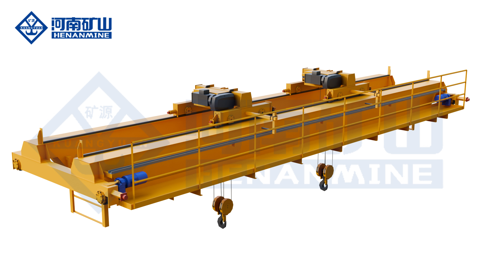
    Coordinate three electric-hoist trolleys for long components or several workshop lifting positions. Define hook loads, trolley spacing and permitted individual or combined movements.

    Updated 2026 · Henan Mine Crane
  • Hangar Crane Layout: Aircraft Clearance and Maintenance Access

    Hangar Crane Layout: Aircraft Clearance and Maintenance Access

    Selection guide

    Hangar Crane Layout: Aircraft Clearance and Maintenance Access

    A hangar layout should show the aircraft envelope and required service positions. Check the hook paths, roof interfaces and nearby equipment so the proposed crane arrangement provides useful maintenance coverage.

    Henan Mine CraneSelection guide · Updated 2026Crane selection, project scope and operating requirements
    Henan Mine Crane Multi Support Double Girder Underhung Crane
    Henan Mine Crane Multi Support Double Girder Underhung Crane
    Project planning notes

    Key points for this crane project.

    1. Use a coordinated hangar drawing
    2. Mark the required hook positions
    3. Resolve roof and runway interfaces
    Read the technical guide

    Use a coordinated hangar drawing

    Begin with a plan and cross-section showing the aircraft positions to be served. Include the relevant aircraft envelopes, door openings, roof structure, service installations and fixed maintenance equipment. Mark the drawing revision so crane and building teams work from the same layout.

    Show alternative parking or maintenance positions as separate operating cases. A hook that reaches a point on an empty floor may not have a usable path when an aircraft, platform or open door occupies that position.

    Mark the required hook positions

    For each task, identify the pickup and placement points and the highest and lowest required hook levels. Include the lifting fixture and component envelope when determining usable clearance.

    Ask the supplier to show side approaches, end approaches and excluded zones on the proposed crane drawing. Measure coverage from the actual hook position rather than from the bridge centreline or the outside dimensions of the building.

    Resolve roof and runway interfaces

    An underhung or multi-support arrangement requires an engineered support interface. Provide support locations, available beam details and the information needed by the building designer. Request configuration-specific reactions and connection requirements from the crane supplier.

    Compare roof services and crane travel on the same cross-section. Check the space used by ducts, lighting, sprinklers and other installations, including access needed to maintain them. Treat any structural suitability decision as part of the building engineering scope.

    Reserve clearance for moving systems

    Consider door travel, maintenance platform positions and other cranes through their full intended movement. Show where equipment can be parked and whether it changes the usable lifting area.

    Where travel routes intersect, identify how separation is managed and which party specifies the relevant interface. Avoid relying on a visual gap in a drawing without accounting for equipment envelopes and operating conditions.

    Close the layout before releasing detailed work

    Maintain a list of unresolved dimensions and assign responsibility for site measurement or design confirmation. Record the accepted hook-coverage drawing with the building interface documents.

    Send Henan Mine Crane the coordinated plan, cross-sections and task positions. A layout review can then focus on actual access constraints and useful service coverage instead of assuming the whole hangar floor is equally accessible.

    Discuss the crane arrangement for your project.

    A hangar layout should show the aircraft envelope and required service positions. Check the hook paths, roof interfaces and nearby equipment so the proposed crane arrangement provides useful maintenance coverage. Share the load, available drawings, working cycle and site conditions with Henan Mine Crane so the required configuration and supply boundary can be discussed.

    Related crane configurations

    Multi Support Double Girder Underhung Crane

    View product parameters
    Lifting capacity: 3 – 40 tSpan: 10 – 80 mLifting height: 6 – 30 m

    Use a multi-support double-girder underhung arrangement for wide-span working areas and large components. The building supports, lifting coverage and load distribution are designed together.

    European Style Electric Single Beam Suspended Crane

    View product parameters
    Lifting capacity: 1t – 10tSpan: 7.5m – 28.5mLifting height: 6m – 20m

    Use a European-style electric-hoist suspension crane for overhead handling beneath a supported runway. Coordinate compact lifting geometry, travel control and building clearances with the workshop layout.

    Updated 2026 · Henan Mine Crane

  • Overhead Crane System Planning: Connect the Equipment and Facility

    Overhead Crane System Planning: Connect the Equipment and Facility

    Selection guide

    Overhead Crane System Planning: Connect the Equipment and Facility

    A crane system includes the interfaces that allow the equipment to work in the building. Coordinate the lifting task, runway, power supply and operating area before fixing the equipment specification and project scope.

    Henan Mine CraneSelection guide · Updated 2026Crane selection, project scope and operating requirements
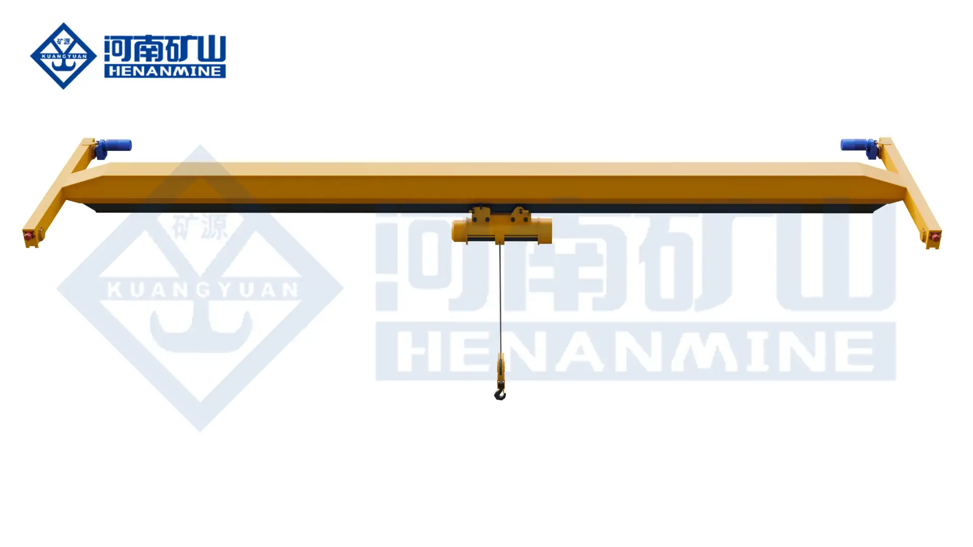
    Henan Mine Crane Single-Girder Bridge Crane
    Henan Mine Crane Single-Girder Bridge Crane
    Project planning notes

    Key points for this crane project.

    1. What Is an Overhead Crane System?
    2. Complete Overhead Crane System Components
    3. Overhead Crane System Configurations
    Read the technical guide

    What Is an Overhead Crane System?

    An overhead crane system is a coordinated material-handling installation that moves a suspended load vertically, laterally across a bridge and longitudinally along a runway. The term covers more than the visible bridge crane. It includes the hoist or trolley, bridge girders, end carriages, travel drives, runway interface, power supply, control equipment, protective devices and technical documents required for safe operation.

    System performance is determined by the interaction of these elements. A correctly selected hoist cannot compensate for an undersized runway, insufficient hook height, unsuitable working class or poorly defined power arrangement. Equally, a strong bridge does not establish production capability unless travel speeds, attachment, controls and operating coverage match the material flow.

    A complete project specification therefore begins with the maximum gross suspended load, load dimensions, handling route, lifts per hour, operating shifts, span, lifting height, headroom, building structure, environment and acceptance requirements. Rated capacity is only one input. Two cranes with the same tonnage can require different structures, mechanisms and project scopes when duty and operating conditions differ.

    Standard workshop systems normally use an electric wire-rope hoist on a single girder. Higher capacities, wider spans, demanding service, improved hook height or process attachments can require a double-girder bridge with an engineered trolley. Underhung and freestanding systems solve building or floor-layout constraints, while metallurgical, grab, magnetic, explosion-proof and automated cranes address process-specific risks.

    Complete Overhead Crane System Components

    Every component belongs to a continuous load and control path. Procurement documents should identify the responsible party for each item instead of assuming that a quoted bridge crane automatically includes the runway, building steel, incoming power, installation or load test.

    The bridge and hoist determine basic lifting motion, but runway geometry governs travel quality and wheel loading. Electrification powers the moving equipment. Controls coordinate motion, protection and operating modes. The below-hook device connects the crane to the actual load. Inspection and handover records establish the approved configuration for commissioning and future maintenance.

    01 · Bridge Structure

    One or two girders, end connections, end carriages, wheels, buffers and required platforms form the travelling bridge. Span, deflection, fatigue duty and wheel reactions control the structural design.

    02 · Hoist or Trolley

    Chain hoists support lighter localized handling; wire-rope hoists serve common industrial cranes; engineered winch trolleys support heavy, high-duty or process applications.

    03 · Runway Interface

    Rails, runway beams, brackets, columns, end stops and foundations transfer vertical and horizontal crane forces into the building or independent support structure.

    04 · Power and Electrification

    Incoming isolation, conductor bars, festoon cables, cable reels, trolley power and grounding are selected from travel length, speed, environment and maintenance access.

    05 · Controls and Safety

    Pendant, radio, cabin or PLC control works with brakes, limits, overload protection, emergency stop, alarms, anti-collision and application-specific interlocks.

    06 · Load-Handling Device

    Hooks, lifting beams, C-hooks, magnets, grabs, clamps and vacuum devices change suspended weight, geometry, electrical demand, control logic and operating risk.

    Overhead Crane System Configurations

    Single-Girder Top-Running System

    An electric hoist travels below one bridge girder while end carriages run on rails above the runway. This is a cost-controlled starting point for general manufacturing, assembly, warehouse and maintenance service.

    Double-Girder Top-Running System

    A hoist trolley runs on or between two girders. The arrangement supports higher capacity, longer span, improved hook height, greater bridge stiffness, service platforms and demanding duty.

    Single-Girder Underhung System

    The bridge runs beneath suspended runway beams. It preserves floor space and can improve end approach where the roof or supporting structure is verified for crane reactions.

    Multi-Support Underhung System

    Several suspended runway lines support a long bridge across wide facilities. Henan Mine Crane product families include multi-support solutions for large industrial and aircraft-related buildings.

    Freestanding Bridge Crane System

    Independent columns and runway beams carry crane forces without relying on the existing building frame. Foundations, aisle layout, vehicle movement and future expansion control the layout.

    Process and Automated System

    Metallurgical, grab, magnetic, hazardous-area or PLC-controlled cranes integrate dedicated attachments, redundancy, sensing, interlocks, positioning and plant communication.

    These values describe different product families rather than one universal specification; final parameters follow approved project data.

    Selection Considerations

    System selection should follow the production task and building constraints. The following inputs determine the bridge arrangement, hoist or trolley, travel mechanisms, runway reactions, control functions and commercial boundary.

    Record maximum payload, normal payload, center of gravity, dimensions, lifting points, rigging and every below-hook component included in gross suspended load.

    Define rail-center span, runway length, pickup and placement positions, end approach, side approach, hook path and restricted zones.

    State lowest pickup, highest placement, rail elevation, roof obstructions, load height, rigging depth and required maintenance clearance.

    Provide lifts per hour, load spectrum, full-load frequency, travel distances, operating shifts, annual hours and consequence of downtime.

    Identify existing or new runway steel, support spacing, rail data, building reactions, floor or foundation condition and structural responsibility.

    Specify hoist, trolley and bridge speeds, low-speed range, acceleration, VFD requirements, anti-sway, positioning accuracy and synchronized operation.

    Declare temperature, dust, humidity, corrosion, heat, washdown, cleanroom level, gas or dust classification and other abnormal exposure.

    Define destination, voltage, governing requirements, documentation language, inspection stages, installation scope, test weights and acceptance authority.

    Overhead Crane Systems Compared

    System ConfigurationLifting ArrangementTypical ApplicationPrimary Advantage
    Single-girder top runningElectric wire-rope hoist below one girderGeneral workshop and warehouse handlingLower self-weight, simpler structure and controlled acquisition cost
    Double-girder top runningHoist trolley on or between two girdersHeavy loads, wider spans and demanding productionHigher stiffness, better hook height and service access
    Single-girder underhungHoist below a bridge suspended from runway beamsFacilities requiring clear floor space and close end approachNo floor columns when the building can carry the runway
    Freestanding bridge systemTop-running or underhung bridge on independent steelworkExisting buildings without suitable crane supportDefined load path independent of the main building frame
    Workstation enclosed-track systemLight bridge and trolley on low-resistance enclosed trackRepetitive light-load assembly and ergonomic handlingEasy movement and localized process coverage
    Process or automated systemEngineered trolley or hoist with specialized attachment and controlsSteel, foundry, bulk, waste, hazardous or automated productionPurpose-built productivity, safety and plant integration

    Configuration principle: the lowest-cost structure should only be selected after capacity, span, headroom, duty, building reactions and process risk have been satisfied. System suitability takes priority over nominal tonnage.

    Technical Specification Framework

    A comparable quotation requires one controlled data sheet. Each proposal should state the design basis, assumptions and exclusions so that differences in structure, duty, controls and project scope remain visible.

    Specification ItemRequired Project DataEngineering BasisProcurement Control
    Rated capacityMaximum gross suspended load at the hook or attachmentPayload, rigging and below-hook device includedCapacity basis approved before design release
    Crane configurationSingle or double girder; top running, underhung or freestandingSelected from load, span, headroom, duty and support structureGeneral arrangement identifies the full load path
    Span and travelRail-center span and total runway lengthPickup zones, placement zones and approaches definedBuilding width is not substituted for crane span
    Lifting heightHook travel from lowest pickup to highest operating pointLoad height and rigging depth includedHighest hook and lowest hook shown on drawing
    Working classCrane and mechanism classifications stated separatelyEstablished from load spectrum and operating frequencyCapacity alone does not determine duty
    SpeedsHoist, trolley and bridge speeds with low-speed rangesAcceleration and deceleration match load stabilityProduction cycle and positioning requirement verified
    Control methodPendant, radio, cabin, PLC or combined operating modesOperating station, travel directions and fallback mode definedInterface and responsibility matrix included
    Power supplyProject voltage, frequency, phases and control voltageIncoming point, conductor system and grounding identifiedSite and crane electrical boundaries separated

    Runway, Building and Headroom Integration

    The runway and supporting structure are part of the crane load path even when they are supplied by another contractor. Crane wheel loads, lateral forces, longitudinal forces, buffers, rail joints and conductor supports act on runway beams, brackets, columns and foundations. Approved reactions must reach the responsible structural engineer before building or runway fabrication is finalized.

    Top-running cranes place wheels on rails above the runway beams. Underhung cranes suspend end carriages from compatible beam flanges. Freestanding systems transfer forces through independent columns into foundations or a verified floor structure. Each arrangement creates different alignment tolerances, support loads, erection sequences and maintenance access requirements.

    Headroom must be checked on a dimensioned vertical section. Rail elevation, bridge depth, trolley or hoist geometry, highest hook position, load height, lifting attachment, roof bracing, services and maintenance-removal routes should appear together. A compact low-headroom hoist can recover usable lift, but the benefit should be measured against duty, accessibility and component standardization.

    Existing runways require more than a visual confirmation. Rail gauge, straightness, elevation, joints, clips, end stops, beam condition, support connections and historical loading should be reviewed. A heavier replacement crane or a higher duty cycle can increase wheel reactions even when rated capacity remains unchanged.

    Electrification, Controls and Safety Functions

    Runway Power Supply

    Insulated conductor bars suit long travel and regular operation; festoon systems suit defined cable-management layouts; cable reels solve selected travel and environmental conditions.

    Motion Control

    Contactors, soft starters or variable-frequency drives establish starting torque, acceleration, braking, low-speed positioning and mechanical stress on the crane and building.

    Operating Stations

    Pendant control provides direct local operation, radio control improves mobility and visibility, cabins serve selected process cranes, and PLC interfaces support automatic sequences.

    Hoisting Protection

    Overload limiting, upper and lower limits, service and holding brakes, rope guidance, hook safeguards and emergency stop are matched to the mechanism and risk assessment.

    Travel Protection

    End limits, buffers, rail sweeps, alarms and anti-collision functions reflect runway length, multiple-crane operation, restricted zones and plant traffic.

    Automation and Recovery

    Position feedback, anti-sway, load sensing, obstacle detection and plant communication require a defined safe state, manual recovery method and fault-diagnostic strategy.

    Molten metal, magnets, grabs, hazardous areas and unattended operation require dedicated risk controls beyond those used on a conventional general-service hook crane.

    Industrial Applications for Overhead Crane Systems

    Manufacturing and Assembly

    Moves raw material, machine components, fixtures and finished assemblies between machining, welding, inspection and dispatch stations. Positioning speed and hook approach often control productivity.

    Warehouse and Logistics

    Handles coils, plates, machinery and unit loads across storage bays. Attachment type, storage geometry, inventory logic and collision zones determine the system configuration.

    Steel Mill and Foundry

    Transfers ladles, billets, slabs, coils and hot material under high duty and elevated risk. Redundancy, heat protection, braking and process interlocks become central requirements.

    Bulk and Waste Handling

    Uses grab buckets for ore, coal, biomass, slag, aggregate or waste. Bulk density, grab volume, fill factor, cycle time and hopper geometry establish productive capacity.

    Power and Maintenance

    Supports turbine, generator, pump and transformer installation or overhaul. Infrequent operation can still require high reliability, precise slow speed and long-term maintainability.

    Hazardous and Controlled Areas

    Explosion-proof, cleanroom, insulated or corrosion-resistant systems use project-defined equipment protection, materials, enclosures and documentation for the declared environment.

    Project Case: Multi-Model Overhead Crane System for Special Steel Production

    A 3.2-million-ton premium special steel production base required an integrated crane fleet across steelmaking, refining, rolling and auxiliary operations. Henan Mine Crane delivered more than 30 core equipment units in one coordinated project package.

    Foundry cranes served molten-metal operations, rotating magnetic systems handled directional steel transfer, and smaller cranes supported auxiliary production and maintenance.

    The project demonstrates why an overhead crane system should be matched to process stages rather than standardized around one bridge design. Capacity, girder arrangement, trolley, attachment, working class, control method and safety functions changed with the handled material and production risk, while project engineering and delivery remained coordinated.

    Engineering, Supply, Installation and Acceptance

    A complete system purchase connects approved operating data to design, fabrication, inspection, packing, site execution and final handover. Drawings and reaction data should be approved before bridge or runway interfaces are released.

    Manufacturing records can include material identification, welding documentation, dimensional checks, mechanism data, electrical diagrams, coating records and factory test results. Site records can include rail alignment, torque checks, control settings, functional tests, load-test results and commissioning sign-off.

    Scope PackageTypical ContentRequired DefinitionCommercial Control
    Crane equipmentBridge girders, end carriages, wheels, hoist or trolley, travel drives, buffers and required access itemsApproved capacity, span, lift, duty and arrangementStructural fasteners and assembly items listed
    Electrical and controlsPanels, pendant or radio, VFDs, limits, alarms, crane wiring and moving electrificationVoltage, frequency, control method and enclosure ratingIncoming supply and runway feed assigned
    Runway and supportsRails, clips, beams, brackets, columns, stops and foundations where contractedTravel length, rail section, support spacing and reactionsBuilding and civil responsibility stated
    Documentation and testsDrawings, manuals, certificates, inspection records, electrical diagrams and packing documentsLanguage, approval stages and witness pointsFactory and site acceptance criteria agreed
    Logistics and site workExport packing, freight, unloading, erection, wiring, alignment and commissioning as contractedIncoterm, access, assembly area, labor and equipmentTaxes, permits and local resources allocated
    Final acceptanceFunctional checks, protective-device settings, rated-load test and operator familiarizationTest procedure, test weights and acceptance authorityHandover package and open items recorded

    Overhead Crane System Price and Total Project Cost

    System pricing changes with capacity, span, lift, duty, bridge arrangement, hoist or trolley, runway length, electrification, controls, building work, logistics and site service. Public international market positions support preliminary budgeting, but a binding proposal requires approved technical data and a defined delivery boundary.

    System Budget PositionTypical BasisItems Requiring Confirmation
    Light workstation crane systemShort-span enclosed-track or ergonomic handling system in published retail configurationsCapacity, bridge count, runway length, support steel, hoist, freight and installation
    Double-girder bridge crane equipmentHigher-duty bridge and trolley packageCapacity, span, platforms, runway reactions, installation and special controls
    Heavy, automated or process crane systemCustom structure, attachment, redundancy, automation or severe-duty protectionProcess cycle, hazard controls, plant integration, documentation and site acceptance

    Commercial comparison: capacity, span, lift, working class, speeds, controls, runway scope, electrification, documentation, freight, installation and testing must be normalized before prices are compared. An equipment-only figure should not be compared with an installed-system quotation.

    Indicative ranges are capital-planning positions rather than fixed Henan Mine Crane quotations. Currency, destination, material cost and local site conditions can materially change the final contract value.

    Quote Information and Frequently Asked Questions

    A complete request for quotation should contain enough information to select the system and divide project responsibility. The minimum data set includes maximum gross suspended load, normal load spectrum, load dimensions, attachment, span, runway length, lifting height, rail elevation, duty cycle, speeds, controls, environment, power supply, building information, destination, installation boundary and acceptance requirements.

    Load and Process Data

    Maximum and normal loads, dimensions, center of gravity, lifting points, attachment, lifts per hour, travel route and production consequence.

    Building and Coverage Data

    Span, runway length, rail elevation, headroom, columns, roof obstructions, existing runway information and required hook approaches.

    Operating and Control Data

    Working shifts, load spectrum, speeds, low-speed positioning, pendant, radio, cabin, automation, anti-sway and plant interfaces.

    Commercial and Site Data

    Destination, Incoterm, voltage, local requirements, inspection authority, installation resources, test weights and required commissioning scope.

    What is included in a complete overhead crane system?

    A complete contracted system can include bridge structure, hoist or trolley, end carriages, travel drives, runway electrification, controls, protective devices, rails or runway steel, documentation, installation and testing. The exact boundary must be listed in the quotation.

    Does an overhead crane price include the runway?

    Runway beams, rails, columns, brackets and foundations are separate unless expressly included. Existing runway suitability also requires structural and alignment verification.

    When is a double-girder system required?

    Double-girder construction becomes relevant when capacity, span, duty, hook height, bridge stiffness, trolley arrangement, maintenance access or process equipment exceeds a suitable single-girder basis.

    Can an overhead crane be installed in an existing building?

    Installation is possible when the building and runway can safely accept crane reactions and required clearances. Otherwise, reinforcement or an independent freestanding runway may be required.

    How is the required working class selected?

    Working class follows load spectrum, operating frequency, travel distances, shifts, annual hours and process consequence. Rated capacity alone does not establish mechanism or structural duty.

    What controls are available?

    Common options include pendant, radio remote and cabin control. Variable-frequency drives, PLC automation, anti-sway, positioning and plant communication are available when justified by the operating process.

    How long does installation take?

    Duration depends on bridge size, runway readiness, building access, assembly method, electrical scope, local labor, permits and testing. A site-readiness review is required before a dependable schedule is issued.

    Which documents support final acceptance?

    The handover package can include approved drawings, reaction data, electrical diagrams, manuals, inspection records, component data, test results, commissioning settings and recommended spare-parts schedules.

    Related Overhead Crane Products

    Product selection follows the approved load, duty, building and process requirements. Each crane is configured within one complete system boundary.

    Single-Girder Overhead Crane

    Cost-controlled electric-hoist bridge for general manufacturing, assembly, warehouse and maintenance service.

    Double-Girder Overhead Crane

    Two-girder platform for higher capacity, longer span, demanding duty and process equipment.

    Underhung Overhead Crane

    Suspended bridge arrangement for compatible runway beams and verified building support.

    Explosion-Proof Overhead Crane

    Dedicated lifting system configured for a formally defined hazardous gas or dust area.

    Metallurgical Overhead Crane

    Heavy-duty process crane developed for hot-metal and severe metallurgical service.

    Intelligent Grab Overhead Crane

    Grab-bucket and intelligent-control configuration for repetitive bulk-material handling.

    Submit the maximum gross load, span, lifting height, runway length, duty cycle, building information, control requirements, power supply, operating environment, destination and required project boundary. Henan Mine Crane will prepare a configuration-based technical and commercial proposal.

    Discuss the crane arrangement for your project.

    A crane system includes the interfaces that allow the equipment to work in the building. Coordinate the lifting task, runway, power supply and operating area before fixing the equipment specification and project scope. Share the load, available drawings, working cycle and site conditions with Henan Mine Crane so the required configuration and supply boundary can be discussed.

    Related crane configurations

    Single-Girder Bridge Crane

    View product parameters
    Lifting capacity: 1–20 tSpan: 7.5–31.5 mLifting height: 6, 9, 12, 18, 24 or 30 m; capacity-dependent

    Use an LDA single-girder bridge and electric hoist for general workshop material handling. Select the lifting capacity, runway geometry and hoist duty around the building and load.

    LH Electric Hoist Double Girder Crane

    View product parameters
    Lifting capacity: 3, 5, 10, 16, 20 tSpan: 10.5–31.5 mLifting height: 6, 9, 12 or 18 m

    Use an LH double-girder bridge with an electric-hoist trolley for workshop lifting, assembly and maintenance. Match the hoist arrangement to the suspended load, hook travel and available building space.

    Updated 2026 · Henan Mine Crane

  • Overhead Crane Supplier Proposals: Compare Industrial Project Scope

    Overhead Crane Supplier Proposals: Compare Industrial Project Scope

    Selection guide

    Overhead Crane Supplier Proposals: Compare Industrial Project Scope

    Industrial suppliers should respond to a common brief covering load, geometry and working duty. Review model-specific documents and the responsibilities for delivery, installation and handover before comparing commercial terms.

    Henan Mine CraneSelection guide · Updated 2026Crane selection, project scope and operating requirements
    Henan Mine Crane Single-Girder Bridge Crane
    Henan Mine Crane Single-Girder Bridge Crane
    Project planning notes

    Key points for this crane project.

    1. What Should an Overhead Crane Supplier Provide?
    2. Core Capabilities of Industrial Overhead Crane Suppliers
    3. Compare Overhead Crane Supplier Models
    Read the technical guide

    What Should an Overhead Crane Supplier Provide?

    An overhead crane supplier may be a direct manufacturer, a system integrator, a regional distributor or a turnkey contractor. The commercial label alone does not establish capability. The required role depends on whether the project covers only crane equipment or also includes runway steel, electrification, freight, erection, commissioning, load testing and statutory acceptance.

    For a standard workshop crane, a packaged electric hoist and single-girder bridge may satisfy the operating task. Steel production, foundry, bulk handling, hazardous areas and automated material flow require deeper process engineering. The supplier must understand the handled material, operating environment, attachment, crane duty, control philosophy and consequence of interruption before finalizing the structure and mechanisms.

    A complete proposal identifies the design basis, rated capacity, span, lifting height, duty classification, speeds, power supply, controls, safety functions, wheel loads, documentation, testing and supply boundary. A price without these items cannot support a reliable comparison because omitted runway, installation or acceptance work can exceed the apparent equipment-price difference.

    Core Capabilities of Industrial Overhead Crane Suppliers

    01 · Crane Selection and Engineering

    Translate payload, dimensions, duty, building geometry and operating route into the correct bridge, hoist or trolley, end carriages, controls and safety package.

    Evidence to confirm: Dimensioned general arrangement, technical data sheet, wheel loads and declared design basis.

    02 · General Overhead Crane Portfolio

    Supply single-girder, double-girder, top-running and underhung systems with chain hoists, wire-rope hoists or open-winch trolleys for approved capacities and duties.

    Evidence to confirm: Product data tied to span, lift, duty, mechanism and runway arrangement.

    03 · Process Crane Capability

    Configure foundry, grab, magnetic, insulated, explosion-proof, cleanroom and automated cranes around the handled material and operating hazard.

    Evidence to confirm: Comparable project evidence and a process-specific safety and control description.

    04 · Manufacturing and Inspection

    Control materials, welding, machining, assembly, coating and electrical panels through approved drawings and an agreed inspection plan.

    Evidence to confirm: Material records, welding documentation, dimensional checks, test reports and release records.

    05 · Export and Site Coordination

    Plan shipping divisions, packing, freight interfaces, site access, runway information, erection method, commissioning and acceptance responsibilities.

    Evidence to confirm: Packing list, shipping drawing, installation information and responsibility matrix.

    06 · Lifecycle Support

    Provide manuals, spare-parts data, maintenance schedules, troubleshooting support and modification information for the installed crane configuration.

    Evidence to confirm: Final documentation set, critical-spares schedule and defined technical-support channel.

    Compare Overhead Crane Supplier Models

    Supplier ModelTypical ScopeCommercial AdvantagePrimary Control Point
    Direct crane manufacturerDesign, fabrication, mechanisms, controls and factory testingTechnical control, customization and direct factory communicationLocal erection, permits and statutory work may require regional partners
    Manufacturer with local installerFactory equipment plus regional erection and commissioningClear division between equipment engineering and local executionInterface responsibility must be contractually assigned
    Turnkey system integratorCrane, runway, electrification, installation and acceptance coordinationOne broad project interface and integrated scheduleEquipment origin, design ownership and subcontract scope require visibility
    Regional distributorStandard cranes, hoists, parts and local serviceLocal response, familiar regulations and installation resourcesCustomization and factory engineering may pass through another company
    Equipment traderCommercial coordination for equipment from third-party factoriesCan consolidate purchasing or logisticsEngineering authority, quality control and post-delivery accountability require close verification
    Used-equipment dealerExisting crane, hoist or components with condition-dependent scopeLower initial equipment cost in selected casesFit, fatigue history, documents, controls, runway compatibility and recertification create uncertainty

    Supplier selection rule: assign responsibility for design, runway interface, installation, commissioning and acceptance before comparing price. Unassigned interfaces become project risk.

    Match Supplier Experience to the Crane Application

    Industry / ApplicationHandled MaterialStarting Crane TypeCritical Engineering Data
    General manufacturingMachine parts, tools, weldments and assembliesSingle- or double-girder hook craneHoist duty, positioning, hook approach and building fit
    Warehouse and logisticsCoils, plates, unit loads and stored equipmentHook, clamp, magnet or automated craneStorage geometry, inventory logic, collision zones and throughput
    Steel mill and foundryLadles, hot metal, billets, coils and platesHeavy-duty metallurgical or process craneHeat, duty, redundancy, braking, attachment and load-path risk
    Bulk and waste handlingOre, coal, biomass, slag, aggregate or wasteGrab crane with manual or automated controlBulk density, grab volume, fill factor, cycle time and hopper interface
    Hazardous productionLoads within classified gas or dust areasExplosion-proof overhead craneZone, group, temperature class, protection concept and documentation
    Automated productionRepeatable loads moving between fixed process pointsPLC-controlled process craneAccuracy, anti-sway, sensors, interlocks, plant communication and recovery mode

    Load attachment is part of the crane system. A hook supports rigged loads, a grab handles loose bulk material, a magnet handles compatible ferrous products, and a lifting beam controls long or multi-point loads. Changing the attachment changes suspended weight, dynamic behavior, duty, electrical demand and risk controls; attachment selection should therefore precede final crane sizing.

    Technical Selection and Quotation Framework

    Every shortlisted supplier should quote against one measurable project data sheet. Missing information creates different assumptions and prevents a valid commercial comparison. The following matrix defines the minimum technical basis and the corresponding supplier deliverable.

    Data GroupProject InformationSupplier DeliverableProcurement Control
    Maximum gross suspended loadPayload plus hook block, beam, magnet, grab, clamp, sling and every suspended componentRated capacity, mechanism sizing and load-case statementNo capacity margin is inferred from payload alone
    Span and working coverageRunway rail centers, bridge travel, pickup points, placement points and side approachesGeneral arrangement with span and hook approachesBuilding width is not substituted for crane span
    Lift and available headroomLowest pickup, highest placement, rigging depth, rail elevation and roof obstructionsDimensioned vertical section and highest-hook positionHoist geometry is confirmed before bridge fabrication
    Duty and load spectrumLifts per hour, average load, full-load frequency, shifts, annual hours and travel distancesCrane and mechanism classification with motor and brake basisCapacity and duty are evaluated independently
    Runway and buildingRail size, beam data, support spacing, alignment condition and building reactionsMaximum and minimum wheel loads plus horizontal forcesBuilding engineer receives approved reactions
    Speeds and controlsHoist, trolley and bridge speeds, low-speed positioning, pendant, radio, cabin or automationMotor, VFD, brake and control descriptionOperating mode and emergency fallback are stated
    Environment and hazardTemperature, dust, humidity, corrosion, washdown, heat, clean area or hazardous classificationEnclosures, materials, coating and protection scheduleGeneric outdoor or explosion-proof labels are not accepted
    Power and acceptanceVoltage, frequency, phases, destination rules, inspection authority and test requirementsElectrical data, inspection plan and document scheduleFactory and site acceptance boundaries are written

    Safety, Standards and Control Requirements

    The governing technical basis depends on destination, crane type and application. Contract documents should identify the applicable crane, electrical, structural and occupational requirements instead of combining incompatible clauses without hierarchy. Safety functions must correspond to the risk assessment and operating method.

    Load and Hoist Protection

    Overload limiting, upper and lower limits, brakes, rope or chain guidance, hook protection and low-speed control are selected for the hoisting mechanism and duty.

    Travel Protection

    End limits, buffers, rail sweeps, warning devices, emergency stops and anti-collision functions reflect runway length, traffic and multiple-crane operation.

    Electrical Protection

    Isolation, overcurrent protection, phase monitoring, earthing, enclosure rating, conductor arrangement and cable management match the plant supply and environment.

    Process-Crane Safeguards

    Molten metal, magnets, grabs, hazardous areas and automated operation require dedicated redundancy, monitoring, interlocks or operating restrictions.

    Inspection and Test Planning

    Drawing reviews, material checks, welding inspections, functional tests, protective-device settings and witness points should be agreed before manufacturing.

    Operator and Maintenance Access

    Platforms, walkways, clearances, isolation points and component-removal routes are evaluated with the building and maintenance strategy.

    Runway, Building and Headroom Responsibility

    An overhead crane is only one part of the load path. Vertical wheel loads, horizontal forces, buffers, conductor equipment and maintenance access interact with runway beams, columns, foundations and the building frame. The crane supplier should issue approved reactions and rail requirements; the responsible structural party should verify the supporting system and connection details.

    Top-running cranes place wheels on rails above the runway beams. Underhung cranes suspend end carriages from the lower flanges of compatible runway beams. A freestanding runway transfers crane loads through independent columns and foundations. Each arrangement creates different reactions, alignment tolerances and erection requirements.

    Headroom should be verified on a dimensioned building section. Rail elevation, bridge depth, hoist or trolley position, highest hook, load height, rigging depth, roof bracing and service-clearance zones must be shown together. A lower equipment price has little value when the final hook height cannot complete the required lift.

    Project Case: Crane Fleet for a Special Steel Production Base

    A 3.2-million-ton premium special steel base required a coordinated crane fleet rather than one universal bridge-crane design. Henan Mine Crane supplied more than 30 core equipment units serving steelmaking, refining, rolling and auxiliary production stages.

    Foundry cranes served molten-metal operations, rotating electromagnetic equipment handled directional steel transfer, and smaller cranes supported auxiliary tasks.

    The procurement value lies in application separation. Each production stage received a crane structure, lifting mechanism, attachment, duty and control package matched to the material and hazard. The case demonstrates the capability expected from an industrial overhead crane supplier: process study, multi-type engineering, manufacturing coordination and project-wide delivery.

    Engineering Deliverables and Quality Records

    Supplier capability should be demonstrated through project documents and controlled manufacturing records. Required evidence should be listed before order placement because inspection scope affects engineering, production access, schedule and price.

    Design Package

    General arrangement, wheel loads, hook approaches, electrical demand, component schedule and declared design basis.

    Structural Records

    Material identification, approved welding procedures, welder qualifications, dimensional inspection and specified examination records.

    Mechanism Data

    Motor, gearbox, brake, drum, rope or chain, wheel, bearing, limit and protective-device information for the selected duty.

    Electrical Documents

    Single-line diagram, schematics, terminal data, control narrative, I/O schedule and configured drive parameters.

    Inspection and Testing

    Inspection plan, witness points, functional checks, brake and limit verification, protective-device setting and contracted load testing.

    Handover Package

    Manuals, maintenance schedule, spare-parts list, test records, commissioning information and final approved drawings.

    Project Delivery, Installation and Lifecycle Support

    Engineering Approval

    Confirm technical data, drawings, wheel loads, electrical demand, control description, deviations, document schedule and approval milestones before production release.

    Factory Production and Testing

    Track material, fabrication, mechanism assembly, electrical-panel checks, protective functions, inspections, witness points and release documentation.

    Packing and International Delivery

    Define shipping divisions, corrosion protection, packing, labels, lifting points, container or project-cargo method, trade term and delivery boundary.

    Runway and Site Readiness

    Verify runway span, elevation, rail alignment, building capacity, incoming power, erection access, shutdown windows and available assembly space.

    Installation and Commissioning

    Assign erection, alignment, electrical termination, parameter setting, functional checks, load testing, statutory inspection and operator training.

    Maintenance and Spare Parts

    Provide inspection schedules, lubrication data, wear limits, critical spares, electrical drawings and technical support matched to the installed configuration.

    Overhead Crane Price and Supplier Scope

    The following September 2026 market figures support preliminary budgeting. They are not fixed Henan Mine Crane prices. Published values use different regional labor, installation and equipment boundaries, so every proposal must be normalized before commercial ranking.

    ConfigurationItems Requiring Confirmation
    Workstation bridge systemSupport steel, hoist, electrification, freight, assembly and floor work
    Ceiling-hung or freestanding monorailHoist, support structure, track length, curves, installation and testing
    Double-girder bridge craneOpen-winch trolley, platforms, runway, automation, special environment and testing
    Heavy-duty or automated process craneAttachment, redundancy, plant interfaces, civil work, commissioning and production shutdowns

    Commercial normalization: compare crane equipment, runway, electrification, packing, freight, installation, commissioning, load testing, training, spare parts and acceptance as separate line items. A lower equipment figure does not establish a lower installed project cost.

    Information Required for an Overhead Crane Supplier Quote

    A complete request for quotation reduces assumptions and makes proposals technically comparable. Building drawings, load sketches and operating-cycle data should accompany the following information whenever available.

    Load and Material

    Maximum and typical load, dimensions, weight distribution, center of gravity, lifting points, attachment, temperature and any hazardous characteristics.

    Capacity and Duty

    Required rated capacity, lifts per hour, average load, full-load frequency, shifts, annual operating hours and expected service life.

    Span and Building

    Runway rail centers, building width, column spacing, rail elevation, runway beam and rail data, roof obstructions and available headroom.

    Lift and Motion

    Lowest pickup, highest placement, lifting height, rigging depth, bridge travel, required speeds, low-speed positioning and target accuracy.

    Controls and Power

    Pendant, radio or cabin operation, voltage, frequency, phases, conductor arrangement, VFDs, anti-sway, automation and plant communication.

    Environment and Destination

    Indoor or outdoor location, temperature, dust, humidity, corrosion, hazardous-area data, destination country and governing requirements.

    Inspection and Documents

    Drawing approval, calculations, material records, witness points, factory testing, site testing, language and third-party inspection.

    Commercial Boundary

    Delivery location, trade term, runway scope, installation, commissioning, load-test responsibility, training, spare parts and required schedule.

    Overhead Crane Supplier FAQ

    What is the difference between an overhead crane supplier and manufacturer?

    A manufacturer designs and fabricates crane equipment. A supplier may be a manufacturer, distributor, integrator or contractor. The proposal should identify the legal manufacturer, design authority, equipment origin and party responsible for project performance.

    Which documents should be requested before placing an order?

    The pre-order package should include technical data, general arrangement, wheel loads, electrical demand, supply boundary, deviation list, document schedule, inspection plan, delivery schedule and commercial terms.

    How can overseas overhead crane suppliers support local installation?

    A practical structure combines factory engineering and remote or site supervision with a qualified local installation team. Responsibilities for lifting equipment, labor, permits, rail alignment, electrical work and acceptance should be assigned in writing.

    Should the lowest overhead crane price determine the supplier?

    Supplier comparison should use equal equipment, duty, runway, controls, documentation, freight, installation and testing boundaries. Omitted site work or inadequate duty can create a higher total project cost.

    How is the required crane duty established?

    Duty follows load spectrum, lifts per hour, travel distances, operating shifts, annual hours, speed and process consequence. Rated tonnage alone cannot determine motor, brake, bearing or structural fatigue requirements.

    Can one supplier provide both the crane and runway?

    Yes, when the contracted scope includes runway steel or an independent support structure. Structural responsibility, foundations, building interfaces, local calculations and installation tolerances must still be clearly assigned.

    What should factory acceptance cover?

    The agreed plan may cover document review, dimensions, mechanisms, electrical panels, motor operation, brakes, limits, warning devices, protective functions and available no-load or simulated tests before shipment.

    How should spare parts be specified?

    Critical spares should reflect the installed motors, brakes, drives, contactors, encoders, limits, ropes, wheels and controls. Part numbers, quantities, storage requirements and recommended commissioning spares should be listed.

    Which crane type suits a standard workshop?

    A single-girder electric wire-rope-hoist crane is a common starting point for moderate general-duty handling. Span, lift, headroom, duty, hook approach and runway reactions determine final suitability.

    When is a process-crane supplier required?

    Process-crane capability is required when molten metal, grabs, magnets, hazardous areas, automated production, high duty or critical loads create requirements beyond a conventional packaged-hoist bridge crane.

    Related Overhead Crane Products

    Compare product families after the load, duty, building and process requirements have been defined. Each configuration is finalized through project-specific engineering.

    Single-Girder Overhead Crane

    Cost-controlled electric-hoist bridge for general manufacturing, assembly and maintenance.

    Double-Girder Overhead Crane

    Two-girder platform for higher capacity, longer span, demanding duty and process equipment.

    Underhung Overhead Crane

    Suspended bridge arrangement for compatible runway beams and verified building support.

    Explosion-Proof Overhead Crane

    Dedicated lifting system for a formally defined hazardous gas or dust area.

    Metallurgical Overhead Crane

    Heavy-duty process crane developed for hot-metal and severe metallurgical service.

    Intelligent Grab Overhead Crane

    Grab-bucket and intelligent-control configuration for repetitive bulk-material handling.

    Discuss the crane arrangement for your project.

    Submit the application, maximum gross load, span, lifting height, duty, runway information, power supply, controls, operating environment, destination country and required project boundary. Henan Mine Crane will prepare a technical configuration and commercial quotation.

    Related crane configurations

    Single-Girder Bridge Crane

    View product parameters
    Lifting capacity: 1–20 tSpan: 7.5–31.5 mLifting height: 6, 9, 12, 18, 24 or 30 m; capacity-dependent

    Use an LDA single-girder bridge and electric hoist for general workshop material handling. Select the lifting capacity, runway geometry and hoist duty around the building and load.

    LH Electric Hoist Double Girder Crane

    View product parameters
    Lifting capacity: 3, 5, 10, 16, 20 tSpan: 10.5–31.5 mLifting height: 6, 9, 12 or 18 m

    Use an LH double-girder bridge with an electric-hoist trolley for workshop lifting, assembly and maintenance. Match the hoist arrangement to the suspended load, hook travel and available building space.

    Updated 2026 · Henan Mine Crane

  • Overhead Crane Hoists: Capacity, Headroom and Working-Cycle Selection

    Overhead Crane Hoists: Capacity, Headroom and Working-Cycle Selection

    Selection guide

    Overhead Crane Hoists: Capacity, Headroom and Working-Cycle Selection

    The hoist arrangement influences hook reach and operation within the bay. Define the complete suspended load, required lifting range and duty so the proposed mechanism can be checked within the crane's structural envelope.

    Henan Mine CraneSelection guide · Updated 2026Crane selection, project scope and operating requirements
    low headroom overhead crane hoist in an industrial workshop
    low headroom overhead crane hoist in an industrial workshop
    Project planning notes

    Key points for this crane project.

    1. What Is an Overhead Crane Hoist?
    2. Overhead Crane Hoist Types
    3. Compare Overhead Crane Hoist Configurations
    Read the technical guide

    What Is an Overhead Crane Hoist?

    An overhead crane hoist is the powered lifting mechanism that raises and lowers the load on a bridge crane. The hoist normally includes a lifting motor, brake, gearbox, rope drum or load chain, sheaves where applicable, hook block, limits and electrical controls. A trolley carries the hoist across the bridge, while the bridge travels along the runway to provide three-axis load movement.

    The correct purchase may be a replacement hoist for an existing crane, a hoist-and-trolley assembly for a new bridge, a pre-engineered component kit or a complete fabricated crane. These scopes are not interchangeable. A replacement requires verified girder, rail, wheel, power and control interfaces; a complete crane also requires bridge structure, end carriages, electrification, runway data and commissioning requirements.

    Rated capacity alone does not determine suitability. Lift height, headroom, hook approaches, duty spectrum, lifting speed, reeving, load geometry, operating environment and applicable regulations influence the final design. Henan Mine Crane establishes these inputs before confirming a wire-rope hoist, chain hoist, compact trolley or engineered winch arrangement.

    Overhead Crane Hoist Types

    01 · Electric Wire-Rope Hoist

    The principal choice for industrial bridge cranes requiring longer lifts, stable hook travel and medium to high operating duty. Rope reeving, drum capacity, motor thermal rating and brake selection are matched to the load spectrum rather than capacity alone.

    02 · Electric Chain Hoist

    A compact option for lighter capacities, shorter lifts and service or workstation duties. Chain-bag clearance, chain wear, duty rating, trolley fit and inspection access must suit the bridge arrangement and working environment.

    03 · Low-Headroom Hoist

    Positions the hoist body beside or between the girder profile to improve available hook height. It is selected where roof clearance is limited, but the complete trolley envelope, end approaches and maintenance access still require dimensional approval.

    04 · Double-Girder Hoist Trolley

    Travels on rails above or between two girders and supports greater capacity, lift or duty than a typical underslung monorail hoist. The trolley may carry one hoist, main and auxiliary hoists or coordinated lifting mechanisms.

    05 · Multi-Hoist Crane System

    Uses two or three hoists or trolleys for long loads, staged maintenance and coordinated positioning. Individual capacities, total permitted load, spacing, simultaneous-motion rules and load sharing are defined in the control philosophy.

    06 · Special-Environment Hoist

    Explosion-protected, corrosion-resistant, clean, dust-resistant or metallurgical configurations are engineered for the classified area and process risk. A standard hoist with isolated upgraded parts is not automatically suitable for a special environment.

    Compare Overhead Crane Hoist Configurations

    The preferred configuration follows the load, frequency, building envelope and crane structure. The comparison below establishes an initial direction; final selection requires an approved duty and interface review.

    Hoist ConfigurationBest Matched ToCrane InterfacePrimary Advantage
    Chain HoistLight production, service bays and compact workstationsPush, geared or motorized trolley on a suitable beamCompact construction and straightforward servicing
    Standard Wire-Rope HoistGeneral manufacturing, assembly and warehouse handlingSingle-girder monorail trolley or supported trolley arrangementBalanced capacity, speed, lift and industrial duty
    Low-Headroom Wire-Rope HoistExisting or low-roof workshops requiring greater hook heightOffset trolley arranged around the girder profileImproves usable lift without raising the runway
    Double-Girder Hoist TrolleyHigher capacity, longer lift or medium-heavy production dutyTop-running trolley on bridge railsHigher structural reserve and better hook approaches
    Dual or Multi-Hoist SystemLong products, rolls, beams and coordinated maintenance liftsTwo or more hoists on one bridge or separate trolleysIndependent or synchronized pickup points
    Open-Winch TrolleySevere duty, very high capacity or process-critical liftingEngineered trolley with separate drum, drives and machinery deckMaximum customization, redundancy and maintainability

    Procurement boundary: a hoist is not a complete overhead crane. The bridge, end trucks, runway interface, electrification, controls, structural steel and site services must be listed separately in every commercial comparison.

    Match the Hoist to the Crane and Application

    A hoist should be selected from the handling cycle and installed geometry. General workshop loads may favor a compact single-girder wire-rope hoist, while long products may require two independently controlled hoists. Low-clearance buildings benefit from a side-mounted or between-girder trolley only after the full hook path and maintenance envelope have been checked.

    The load itself defines the below-hook equipment and operating behavior. Machined assemblies, dies, coils, maintenance components and bulk-material attachments create different centers of gravity, starting torque, positioning accuracy and side-load risk. The crane layout must keep the rope or chain vertical during normal lifting.

    Environmental data is part of the selection basis. Dust, humidity, corrosive vapor, washdown, outdoor exposure, high ambient temperature and classified hazardous areas affect enclosures, motors, brakes, cables, coatings and inspection intervals.

    Crane or ApplicationRecommended Starting PointCritical InputsEngineering Priority
    Single-girder top-running craneMotorized wire-rope hoist or chain hoist below the girderCapacity, flange or trolley interface, headroom, approach and dutyLow self-weight with verified girder and trolley compatibility
    Underhung bridge craneCompact hoist on an under-running bridgeRunway flange, suspension points, wheel loads and building reactionsControlled loads on the supporting roof or floor structure
    Double-girder overhead craneRail-mounted hoist trolley or engineered winch trolleyRail gauge, wheel base, hook approach, capacity, lift and dutyStable trolley support and service access at higher duty
    Low-clearance workshopLow-headroom hoist or compact between-girder trolleyRoof obstructions, rail elevation, highest load point and hook dimensionMaximum usable lift with an approved maintenance envelope
    Long or flexible loadDual hoists or two-trolley synchronized systemPickup spacing, total mass, center of gravity and allowable twistDefined load sharing, speed matching and operating combinations
    Hazardous or process areaApplication-specific protected hoist and crane packageZone or division, gas or dust group, temperature class and process riskWhole-system compliance rather than component-level substitution

    Technical Selection and Specification Framework

    A procurement specification should state the operating requirement, not only a model designation. The following data establishes the mechanical, electrical and structural basis for a new hoist or replacement unit.

    Specification ItemInformation to ProvideEngineering DecisionCommercial Effect
    Rated load and attachmentMaximum lifted load plus hook, beam, magnet, grab or below-hook deviceCapacity, hook block, reeving, motor, brake and structural loadA heavier attachment can change the required hoist rating
    Lift and hook pathLowest pickup, highest set-down, floor-to-rail dimension and required reserveRope or chain length, drum capacity, reeving and limit positionsLong lift increases rope, drum, frame and shipping requirements
    Headroom and approachesRail elevation, roof obstructions, girder profile and required end approachesNormal, low-headroom or between-girder trolley arrangementCompact layouts require project-specific dimensional engineering
    Duty spectrumLifts per hour, average load, maximum-load frequency, shifts and annual hoursHoist duty class, motor thermal rating, brake duty and component lifeHigher utilization changes mechanisms and lifecycle cost
    Hoisting performanceMain and creep speeds, acceleration, positioning tolerance and cycle targetSingle, dual or variable speed; encoder and feedback requirementsPrecision and high speed affect drives, controls and braking
    Rope, chain and reevingLoad stability, hook travel, fleet angle and service accessibilityRope construction, falls, sheaves, drum or chain dimensionsReeving governs hook behavior, wear and maintenance access
    Trolley and girder interfaceBeam flange or rail section, gauge, wheel loads, bridge deflection and clearancesWheel profile, trolley frame, buffers and conductor arrangementReplacement fit must be verified from measurements and drawings
    Power and controlsVoltage, frequency, control voltage, pendant, radio, cab and plant interfacesContactors or VFDs, panel design, festoon and communicationsControls determine positioning, integration and documentation scope

    Safety, Controls and Hoist Protection

    Hoisting Brake System

    The brake is selected for motor torque, load, speed, duty and governing requirements. Brake release monitoring, manual release control or additional braking functions are defined where the risk assessment requires them.

    Upper and Lower Limits

    Operating and final limits prevent normal overtravel. Their positions are established from the actual reeving, hook block, drum and site clearances; a limit device is not used as a routine stopping control.

    Overload Protection

    A calibrated load-limiting or monitoring device prevents lifting beyond the permitted setting. Display, alarm, shutdown and data functions are coordinated with the crane control philosophy.

    Rope or Chain Monitoring

    Inspection access is provided for wire rope, drum, sheaves, anchorage, load chain, sprocket and chain guide. Removal criteria follow the applicable rules and manufacturer instructions.

    Controlled Travel and Anti-Sway

    Variable-frequency trolley and bridge drives provide smooth acceleration and deceleration. Position feedback, speed zones and anti-sway functions can be added where repeatability or load stability is critical.

    Emergency and Isolation Functions

    Emergency stop, main isolation, travel buffers, warning devices and lockout provisions are incorporated into the complete crane. The final arrangement follows the destination and site risk assessment.

    Hoisting Mechanism, Motion Control and Load Positioning

    In a wire-rope hoist, the motor and gearbox rotate the drum while the reeving system converts rope movement into controlled hook travel. The brake holds the suspended load when power is removed. Sheave arrangement, rope falls and drum capacity determine hook speed, stability and available lift. A chain hoist uses a load sprocket and calibrated chain but follows the same requirement for matched motor, brake, limits and trolley duty.

    Single- or dual-speed contactor control provides fixed operating speeds. Variable-frequency control permits adjustable acceleration, deceleration and creep motion, reducing load swing and supporting accurate placement. The selected control mode must remain compatible with brake timing, motor cooling and the required duty cycle.

    Multi-hoist systems require a defined operating matrix. The design states whether hoists may run independently, together or in synchronized mode; which combined loads are permitted; and how unequal loading, encoder disagreement or a drive fault is handled. No synchronization feature replaces correct rigging or an approved lifting plan.

    16 t Compact Hoist Trolley for a Low-Clearance Workshop

    The trolley machinery is arranged within the available girder envelope instead of relying on a conventional high-profile configuration.

    The engineering study begins with rail elevation, roof structure, obstruction zones, highest required load position, hook block dimensions and service access. Trolley wheel loads, rail gauge, bridge stiffness, lifting duty and end approaches are then checked as one arrangement. The objective is usable lift and maintainability, not minimum headroom in isolation.

    This configuration is suitable for capacity expansion or replacement projects only after the existing runway and building have been surveyed.

    Engineering Deliverables and Quality Records

    A technically comparable proposal includes interface drawings, performance data, inspection records and an acceptance plan. Contract deliverables are defined before manufacturing.

    Selection and Interface Package

    Approved data sheet, duty calculation, hoist and trolley arrangement, reeving diagram, hook approaches, wheel loads, girder or rail interface, power demand and equipment boundary.

    Manufacturing and Inspection Records

    Material and component certificates, welding and dimensional records where applicable, gearbox and brake checks, rope or chain records, electrical inspection and coating documentation.

    Testing and Handover Records

    Factory functional checks, direction and limit verification, brake test, overload-device setting, site load-test plan, commissioning reports, manuals, spare-parts list and training records.

    Review Henan Mine Crane manufacturing and quality capabilities →

    Installation, Commissioning and Lifecycle Planning

    Existing-Crane Survey

    For replacement work, record beam or rail dimensions, trolley gauge, hook approaches, power, controls, wheel loads, bridge condition and available access. Verify the supporting crane before ordering the hoist.

    Installation and Alignment

    Install trolley wheels, buffers, festoon, limits, rope or chain, hook block and controls under approved procedures. Check alignment, clearances, fasteners, lubrication and electrical protection before energization.

    Commissioning and Load Test

    Verify directions, brakes, limits, overload protection, pendant or radio functions and all crane motions. Conduct no-load, rated-load and statutory tests under the agreed acceptance plan.

    Inspection and Maintenance

    Establish inspections for brakes, rope or chain, drum, sheaves, hook, trolley wheels, gearbox, motors, limits, controls and structure. Intervals follow actual duty, environment and governing requirements.

    Overhead Crane Hoist Price and Supply Scope

    Hoist prices cannot be compared without capacity, lift, duty, headroom, speed, trolley arrangement, controls and included equipment. The following September 2026 North American retail benchmarks show how the commercial value changes between a hoist-only purchase and a crane component kit. They are market indicators, not fixed Henan Mine Crane quotations.

    Purchase ScopeTypical Included EquipmentItems Requiring Confirmation
    Complete custom crane or installed systemApproved hoist, trolley, bridge structure, end carriages, controls, electrification and contracted documentationRunway, freight, erection, commissioning, load testing, inspection and local works as defined

    Commercial evaluation should use one approved specification and a line-by-line inclusion, exclusion and responsibility schedule.

    Hoist Equipment

    Motor, brake, gearbox, rope or chain, drum or sprocket, hook block, trolley, limits and local controls.

    Crane Components

    Bridge girder, end carriages, travel drives, bridge panel, festoon, conductor system and access provisions.

    Engineering and Records

    Selection calculations, interface drawings, electrical documents, inspections, manuals and acceptance records.

    Delivery and Site Work

    Packing, freight, runway work, erection, power connection, commissioning, load test, training and spares.

    Information Required for an Overhead Crane Hoist Quote

    Complete project data allows the hoist, trolley and bridge interface to be priced on one defined basis. Existing equipment photographs should be accompanied by measured dimensions and available drawings.

    State whether the requirement is hoist only, hoist and trolley, component kit, complete crane or installed system.

    Provide maximum gross load, typical load, attachment mass, dimensions, center of gravity and pickup method.

    Specify rated capacity, lowest pickup, highest set-down, required lift and hook reserve.

    Identify single or double girder, top running or underhung, trolley rail or beam details and runway length.

    Provide span, rail elevation, roof clearance, obstructions, hook approaches and maintenance access.

    List lifts per hour, load spectrum, shifts, annual hours, required availability and expected design life.

    Define hoisting and travel speeds, creep speed, acceleration, positioning accuracy and synchronization needs.

    Confirm voltage, frequency, pendant, radio or cab operation, plant signals and preferred control architecture.

    State temperature, indoor or outdoor service, dust, corrosion, hazardous classification, destination and standards.

    Confirm delivery location, trade term, freight, runway, installation, testing, inspection, training and spares.

    Overhead Crane Hoist FAQ

    Is an overhead crane hoist the same as an overhead crane?

    The hoist raises and lowers the load. The trolley moves across the bridge, and the bridge travels along the runway. A complete crane combines all of these systems with controls and electrification.

    Should an overhead crane use a chain hoist or wire-rope hoist?

    Chain hoists commonly suit lighter, shorter-lift service. Wire-rope hoists generally suit longer lift, greater speed and industrial production duty. Final selection follows capacity, duty, headroom and maintenance requirements.

    What information is needed to replace an existing hoist?

    Provide capacity, lift, duty, power, controls, beam or trolley rail dimensions, wheel gauge, hook approaches, headroom, existing drawings and clear photographs. The supporting crane condition must also be verified.

    Can a larger hoist be installed on an existing crane?

    Not without engineering verification. Greater capacity or self-weight can exceed girder, end truck, runway, electrical or braking limits. The entire load path and supporting structure must be checked.

    What is a low-headroom overhead crane hoist?

    It is a compact hoist-trolley arrangement that places machinery beside or within the girder envelope to increase usable hook height. Actual benefit depends on the complete crane and building geometry.

    Can two overhead crane hoists lift one load?

    Yes, when the crane, controls, rigging and operating procedure are designed for the lift. Individual capacity, total load, spacing, synchronization, load sharing and fault response must be defined.

    Which hoist control is precise positioning?

    Variable-frequency control with suitable motor feedback and brake coordination provides smooth acceleration and creep speed. Required positioning tolerance, load behavior and duty determine the final control package.

    Does a crane kit include the bridge and runway steel?

    Not necessarily. Many kits include the hoist, trolley, end trucks, controls and festoon but exclude the main girder, runway, electrical feed, fabrication and installation. Every quotation must list inclusions.

    How is hoist duty selected?

    Duty is selected from the number of starts, operating time, load spectrum, lifting height, speed, shifts and environment. A frequently cycled partial load can require more duty than an occasional full-capacity lift.

    Related Overhead Crane Hoist Products

    Select the lifting mechanism and complete crane arrangement from the application, duty and building interface. Each product is configured to the approved project data.

    New Electric Hoist

    Compact modular electric hoist for industrial lifting and matched overhead crane applications.

    Intelligent Electric Hoist Overhead Crane

    Frequency-controlled overhead crane for workshops, assembly areas and warehouses.

    Double-Trolley Electric Hoist Crane

    Two-trolley system for long loads, coordinated lifting and flexible pickup spacing.

    Three-Trolley Electric Hoist Crane

    Multi-trolley bridge crane for independent stations and complex handling sequences.

    Explosion-Proof Electric Hoist Crane

    Application-specific crane package for correctly classified hazardous environments.

    Metallurgical Electric Hoist Crane

    Specialized electric-hoist crane for defined metallurgical handling and thermal conditions.

    Discuss the crane arrangement for your project.

    Submit the purchase scope, maximum load, lift, duty, speed, crane arrangement, beam or trolley-rail dimensions, available headroom, power supply, controls, environment, destination standards and delivery location. Henan Mine Crane will prepare a project-specific technical and commercial proposal.

    Related crane configurations

    LH Electric Hoist Double Girder Crane

    View product parameters
    Lifting capacity: 3, 5, 10, 16, 20 tSpan: 10.5–31.5 mLifting height: 6, 9, 12 or 18 m

    Use an LH double-girder bridge with an electric-hoist trolley for workshop lifting, assembly and maintenance. Match the hoist arrangement to the suspended load, hook travel and available building space.

    Double Trolley Electric Hoist Crane

    View product parameters
    Lifting capacity: 1+1 – 32+32 tSpan: 7.5 – 31.5 mLifting height: 6 – 30 m

    Lift long components or serve separate working positions with two electric-hoist trolleys on one bridge. Trolley spacing, load sharing and independent or coordinated operation are specified for the task.

    Updated 2026 · Henan Mine Crane

  • YX Metallurgical Bridge Crane

    YX Metallurgical Bridge Crane

    Overhead Cranes / Henan Mine Crane

    YX Metallurgical Bridge Crane

    Lift and turn material boxes with a YX metallurgical crane arrangement. The box interface, centre of gravity, turnover sequence and thermal conditions determine the lifting system.

    Lifting capacity5t – 50t
    Span7.5m – 35m
    Working classA6 – A7
    Technical specifications

    Define the total suspended load, duty and site conditions for your project.

    Technical specifications

    Check the load.
    Plan the configuration.

    Parameters and equipment options are matched to the application and confirmed in the technical proposal.

    Discuss your configuration
    Capacity5t – 50t
    Span7.5m – 35m
    Lifting height6m – 20m
    Working classA6 – A7
    Power supply380V/50Hz; 220-660V/50-60Hz
    ControlsPLC + HMI touch screen + WLK controller
    Lifting arrangementSingle/double trolley, bridge type

    Final parameters, dimensions, wheel loads and supply scope follow the approved project specification.

    Application & operation

    Matched to the handling task.

    Metallurgical material boxes

    Coordinate pickup, transfer and discharge of the specified process container.

    Process turnover

    Match lifting and turning movements to the box geometry and receiving station.

    Selection considerations

    Start with your operating conditions.

    01

    Load & lifting arrangement

    Specify box drawing, gross load, lifting points and centre of gravity. Include lifting-appliance weight and the required lifting positions.

    02

    Site & available space

    Provide pickup or receiving positions and turnover clearances. Coordinate the installation interfaces with the available site drawings.

    03

    Duty & control sequence

    Define turning sequence, load stability and thermal exposure. Identify the required movements and control interfaces in the enquiry.

    Configuration comparison

    Compare related lifting arrangements.

    Crane arrangementHandling configuration
    YX Metallurgical Bridge CraneLift and turn material boxes with a YX metallurgical crane arrangement. The box interface, centre of gravity, turnover sequence and thermal conditions determine the lifting system.
    Metallurgical Bridge CraneLift hot process loads with a YZD metallurgical bridge arrangement selected for the complete load and thermal conditions. Specify the lifting appliance, duty cycle and operating-protection requirements.
    Double Girder Casting CraneLift and transfer molten-metal ladles with a YZ casting crane configured for the full suspended load and casting process. Review ladle interfaces, thermal exposure and the operating sequence together.
    Quenching CraneMove heated workpieces through a defined quenching sequence with a process crane. Immersion, withdrawal, lifting geometry and thermal exposure determine the mechanism and controls.

    Operating protection & lifecycle support

    Plan beyond the equipment.

    01

    Operating protection

    Confirm overload protection, travel limits, brakes, emergency controls and the required process interlocks for the declared lifting task.

    02

    Installation & commissioning

    Agree runway reactions, structural interfaces, electrical connections, assembly, inspection and commissioning responsibilities before delivery.

    03

    Inspection & spares

    Plan inspection and maintenance of turnover connections, hoisting equipment and process interlocks. Agree service access, documentation and the required spare-parts scope.

    Questions before the order

    Clarify the details
    that shape the crane.

    What information is needed for a yx metallurgical bridge crane quotation?+

    Provide box drawing, gross load, lifting points and centre of gravity; pickup or receiving positions and turnover clearances; and turning sequence, load stability and thermal exposure. Include drawings and the project destination when available.

    What is required for the box-turning arrangement?+

    Provide the container drawing, all lifting interfaces and the complete turnover sequence. The proposed lifting points, load cases and control interlocks are defined around that process.

    What installation and support scope should be agreed?+

    Agree runway reactions, structural interfaces, electrical connections, assembly, inspection and commissioning responsibilities before delivery. Specify the documentation, training and spare-parts support needed for the project.

    Related equipment

    Explore the alternatives.

    Let’s discuss your project

    The right crane starts
    with your lifting task.

    Share box drawing, gross load, lifting points and centre of gravity, together with your site layout and operating cycle.

    info@hnksglobal.com
  • Overhead Crane Cost Planning: Separate Equipment and Destination Work

    Overhead Crane Cost Planning: Separate Equipment and Destination Work

    Selection guide

    Overhead Crane Cost Planning: Separate Equipment and Destination Work

    A project cost needs a consistent boundary between the equipment order and work at the site. Clarify runway, electrical supply, installation and support responsibilities before comparing supplier quotations.

    Henan Mine CraneSelection guide · Updated 2026Crane selection, project scope and operating requirements
    Henan Mine Crane Single-Girder Bridge Crane
    Henan Mine Crane Single-Girder Bridge Crane
    Project planning notes

    Key points for this crane project.

    1. How Much Does an Overhead Crane Cost?
    2. Indicative Overhead Crane Equipment Cost
    3. Selection Considerations
    Read the technical guide

    How Much Does an Overhead Crane Cost?

    Commercial basis: These ranges support preliminary capital planning and are not fixed Henan Mine Crane quotations. A formal proposal requires capacity, span, lifting height, duty, controls, environment, destination and a defined supply boundary.

    Indicative Overhead Crane Equipment Cost

    Factory-equipment budgets provide a starting point for feasibility studies. The same nominal capacity can produce a different cost when span, lift, duty, hoisting arrangement, component specification or operating environment changes.

    ConfigurationCommon Application BasisPrimary Cost Variables

    Factory-equipment ranges exclude runway structures, columns, foundations, freight, import charges, unloading, erection, site wiring and third-party acceptance unless expressly included. Detailed acquisition pricing is available in the overhead crane price guide.

    Selection Considerations

    Financial Planning Horizon

    A common evaluation period must be applied to equipment, operating expense, major service and residual value before alternative systems are compared.

    Load Spectrum and Work Cycle

    Average lifted load, maximum load, lifts per hour, travel distance and operating shifts determine mechanism duty, wear rate and service demand.

    Runway and Building Condition

    Runway capacity, alignment, columns, foundations, clearances and power distribution can represent a substantial share of the installed project cost.

    Motors, Controls and Utilization

    Installed motor power alone does not equal consumption. Loaded movement, idle time, travel profile, drive efficiency and local tariff establish annual energy cost.

    Service Access and Spare Parts

    Accessible brakes, wheels, electrical panels and lifting mechanisms reduce service time. Standardized components and planned spares support predictable maintenance.

    Production Criticality

    A process crane that controls production flow requires a different reliability, redundancy and spare-parts strategy from an intermittently used maintenance crane.

    Overhead Crane Cost Compared Across System Configurations

    The lowest acquisition cost does not necessarily produce the lowest ownership cost. Configuration should be matched to structural conditions, hook coverage, duty, maintenance access and operational risk before commercial comparison.

    System ConfigurationInitial Cost PositionLifecycle Cost DriversCommercial Selection Conditions
    Single-Girder Top RunningLower for suitable capacities, spans and dutiesHoist wear, wheel loading, headroom and runway interfaceGeneral workshop, assembly and warehouse lifting
    Double-Girder Top RunningHigher equipment and installation costTrolley complexity, service platforms, wheels and structural loadHeavier loads, wider spans, demanding duty or improved hook height
    Underhung CraneProject-dependentRoof-support verification, suspended runway alignment and end approachesFacilities without suitable floor-supported columns
    Compact Low-Headroom CraneHigher component cost can applySpecialized components, drive system and spare-part planningRestricted building height or valuable hook-height recovery
    Special-Environment CraneHigher because protection is application-specificCertified components, sealing, corrosion protection, inspections and controlled sparesHazardous, corrosive, dusty, high-temperature or clean environments

    Overhead Crane Total Cost of Ownership Formula

    A total cost of ownership model places every technically suitable proposal on one commercial basis. Costs should use the same currency, tax treatment, evaluation period, operating profile and discount rate.

    Total Ownership Cost = Acquisition + Infrastructure + Logistics and Site Execution + Energy + Inspection and Maintenance + Spare Parts and Repairs + Downtime and Recovery − Residual Value

    Capital Expenditure

    Crane, controls, attachments, runway, building reinforcement, electrification, freight, erection, commissioning, testing and initial documentation.

    Operating Expenditure

    Electricity, routine inspections, preventive maintenance, lubrication, wear parts, corrective repairs, technical support and operator or maintenance training.

    Operational Risk

    Lost production contribution, idle labor, expedited parts, emergency service and recovery activity created by unplanned crane unavailability.

    Present-Value TCO = Initial Cost + Sum of Annual Operating and Downtime Costs Discounted by Year − Discounted Residual Value

    Finance and engineering teams should agree the evaluation period, discount rate, escalation assumptions, currency treatment and residual-value policy before bid comparison.

    Initial Project Cost: Required Budget Items

    A complete installed budget assigns commercial responsibility for every interface. Omissions at quotation stage can appear later as change orders, schedule delay or unplanned site expenditure.

    Crane Equipment

    Bridge, end trucks, hoist or trolley, controls, festoon, power feed, safety devices, attachment and specified access.

    Runway and Structure

    Rails, beams, columns, brackets, stops, foundations, reinforcement, survey, alignment and structural verification.

    Electrical Interface

    Incoming power, isolators, conductor system, cables, earthing, protective devices and production-system interfaces.

    Logistics and Handling

    Export packing, inland transport, sea or air freight, insurance, import charges, unloading, storage and site handling.

    Site Execution

    Access equipment, erection labor, supervision, wiring, commissioning, load test, permits, shutdown work and acceptance.

    Overhead Crane Energy Cost Calculation

    Hoisting, trolley travel and bridge travel do not normally operate at full motor load for every energized hour. A weighted utilization factor should reflect loaded travel, unloaded travel, acceleration, braking, idle time and production cycle.

    Annual Energy Cost = Installed Motor Power × Weighted Utilization × Annual Energized Hours × Electricity Tariff

    Variable-frequency drives can improve movement control and may reduce energy use in suitable duty cycles. Actual savings depend on speed profile, load spectrum, braking method, drive efficiency and idle-power management.

    10 Ton Single-Girder Crane

    This calculation illustrates the method only. Demand charges, auxiliary loads, local tariff structure, duty cycle and actual drive loading require project-specific values.

    Inspection, Maintenance and Spare-Parts Cost

    No single maintenance percentage is suitable for every overhead crane. The annual allowance should reflect operating class, environment, component arrangement, inspection requirements, labor rates, access conditions and the consequence of failure.

    Cost CategoryTypical ScopePlanning InputCost-Control Measure
    Routine InspectionHooks, ropes or chains, brakes, controls, limits, wheels and visible structureRequired frequency, labor hours and accessDefined checklists and traceable records
    Preventive ServiceLubrication, adjustment, fastener checks, brake setting and electrical inspectionService interval, technicians and access equipmentMaintainable layout and planned shutdown windows
    Wear ComponentsRope or chain, sheaves, hook components, brake linings, wheels, bearings and contactorsExpected cycles, environment and replacement lead timeCritical-spares list and standardized components
    Major Service and RepairMotor, gearbox, drum, drive, control panel, structural repair or modernizationCondition, duty, component life and production criticalityCondition monitoring and lifecycle replacement plan

    Inspection and service intervals must follow applicable regulations, site procedures, operating conditions and manufacturer requirements. A cost model should not replace the approved maintenance program.

    Downtime Cost and Production Risk

    Downtime can outweigh the purchase-price difference when a crane is integral to furnace charging, coil movement, assembly flow, warehouse dispatch or equipment maintenance. The calculation must use site economics rather than a universal hourly figure.

    Downtime Cost per Event = Lost Contribution per Hour × Unavailable Hours + Idle Labor + Emergency Service + Expedited Parts + Recovery Cost

    Expected annual exposure can be estimated by multiplying the cost per event by the forecast event frequency, then testing conservative and critical scenarios.

    Availability Measures for Critical Service

    • ✓Critical spare parts held against verified lead times
    • ✓Redundancy specified only where process risk justifies it

    How to Reduce Overhead Crane Lifecycle Cost

    Cost reduction should remove avoidable complexity and operating loss without reducing rated performance, safety functions or required service life.

    Specify the Actual Duty

    Measured loads, cycles and travel distances prevent both under-specification and unnecessary mechanism cost.

    Verify Geometry Early

    Accurate span, hook height, approaches and building loads reduce redesign, structural modification and site delay.

    Standardize Service Components

    Documented motors, brakes, bearings, contactors and drives simplify stocking and technician training.

    Design for Maintenance

    Safe access to brakes, wheels, panels and lifting machinery reduces planned and corrective service duration.

    Plan Critical Spares

    A risk-ranked initial spare package protects availability without creating excessive inventory.

    Apply Controls with Purpose

    Variable speed, positioning, anti-sway and monitoring should be tied to measurable handling, quality or availability requirements.

    Manufacturing, Quality and Cost-Control Documentation

    Henan Mine Crane connects commercial scope to project-specific drawings, component schedules, inspection requirements and delivery documentation. This control reduces ambiguity during bid comparison and establishes a technical baseline for installation and lifecycle service.

    • ✓Approved general arrangement, hook approaches, wheel loads and building interfaces
    • ✓Named component schedule with controlled substitution requirements
    • ✓Inspection and test plan with agreed records and witness points
    • ✓Electrical drawings, operating manuals and preventive-maintenance instructions
    • ✓Recommended commissioning, consumable and critical spare-parts schedules

    Production resources are presented on the Henan Mine Crane factory page.

    Information Required for a TCO-Based Quotation

    A complete RFQ allows capital cost, operating cost and availability requirements to be evaluated on the same technical basis.

    Load and Handling

    Maximum and normal load, attachment, load dimensions, centre of gravity, handling sequence and synchronized-lifting requirement.

    Geometry and Building

    Capacity, span, lift, runway length, hook approaches, clear height, existing supports, wheel-load capacity and obstructions.

    Duty and Environment

    Lifts per hour, shifts, load spectrum, travel distances, temperatures, dust, corrosion, hazardous media and indoor or outdoor service.

    Energy Inputs

    Power supply, operating hours, movement profile, local electricity tariff, demand-charge structure and energy-control objectives.

    Service and Availability

    Maintenance resources, approved component preferences, required spares, target availability and site-specific downtime consequence.

    Commercial Scope

    Destination, Incoterm, runway, electrification, installation, commissioning, testing, training, documentation and evaluation period.

    Overhead Crane Cost FAQ

    What is the average cost of an overhead crane?

    Installed project cost varies materially with capacity, span, runway, building work, logistics and local installation.

    What is the difference between overhead crane price and overhead crane cost?

    Price normally describes the quoted acquisition value and stated supply scope. Cost includes the installed project, energy, inspections, service, spare parts, repairs, downtime and residual value across the selected evaluation period.

    Does crane equipment cost include the runway?

    Runway beams, rails, columns, brackets, foundations, stops and structural verification are separate unless expressly listed in the quotation. Existing runway suitability also requires confirmation.

    How is annual overhead crane energy cost calculated?

    Multiply installed motor power by a weighted utilization factor, annual energized hours and the applicable electricity tariff. Movement profile, load spectrum, drive losses, idle loads and demand charges should be included where relevant.

    How much should be budgeted for crane maintenance?

    The maintenance budget should be built from required inspections, preventive-service hours, expected wear parts, access equipment, labor rates and major-service provisions. A universal percentage is not reliable across different duties and environments.

    How is overhead crane downtime cost estimated?

    Multiply lost production contribution per hour by unavailable hours, then add idle labor, emergency service, expedited parts and recovery expense. Expected annual exposure also considers event frequency.

    Is a single-girder crane always the lowest-cost choice?

    Single-girder construction often has a lower acquisition cost when technically suitable. Double-girder construction can provide the required duty, span, hook height, trolley arrangement or service access and may offer better lifecycle value in demanding applications.

    What evaluation period should be used for total ownership cost?

    The period should match the organization’s capital-planning policy and intended service horizon. Every proposal must use the same period, discount rate, escalation assumptions and residual-value method.

    Which details are required for an accurate overhead crane cost proposal?

    Capacity, load characteristics, span, lift, runway length, duty cycle, speeds, controls, environment, power supply, building data, destination, installation scope and availability objectives are required.

    How should competing crane quotations be compared?

    Confirm the same technical configuration, duty, component scope, runway boundary, Incoterm, installation work, testing, documentation, warranty conditions, spares and evaluation period before comparing total cost.

    Related Overhead Crane Products

    Single-Girder Overhead Crane

    Efficient electric-hoist configuration for general workshop, warehouse and production lifting.

    Double-Girder Overhead Crane

    Double-girder system for heavier loads, wider spans and demanding operating duty.

    Underhung Overhead Crane

    Suspended-runway crane configuration for facilities with suitable overhead support.

    Frequency-Conversion Overhead Crane

    Controlled-motion lifting system for smoother handling and defined process movement.

    Explosion-Proof Overhead Crane

    Protected crane configuration selected for the specified hazardous-area conditions.

    5 Ton Overhead Crane

    Commercial and technical configurations for a metric 5-ton lifting requirement.

    Discuss the crane arrangement for your project.

    Henan Mine Crane prepares configuration-based proposals covering crane equipment and the agreed project boundary, supported by the technical data required for capital and lifecycle cost evaluation.

    Related crane configurations

    Single-Girder Bridge Crane

    View product parameters
    Lifting capacity: 1–20 tSpan: 7.5–31.5 mLifting height: 6, 9, 12, 18, 24 or 30 m; capacity-dependent

    Use an LDA single-girder bridge and electric hoist for general workshop material handling. Select the lifting capacity, runway geometry and hoist duty around the building and load.

    LH Electric Hoist Double Girder Crane

    View product parameters
    Lifting capacity: 3, 5, 10, 16, 20 tSpan: 10.5–31.5 mLifting height: 6, 9, 12 or 18 m

    Use an LH double-girder bridge with an electric-hoist trolley for workshop lifting, assembly and maintenance. Match the hoist arrangement to the suspended load, hook travel and available building space.

    Updated 2026 · Henan Mine Crane
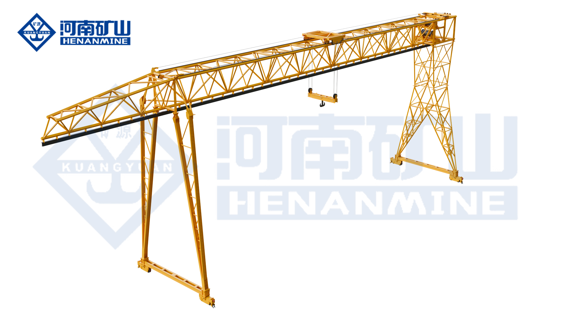
  • Automated Container Gantry Crane Completes Railway Project Load Test

    Automated Container Gantry Crane Completes Railway Project Load Test

    Project Deliveries

    Automated Container Gantry Crane Completes Railway Project Load Test

    Henan Mine Crane completed a factory-stage load test for an automated container gantry crane built for an overseas railway project. The crane is specified for A8 heavy-duty service and container handling at ambient temperatures as low as −40°C.

    Blue automated rail-mounted container gantry crane lifting a shipping container during a factory load test
    The automated container gantry crane lifting a container at the factory test area.

    Heavy-duty handling in a cold climate

    The crane is intended for high-frequency container handling at a railway project. Its A8 duty classification and cold-weather design are relevant where operating cycles and low ambient temperatures require a purpose-designed terminal configuration.

    For a comparable terminal, specify container sizes and gross masses, spreader interface, required stacking height, rail gauge, travel distances, operating cycles, wind and ice exposure, and the temperature range for all electrical and mechanical components.

    Automation and monitoring configuration

    The project package includes variable-frequency drives with energy feedback, an ACCS automation control system and GPS-based positioning. Crane-status visualisation and integration with logistics information form part of the equipment configuration.

    Before procurement, define the required operating modes, positioning tolerances, obstacle and personnel detection, interlocks, remote-operation boundaries, data interfaces, network availability and fallback procedures. Obtain a functional specification and acceptance tests for each included automation feature.

    Set the scope for an overseas railway terminal

    A factory load test is one milestone. Ask for its load cases and records, the general arrangement, component material and cold-weather ratings, electrical schematics, software and interface documents, inspection plan, spare parts, export packing and delivery responsibilities. Clarify who will install, commission and validate the complete system at the destination site.

    Plan an Automated Container Gantry Crane

    Send your container handling plan, duty cycle, rail layout, minimum ambient temperature and automation interfaces for a project-specific proposal.

  • Truss Gantry Crane

    Truss Gantry Crane

    Gantry Cranes / Henan Mine Crane

    Truss Gantry Crane

    Handle yard materials with a truss-structure gantry crane matched to the load and working area. Define lifting coverage, leg geometry and the transport or assembly arrangement for the site.

    Lifting capacity5 – 100 t
    Span18 – 35 m
    Working classSpecified for the project
    Technical specifications

    Define the total suspended load, duty and site conditions for your project.

    Technical specifications

    Check the load.
    Plan the configuration.

    Parameters and equipment options are matched to the application and confirmed in the technical proposal.

    Discuss your configuration
    Lifting Capacity5 – 100 t
    Span18 – 35 m
    Lifting Height6 – 30 m
    Working Temperature Range-20℃ ~ 40℃
    Lifting Speed0.1 – 8 m/min
    Traveling Speed5 – 40 m/min (Long Travel); 3 – 20 m/min (Trolley Travel)
    Control ModeCab control, wireless remote control, or both
    Protection ClassIP54(Electrical Components)
    Motor TypeYE4 ultra-high efficiency energy-saving motor

    Final parameters, dimensions, wheel loads and supply scope follow the approved project specification.

    Application & operation

    Matched to the handling task.

    Storage and loading yards

    Move declared loads between pickup, storage and vehicle positions.

    Construction handling

    Coordinate the crane envelope and runway with the site lifting task.

    Selection considerations

    Start with your operating conditions.

    01

    Load & lifting arrangement

    Specify workpiece dimensions, suspended load and lifting points. Include lifting-appliance weight and the required lifting positions.

    02

    Site & available space

    Provide span, leg clearance, runway layout and assembly access. Coordinate the installation interfaces with the available site drawings.

    03

    Duty & control sequence

    Define lifting cycle, outdoor exposure and control method. Identify the required movements and control interfaces in the enquiry.

    Configuration comparison

    Compare related lifting arrangements.

    Crane arrangementHandling configuration
    Truss Gantry CraneHandle yard materials with a truss-structure gantry crane matched to the load and working area. Define lifting coverage, leg geometry and the transport or assembly arrangement for the site.
    Double Girder Truss Gantry CraneUse a double-girder truss gantry for yard or construction handling with the lifting points specified for the load. Define trolley quantity, coordinated movements and the transport or assembly constraints.
    Double Girder Gantry CraneHandle machinery, steelwork and other heavy loads with a double-girder gantry crane. The lifting mechanism, runway, legs and any cantilevers are selected for the complete yard operation.
    Single-Girder Gantry CraneCover an outdoor working area with a single-girder electric-hoist gantry crane. Coordinate span, lifting height, leg geometry and any cantilever coverage with the yard and loading route.

    Operating protection & lifecycle support

    Plan beyond the equipment.

    01

    Operating protection

    Define travel limits, overload protection, traffic clearances and the outdoor operating limits for the proposed arrangement.

    02

    Installation & commissioning

    Agree rail foundations, runway alignment, wheel-load interfaces, erection access, electrical connections and commissioning responsibilities.

    03

    Inspection & spares

    Plan inspection and maintenance of truss connections, trolley equipment and gantry travel assemblies. Agree service access, documentation and the required spare-parts scope.

    Questions before the order

    Clarify the details
    that shape the crane.

    What information is needed for a truss gantry crane quotation?+

    Provide workpiece dimensions, suspended load and lifting points; span, leg clearance, runway layout and assembly access; and lifting cycle, outdoor exposure and control method. Include drawings and the project destination when available.

    What installation information is needed for a truss gantry?+

    Provide the runway layout, assembly area, lifting access and site constraints. The proposed structure, connections and erection sequence must be coordinated with those conditions.

    What installation and support scope should be agreed?+

    Agree rail foundations, runway alignment, wheel-load interfaces, erection access, electrical connections and commissioning responsibilities. Specify the documentation, training and spare-parts support needed for the project.

    Related equipment

    Explore the alternatives.

    Let’s discuss your project

    The right crane starts
    with your lifting task.

    Share workpiece dimensions, suspended load and lifting points, together with your site layout and operating cycle.

    info@hnksglobal.com
  • Three Trolley Electric Hoist Crane

    Three Trolley Electric Hoist Crane

    Overhead Cranes / Henan Mine Crane

    Three Trolley Electric Hoist Crane

    Coordinate three electric-hoist trolleys for long components or several workshop lifting positions. Define hook loads, trolley spacing and permitted individual or combined movements.

    Lifting capacity1 – 32 t
    Span7.5 – 31.5 m
    Working classA5 – A6
    Technical specifications

    Define the total suspended load, duty and site conditions for your project.

    Technical specifications

    Check the load.
    Plan the configuration.

    Parameters and equipment options are matched to the application and confirmed in the technical proposal.

    Discuss your configuration
    Capacity1 – 32 t
    Span7.5 – 31.5 m
    Lifting height6 – 30 m
    Working classA5 – A6
    Hoisting speed0.8/5 – 8/16 m/min
    Trolley travel5 – 25 m/min
    Crane travel10 – 30 m/min
    Power supply220-690V, 50/60Hz
    ControlsRemote Control + Cabin Control

    Final parameters, dimensions, wheel loads and supply scope follow the approved project specification.

    Application & operation

    Matched to the handling task.

    Long fabricated components

    Coordinate the declared lifting points and workpiece support positions.

    Multiple workstations

    Use the defined trolley functions within the bridge operating area.

    Selection considerations

    Start with your operating conditions.

    01

    Load & lifting arrangement

    Specify load at each hook, lifting points and component centre of gravity. Include lifting-appliance weight and the required lifting positions.

    02

    Site & available space

    Provide trolley spacing, hook coverage and building clearances. Coordinate the installation interfaces with the available site drawings.

    03

    Duty & control sequence

    Define individual or coordinated movements and permissible load combinations. Identify the required movements and control interfaces in the enquiry.

    Configuration comparison

    Compare related lifting arrangements.

    Crane arrangementHandling configuration
    Three Trolley Electric Hoist CraneCoordinate three electric-hoist trolleys for long components or several workshop lifting positions. Define hook loads, trolley spacing and permitted individual or combined movements.
    Double Trolley Electric Hoist CraneLift long components or serve separate working positions with two electric-hoist trolleys on one bridge. Trolley spacing, load sharing and independent or coordinated operation are specified for the task.
    Modular Electric Hoist Overhead CraneUse a modular electric-hoist overhead crane for production, assembly and maintenance lifting. Select the hoist arrangement, hook coverage and movement control for the workshop and operating cycle.
    LH Electric Hoist Double Girder CraneUse an LH double-girder bridge with an electric-hoist trolley for workshop lifting, assembly and maintenance. Match the hoist arrangement to the suspended load, hook travel and available building space.

    Operating protection & lifecycle support

    Plan beyond the equipment.

    01

    Operating protection

    Confirm overload protection, travel limits, brakes, emergency controls and the required process interlocks for the declared lifting task.

    02

    Installation & commissioning

    Agree runway reactions, structural interfaces, electrical connections, assembly, inspection and commissioning responsibilities before delivery.

    03

    Inspection & spares

    Plan inspection and maintenance of hoist ropes, trolley-separation devices and coordinated controls. Agree service access, documentation and the required spare-parts scope.

    Questions before the order

    Clarify the details
    that shape the crane.

    What information is needed for a three trolley electric hoist crane quotation?+

    Provide load at each hook, lifting points and component centre of gravity; trolley spacing, hook coverage and building clearances; and individual or coordinated movements and permissible load combinations. Include drawings and the project destination when available.

    Can all three hoists operate together?+

    State the required operating combinations and load at each hook. The crane structure, controls and lifting plan must define the permissible individual and coordinated operations.

    What installation and support scope should be agreed?+

    Agree runway reactions, structural interfaces, electrical connections, assembly, inspection and commissioning responsibilities before delivery. Specify the documentation, training and spare-parts support needed for the project.

    Related equipment

    Explore the alternatives.

    Let’s discuss your project

    The right crane starts
    with your lifting task.

    Share load at each hook, lifting points and component centre of gravity, together with your site layout and operating cycle.

    info@hnksglobal.com