Engineering · Manufacturing · Project support
info@hnksglobal.comWhatsApp +86 18836207779 ↗

Blog

  • Bulk Handling Cranes: Match the Grab to the Material and Transfer Cycle

    Bulk Handling Cranes: Match the Grab to the Material and Transfer Cycle

    Selection guide

    Bulk Handling Cranes: Match the Grab to the Material and Transfer Cycle

    Bulk handling requires the material, attachment and crane motions to be considered together. Describe density, material condition and transfer points so the proposed grabbing and lifting arrangement can be developed for the operation.
    Henan Mine CraneSelection guide · Updated 2026Crane selection, project scope and operating requirements
    Bulk Handling Cranes
    Bulk Handling Cranes
    Project planning notes

    Key points for this crane project.

    1. What Are Bulk Handling Cranes?
    2. Selection Considerations
    3. Bulk Handling Crane System Comparison
    Read the technical guide

    What Are Bulk Handling Cranes?

    Bulk handling cranes are crane systems equipped with a grab bucket or another process attachment for repeated handling of unpackaged loose material. The search term describes an application family rather than one fixed crane model. The correct system may be an overhead crane above a bunker, a gantry crane over an open stockyard, an automated grab crane serving a production process or a portal crane transferring cargo between vessel and quay.

    The crane, grab and supporting infrastructure operate as one material-handling system. A quotation based only on nominal tonnage can produce insufficient net payload, slow cycle performance, premature wear or an incomplete supply scope. Material, throughput, duty, geometry, control, environment and commercial boundaries must be defined together.

    Production Feeding

    Transfer from storage pits or stockpiles into hoppers, furnaces, crushers, mixers and process lines.

    Stockyard Transfer

    Loading, unloading, sorting and stockpile management across indoor or outdoor storage areas.

    Waste and Recycling

    High-cycle movement, blending and feeding of municipal, industrial or recyclable material.

    Port Cargo Handling

    Ship-to-shore or terminal transfer where outreach, luffing, slewing and grab duty are required.

    Selection Considerations

    Material Characteristics

    Bulk density, particle range, moisture, flowability, compaction, abrasion, corrosion and temperature determine the grab.

    Capacity and Grab Weight

    The specification must state whether capacity means total suspended mass or net material capacity below the grab.

    Throughput and Cycle

    Required tonnes per hour, pick and discharge points, travel distances and operating availability establish performance.

    Pickup and Discharge Layout

    Stockpile, pit, bunker, vessel and hopper geometry determine span, lift, travel, outreach and clearance.

    Overhead, Gantry or Portal

    Coverage, supporting structure, outdoor exposure, floor traffic and vessel interface govern the system type.

    Service and Reliability

    Cycles per hour, operating hours, load spectrum, starts and production criticality establish the required duty.

    Dust, Corrosion and Hazard

    Airborne dust, combustible material, corrosion, humidity, wind, rain and classified areas require formal review.

    Controls and Project Boundary

    Cabin, radio or automation plus rails, power, civil work, freight, erection, testing and training must be defined.

    A complete enquiry includes material data, required throughput, pickup-and-discharge arrangement, capacity basis, span, lifting height, travel length, operating duty, control method, power supply, environment, installation country and supply boundary.

    Bulk Handling Crane System Comparison

    The product ranges below support initial configuration screening. Final capacity, span, lifting height, duty, grab and standards remain project-specific.

    Crane SystemSuitable ApplicationSelection Boundary
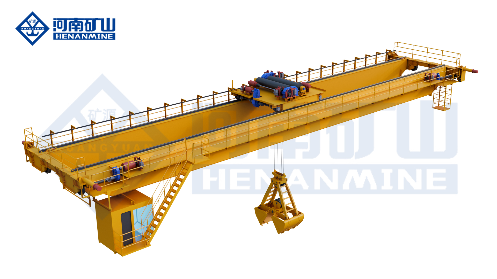
    Single-Girder Grab Overhead CraneIntermittent light- or medium-duty transfer in warehouses and process areasEconomical where throughput and net payload suit the single-girder design
    Intelligent Double-Girder Grab CraneHigh-cycle coal, ore, coke, slag, lime, sand and aggregate handlingDemanding duty, high output, process integration or automated operation
    Grab and Hook Overhead CraneFacilities handling loose material and conventional unit loads in one bayAttachment conversion and capacity definition require coordination
    Grab and Hook Gantry CraneOutdoor yards or buildings without a suitable elevated runwayRails, foundations, wind, power supply and traffic routes govern scope
    Portal Harbor CraneBulk cargo transfer between vessel, quay hopper, truck and terminal storageVessel, quay, outreach, grab duty, wind and marine protection are essential

    Material Data and Grab Bucket Selection

    Four-Rope Mechanical Grab

    A four-rope clamshell grab uses dedicated holding and closing ropes and is commonly selected for repeated high-cycle handling of free-flowing material. Winches, drums, ropes and grab are engineered together.

    Electro-Hydraulic or Motor Grab

    A powered grab supports detachable or mixed-use duties. Attachment power, cable management, maintenance access and achievable cycle performance require inclusion in the crane design.

    Orange-Peel or Special Grab

    Irregular scrap, rock and mixed waste may require an orange-peel or purpose-designed attachment. Tine shape, penetration, closing force and retention are matched to the feed.

    Grab and Hook Combination

    A detachable grab and hook configuration supports mixed bulk and unit-load work. Conversion frequency, connection method and attachment storage form part of the specification.

    Net Material Payload

    Material per cycle = effective grab volume × bulk density × practical fill factor.

    Grab volume alone does not establish output. The loaded grab, ropes and rigging must remain within the stated capacity basis. Contract documents should explicitly distinguish total suspended mass from net material capacity below the grab.

    MaterialPrincipal ConditionsSelection Priorities
    Coal and biomassLow or variable density; dust and combustible-material risks may applyBucket volume, dust control and ignition-hazard assessment
    Ore, coke and slagHigh density, abrasion, impact and possible elevated temperatureGrab strength, wear protection, mechanism duty and temperature suitability
    Sand and aggregatesFlowable but abrasive; moisture changes filling and releaseShell closure, cutting edges, fill factor and hopper opening
    Waste and recyclablesIrregular shapes, variable density, entanglement and uncertain compositionAttachment penetration, retention, fire monitoring and protected controls
    Grain and feedDust, hygiene, contamination and moisture considerationsTight-closing grab, cleanable surfaces and dust-hazard engineering
    Cement and fine powderHigh dust and leakage potential during closing, travel and dischargeEnclosed grab and extraction assessment; conveyor or pneumatic transfer may be preferable

    Throughput, Cycle Time and Duty

    Bulk crane output depends on material retained in each grab cycle and the number of complete cycles achieved under operating conditions. Rated crane capacity is not equivalent to hourly throughput.

    Material per Cycle

    Effective grab volume, bulk density and realistic fill factor establish net material mass. Grab and rigging mass are checked against capacity.

    Complete Cycle Time

    Closing, hoisting, trolley and bridge travel, lowering, opening, return travel and positioning form the complete cycle.

    Operating Availability

    Pile shape, digging resistance, hopper waiting, spillage, control response, inspection and process delays reduce practical output.

    Theoretical hourly throughput = net material per cycle × completed cycles per hour.

    Guaranteed process output requires agreed material properties, operating route, availability assumptions and acceptance-test conditions. Duty classification is selected from load spectrum and cycle demand, not nominal capacity alone.

    Overhead and Gantry Configurations

    Grab Overhead Crane

    An overhead crane provides full-bay coverage without crane legs occupying the floor. It is suitable above storage pits, bunkers and process buildings with an adequate runway structure.

    Single- or Double-Girder Design

    Single-girder construction can suit moderate capacity and intermittent service. Double-girder construction is evaluated for higher duty, larger grabs, wider spans, open-winch machinery and maintenance access.

    Dedicated or Dual-Purpose

    A dedicated grab crane supports repeated process duty. A grab-and-hook crane covers more task types but requires defined conversion procedures and may not match a dedicated high-cycle system.

    Control Method

    Cabin operation supports process supervision; radio control supports selected manual duties; automated operation supports repeatable routes and plant integration.

    Grab Gantry Crane

    A gantry crane transfers reactions through crane legs to rails and foundations. It can cover outdoor stockpiles or buildings without an elevated overhead-crane runway.

    Rails and Foundations

    Wheel loads, rail alignment, foundation stiffness, drainage and settlement criteria affect reliable travel. Vehicle and pedestrian crossings require coordinated protection.

    Outdoor Protection

    Wind limits, storm anchoring, rail clamps, corrosion protection, rain covers, drainage and cable management form part of an outdoor design.

    Portal Cranes for Bulk Cargo Terminals

    Vessel and Quay Interface

    Working radius, vessel hatch position, water-level range, quay elevation and portal clearance establish the operating envelope.

    Luffing, Slewing and Travel

    Coordinated hoisting, luffing, slewing and portal travel determine cargo cycle time. Drives and controls reflect duty, wind and terminal procedures.

    Quay Infrastructure

    Rail gauge, wheel loads, power, storm anchoring, cable routes, access and maintenance zones must suit the quay structure.

    Cargo Route

    Grab discharge may feed a hopper, conveyor, truck or storage system. Dust containment, spillage control and traffic coordination affect the terminal solution.

    Bulk Handling Crane Specification Schedule

    ItemRequired Project DataEngineering Significance
    MaterialName, density, particle size, moisture, temperature, abrasion, corrosion and hazard dataGoverns grab type, volume, materials, wear protection and environment package
    ThroughputRequired t/h, peak demand, operating hours, availability and acceptance basisEstablishes payload, speed, cycle model, crane quantity and duty
    Capacity basisTotal suspended load or net capacity under grab; grab and rigging massPrevents ambiguity in usable material payload and structural load
    GeometrySpan, lift, travel, outreach, pile, pit, bunker, vessel and hopper dimensionsDefines crane arrangement, grab path and cycle distance
    Duty and speedsCycles, load spectrum, starts, hoisting, trolley and crane travel requirementsAligns structures, motors, brakes and controls with service demand
    ControlCabin, radio, automation, position data, anti-sway and plant interfacesDefines sensors, PLC architecture and operating functions
    Power and environmentVoltage, frequency, temperature, dust, wind, rain, humidity and classified zonesSets electrical design, enclosures, coating and special protection
    Project boundaryCrane, grab, rails, runway, power, civil work, freight, erection, testing, training and sparesEnables technically and commercially comparable quotations

    Controls, Automation and Environmental Protection

    Motion and Position

    Variable-frequency drives, position feedback and anti-sway functions can support controlled cycles and accurate discharge.

    Automatic Routes

    Defined pick, transfer and discharge paths can include pile scanning, restricted zones and hopper selection.

    Dust and Wear

    Controlled discharge, protected enclosures, suitable coating and replaceable grab wear parts reflect the material and atmosphere.

    Hazardous Areas

    Zone classification, ignition data, equipment category, surface temperature, earthing and all ignition sources require formal review.

    Automatic-cycle boundaries, sensor inputs, interlocks, recovery modes, manual override, data interfaces, output assumptions and site-acceptance conditions should be defined before contract award. A single protected component does not make the complete crane suitable for a hazardous area.

    Bulk Handling Crane Project Case

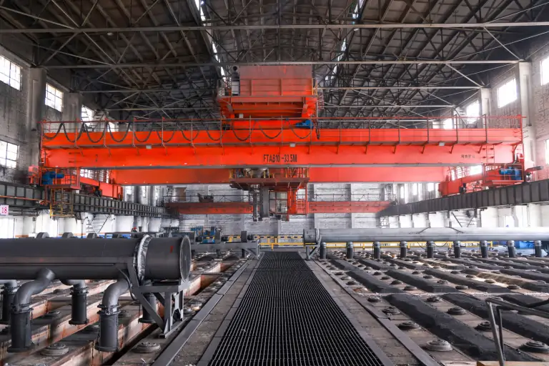
    Unmanned Grab Bucket Overhead Crane for Baowu Group Shaoguan Steel Plant

    The project serves a bulk-material process associated with rotary-hearth-furnace steelmaking. Crane configuration and automatic control were developed for repeated material pickup, transfer and discharge within the designated production area.

    Process Requirement

    Repeatable material movement, defined operating zones and coordinated discharge into the production process.

    Engineering Focus

    Grab logic, crane positioning, automatic routes, operational interlocks and plant-system coordination.

    Procurement Relevance

    The installation demonstrates why crane machinery, grab, automation and process interfaces must be treated as one system.

    Engineering, Manufacturing and Documentation

    Application Review

    Material, output, cycle, capacity, geometry, duty, wheel loads, controls and site interfaces are reviewed before design.

    Controlled Production

    Fabrication, machining, assembly, coating and component installation follow approved drawings and agreed processes.

    Inspection and Testing

    Dimensions, welds, mechanisms, electrics, protection devices and factory functions are checked under the contract plan.

    Project Document Package

    Approved drawings, data sheets, electrical diagrams, manuals, certificates, inspection records and test documents are supplied as specified.

    Installation, Commissioning and Maintenance

    Pre-Installation Verification

    Runway or rail geometry, foundations, clearances, power, access, lifting plan, storage area and responsibilities are confirmed before erection.

    Commissioning and Acceptance

    Alignment, electrical checks, limits, brakes, protective functions, load tests, grab operation and process interfaces follow the agreed plan.

    Duty-Based Maintenance

    Ropes, drums, sheaves, brakes, wheels, rails, grab pins, bushes, shells, cutting edges, hydraulics and electrics require documented inspection.

    Lifecycle Planning

    Commissioning and operating spares should reflect crane criticality and local availability. Grab and rope-system wear parts deserve particular attention in abrasive or continuous-duty service.

    Bulk Handling Crane Price

    Bulk handling crane price varies substantially because capacity, grab system, duty, span, lift, cycle performance, automation and supply boundary differ between projects. Equipment-only figures cannot be compared directly with installed systems including runway or rails, power, civil work, freight, erection and commissioning.

    Automated grab cranes and portal harbor cranes require engineered project quotations. These figures are not Henan Mine Crane quotations.

    Crane Equipment

    Structure, trolley, drives, ropes, drums, brakes, wheels, electrics, controls and safety functions.

    Grab and Process

    Grab type, volume, wear materials, attachment power, automation, sensors and process interfaces.

    Infrastructure

    Runways, columns, rails, foundations, power, cable routes, dust control and access platforms.

    Delivery and Site Work

    Packing, freight, import charges, erection, commissioning, tests, training and spares.

    Information Required for an Accurate Price

    Material and density · particle size and moisture · required t/h · pickup and discharge geometry · capacity basis · grab type · span and lift · travel or outreach · duty and cycles · control and automation · dust, corrosion and hazard conditions · power · rails and civil scope · installation country · delivery terms · erection, testing, training and documentation.

    Bulk Handling Crane FAQ

    What materials can a bulk handling crane move?

    Typical applications include coal, ore, coke, slag, lime, sand, aggregates, biomass, waste and selected grain products. Material data determine suitability.

    Which grab is suitable for bulk material?

    Free-flowing material commonly uses a clamshell grab. Irregular scrap or waste may require an orange-peel or special-purpose grab. Geometry, force, wear and power arrangements are material-specific.

    Does crane capacity include the grab?

    Capacity terminology must be stated in the contract. It may describe total suspended mass including the grab or net material capacity below the grab.

    How is throughput calculated?

    Net material per cycle comes from effective grab volume, density and fill factor. Hourly output then depends on the complete operating cycle and availability.

    When is a gantry crane preferable?

    A gantry crane is commonly evaluated for outdoor yards or sites without an elevated runway. Coverage, foundations, traffic and environmental exposure govern the choice.

    Can bulk handling cranes operate automatically?

    Automation can include position feedback, pile scanning, anti-sway, defined routes, hopper selection, restricted zones and plant-control communication.

    Can a grab crane handle combustible dust?

    Suitability depends on formal hazard classification. The complete crane, grab, electrical system, mechanical ignition risks, earthing and dust controls must comply.

    Is a grab crane suitable for fine powder?

    An enclosed grab and extraction can be evaluated, but conveyor, screw or pneumatic transfer may be more suitable where containment and continuous flow govern.

    How much does a bulk handling crane cost?

    Price depends on capacity, grab, duty, output, span, automation, infrastructure, protection, freight and site services. Supply boundaries must be normalized before comparison.

    What is required for a quotation?

    Material, throughput, layout, capacity basis, span, lift, travel, duty, controls, environment, power, infrastructure, country and required project scope are required.

    Related Bulk Handling Crane Systems

    Single-Girder Grab Crane

    Economical overhead configuration for intermittent light- and medium-duty bulk transfer.

    Intelligent Double-Girder Grab Crane

    High-duty system for demanding cycles, automation and process integration.

    Grab and Hook Overhead Crane

    Dual-purpose system for bulk material and conventional hook loads.

    Grab and Hook Gantry Crane

    Ground-supported solution for stockyards and sites without an overhead runway.

    Portal Harbor Crane

    Luffing and slewing terminal crane for vessel-to-quay bulk cargo transfer.

    Submit material properties, required throughput, pickup and discharge layout, capacity basis, span, lifting height, duty, controls, environment, power, installation location and project scope. Henan Mine Crane will prepare a crane configuration and commercial quotation from verified application data.

    Discuss the crane arrangement for your project.

    Bulk handling requires the material, attachment and crane motions to be considered together. Describe density, material condition and transfer points so the proposed grabbing and lifting arrangement can be developed for the operation. Share the load, available drawings, working cycle and site conditions with Henan Mine Crane so the required configuration and supply boundary can be discussed.

    Related crane configurations

    Grab And Hook Dual Purpose Crane

    View product parameters
    Lifting capacity: 5 – 16 tSpan: 10.5 – 31.5 mLifting height: 6 – 20 m

    Switch between bulk-material pickup and hook lifting with a grab-and-hook overhead arrangement. Define each load case, the grab type and the changeover procedure for the working area.

    Grab Hook Gantry Crane

    View product parameters
    Lifting capacity: 1t – 20tSpan: 6m – 30mLifting height: 4m – 18m

    Combine grab and hook handling on an electric-hoist gantry arrangement. Match the lifting appliance, load cases and changeover method to the outdoor handling layout.

    Updated 2026 · Henan Mine Crane
  • Bridge Crane Systems: Understand Coverage, Hoists and Runway Interfaces

    Bridge Crane Systems: Understand Coverage, Hoists and Runway Interfaces

    Selection guide

    Bridge Crane Systems: Understand Coverage, Hoists and Runway Interfaces

    A bridge crane needs to move the load between the required working positions within the building. Define the handling task and runway information before comparing structural and lifting-mechanism arrangements.

    Henan Mine CraneSelection guide · Updated 2026Crane selection, project scope and operating requirements
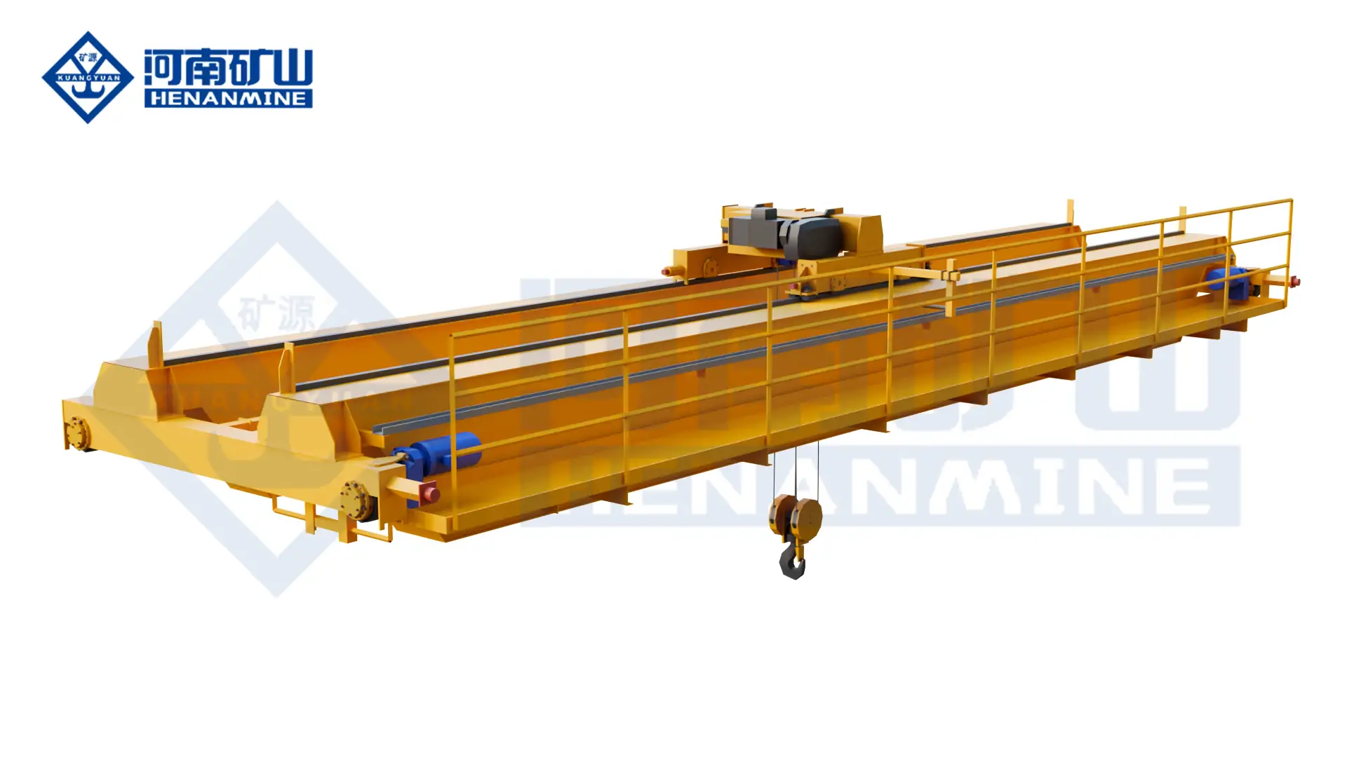
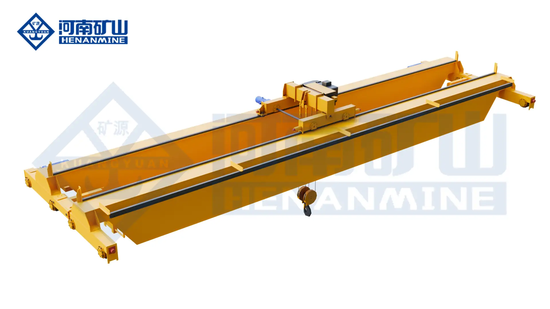
    Henan Mine Crane LH Electric Hoist Double Girder Crane
    Henan Mine Crane LH Electric Hoist Double Girder Crane
    Project planning notes

    Key points for this crane project.

    1. Bridge Crane Design and Applications
    2. Bridge Crane Technical Specifications
    3. Selection Considerations
    Read the technical guide

    Bridge Crane Design and Applications

    A bridge crane carries a hoist or trolley across a bridge spanning the working bay. The bridge travels along elevated runways, while the hoist raises and lowers the load. Together, these movements serve material pickup, transfer and placement points within the available hook coverage.

    In industrial enquiries, bridge crane and overhead crane usually describe this same moving-bridge arrangement. An electrically powered travelling design is also called an EOT crane. Its suitability depends on the layout and handling task, rather than which name appears in the enquiry.

    Workshop and Assembly

    Transfer components between machining, fabrication and assembly stations. Define the load orientation and positioning needs at each station.

    Warehouse and Maintenance

    Serve storage lanes and equipment repair areas within the crane bay. Check hook access around racks, machines, doors and overhead services.

    Process Material Handling

    Match the lifting attachment and operating duty to bulk materials, steel products or specialised production tasks.

    Bridge Crane Technical Specifications

    A bridge crane is a configurable system. The technical proposal should identify the selected values and interfaces below; one general parameter range cannot describe every single-girder, underhung and process crane.

    ParameterProject Specification
    Rated lifting capacitySpecified for the maximum lifted load and the agreed treatment of slings, lifting beams, grabs or other attachments.
    Crane spanSet from the runway centreline spacing. Provide support positions for an underhung or multi-support system.
    Lifting height and hook levelsState the highest and lowest required hook positions, including any pit or below-floor lift.
    Runway length and hook coverageDefine longitudinal travel and hook approaches at the sides and ends of the bay.
    Bridge and hoist arrangementSingle or double girder; electric hoist or winch trolley; top-running or underhung bridge as applicable.
    Crane and mechanism dutySelected from load spectrum, operating cycles and service requirements under the agreed design standard.
    Hoisting and travel speedsMatched to handling time, load behaviour and placement accuracy. Speed control is specified for each motion.
    Control methodPendant, radio remote, cabin or project-specific automation, with a defined control priority.

    A higher capacity or a different duty cycle should be assessed with the same building and load information.

    Selection Considerations

    Load and Handling Route

    List the heaviest load, typical load, dimensions, centre of gravity and lifting attachment. Mark pickup and placement points so the hook can reach each position without obstruction.

    Building and Runway

    Provide a plan and cross-section showing runway levels, roof steelwork, columns and services. Existing supports require a structural assessment using the proposed crane reactions.

    Production Cycle

    Describe lifts per hour, travel distances, operating shifts and the proportion of lifts near rated load. These inputs affect mechanism selection and duty classification.

    Environment and Access

    Identify heat, dust, moisture, corrosion or explosive atmospheres. Reserve access for inspection, lubrication and removal of components during maintenance.

    Single-girder and double-girder describe the bridge beams. Top-running and underhung describe how the bridge travels on its runways. A hoist suspended below a single girder does not, by itself, make the whole crane an underhung crane.

    Bridge Crane Compared with Other Industrial Crane Configurations

    Compare the complete arrangement at the required load and hook position. Structural weight, available headroom and support costs depend on the proposed design; neither girder count nor rated capacity alone determines the lowest installed cost.

    ConfigurationStructural ArrangementApplication FitSelection Trade-Off
    Single-Girder Bridge CraneOne bridge girder, commonly with an electric hoist travelling below it.General workshop, warehouse and maintenance handling.Compare hook height, side approaches, hoist duty and runway loading for the actual layout.
    Double-Girder Bridge CraneTwo bridge girders supporting the selected trolley and lifting mechanism.Projects needing a different trolley layout, lifting envelope or equipment arrangement.A double girder does not automatically mean heavy duty; confirm the rated duty and complete crane dimensions.
    Underhung Bridge CraneBridge end carriages travel on the lower flanges of suitable runway beams.Layouts where a suspended runway arrangement suits the building.Assess runway beam flanges, connections, support capacity and clearance. Roof suitability is project-specific.
    Multi-Support Underhung CraneAn underhung bridge arranged across multiple runway supports.Large assembly areas and facilities with an engineered multi-rail layout.Coordinate support spacing, alignment and load distribution across the supporting structure.
    Gantry CraneA bridge supported by travelling legs, with the runway typically at ground level.Yards or buildings where an elevated runway is unsuitable.Allow for legs, ground rails or travel lanes, foundations and operating clearances.

    Hoist, Trolley and Bridge Movement

    Hoisting: Vertical Movement

    The lifting mechanism raises and lowers the suspended load. Select rope travel, hook arrangement, braking and speed control around the lift and placement requirements.

    Trolley Travel: Across the Bay

    The trolley or travelling hoist moves along the bridge. Trolley dimensions and end clearances affect how closely the hook can approach either side.

    Bridge Travel: Along the Bay

    End carriages move the bridge along the runways. Wheel arrangement, drive selection and runway alignment must work together over the travel length.

    For restricted headroom, compare the proposed highest hook level and crane envelope on the building cross-section. A low-headroom hoist or a different bridge arrangement may help, but the result must include roof clearance, services and maintenance access.

    Load Handling and Special Environments

    The lifting attachment and process can change the crane specification as much as the load capacity. Discuss these configurations when a general hook crane does not cover the work:

    • Double-trolley handling: for long components or work requiring two lifting points. Define individual hoist ratings, shared-load limits, hook spacing and the intended coordinated movements.
    • Grab bridge cranes: for bulk materials. Provide bulk density, material condition, discharge height and required throughput so grab capacity and duty can be evaluated together.
    • Electromagnetic bridge cranes: for suitable steel products. Identify material shape, surface condition and temperature, and define the required response to a loss of lifting power.
    • Metallurgical bridge cranes: for specified hot-material or production duties. Describe the process, radiant heat and consequences of interrupted lifting; molten-metal handling requires a dedicated design review.
    • Explosion-proof bridge cranes: for a defined hazardous area. Supply the site classification and gas or dust information so equipment protection and required documentation can be assessed.

    Safety, Controls and Redundancy

    The safety and control schedule should be part of the quotation. Required protections and optional functions must be clearly identified for the chosen crane and site.

    Load and Motion Protection

    Specify overload protection, hoisting and travel limits, braking arrangements, emergency stops and relevant electrical protections. Confirm how each function will be demonstrated at acceptance.

    Operator Control

    Choose pendant, radio remote or cabin operation around visibility and operator access. For multiple control stations, define selection priority and the response to a lost command signal.

    Shared Runways and Automation

    Where cranes share a bay, assess collision prevention and operating separation. Anti-sway, positioning and process interfaces require a defined performance target and acceptance method.

    Dual hoists, additional brakes, monitoring and standby functions are engineered for the intended duty. Their availability and scope should be confirmed in the technical proposal rather than assumed from the crane name.

    Installation, Acceptance and Maintenance

    Installation Interfaces

    Agree who supplies the crane, runway beams, rails, conductors, supporting steelwork and foundations. Provide unloading access, assembly space and the planned installation window.

    Acceptance and Documentation

    Agree drawing approvals, inspection records, electrical diagrams, manuals and the factory and site test scope before ordering. Define the responsibilities for site commissioning and operator familiarisation.

    Maintenance Access

    Plan access to the hoist, trolley, wheels, drives and power supply. Identify replacement clearances and the spare parts needed for the operating schedule.

    For a replacement bridge crane, survey the existing runway and electrical supply. The previous crane’s rated capacity alone does not establish compatibility: the new crane may have different wheel loads, wheel spacing, dimensions or power demand.

    What Determines Bridge Crane Price?

    Bridge crane price depends on rated capacity, span, lifting height, duty, hoist arrangement and operating environment. Runway equipment, installation work, controls, testing and delivery scope can also change the total project cost.

    When comparing bridge cranes for sale, request quotations against the same specification. Ask each supplier to identify the crane supply, runway and power supply scope, selected components, drawings, inspections, delivery terms and installation responsibilities.

    Equipment

    Bridge, end carriages, hoist or trolley and controls.

    Bridge Crane FAQ

    Is a bridge crane the same as an overhead crane?

    In normal industrial usage, the terms often refer to the same crane with a moving bridge on elevated runways. EOT describes an electrically powered overhead travelling crane. Confirm the structure and operating requirements in the specification.

    Should I choose a single-girder or double-girder bridge crane?

    Compare the proposed hook coverage, headroom, runway reactions, duty and total installed scope. Both arrangements can serve industrial handling, and the right choice depends on the specific layout and work cycle.

    Does an underhung crane require a suitable roof structure?

    An underhung crane requires suitable runway beams and supports, which may connect to a building structure or a separate engineered support system. The supporting structure and connections must be assessed for the crane loads.

    Can a bridge crane be fitted to my existing runway?

    Provide the runway drawings and survey information, existing crane data, rail or beam details and power supply. Compatibility must be checked against the new crane’s dimensions, wheel arrangement and reactions.

    Can two hoists lift one load together?

    A coordinated lifting arrangement can be engineered for that duty. Individual hoist capacities do not by themselves establish the permissible combined load. Define load sharing, lifting points, motion control and fault response in the proposal.

    Can the same bridge crane work outdoors or in a hazardous area?

    These conditions need a suitable design. Outdoor projects require assessment of exposure and wind-related requirements; hazardous areas require equipment matched to the site classification. State the environment at the enquiry stage.

    What information is needed for a bridge crane quotation?

    Send the maximum and typical loads, attachment details, span, lifting height, runway length, building drawing, work cycle, power supply and project location. Include any inspection, documentation or installation requirements.

    Send Henan Mine Crane your lifting requirement and building layout for a project-specific bridge crane proposal. Include the following details to help define the configuration and scope:

    • Maximum load, typical load and lifting attachment
    • Span, required hook levels and runway length
    • Operating cycle, site environment and electrical supply
    • Project country, drawings, delivery needs and installation scope

    Discuss the crane arrangement for your project.

    A bridge crane needs to move the load between the required working positions within the building. Define the handling task and runway information before comparing structural and lifting-mechanism arrangements. Share the load, available drawings, working cycle and site conditions with Henan Mine Crane so the required configuration and supply boundary can be discussed.

    Related crane configurations

    LH Electric Hoist Double Girder Crane

    View product parameters
    Lifting capacity: 3, 5, 10, 16, 20 tSpan: 10.5–31.5 mLifting height: 6, 9, 12 or 18 m

    Use an LH double-girder bridge with an electric-hoist trolley for workshop lifting, assembly and maintenance. Match the hoist arrangement to the suspended load, hook travel and available building space.

    Double Trolley Electric Hoist Crane

    View product parameters
    Lifting capacity: 1+1 – 32+32 tSpan: 7.5 – 31.5 mLifting height: 6 – 30 m

    Lift long components or serve separate working positions with two electric-hoist trolleys on one bridge. Trolley spacing, load sharing and independent or coordinated operation are specified for the task.

    Updated 2026 · Henan Mine Crane
  • Bridge Crane Purchasing: Define the Equipment Before Comparing Offers

    Bridge Crane Purchasing: Define the Equipment Before Comparing Offers

    Selection guide

    Bridge Crane Purchasing: Define the Equipment Before Comparing Offers

    A clear purchasing brief helps suppliers respond to the same requirement. State the load, bay geometry and working cycle, then compare the proposed crane and the site responsibilities included in each offer.

    Henan Mine CraneSelection guide · Updated 2026Crane selection, project scope and operating requirements
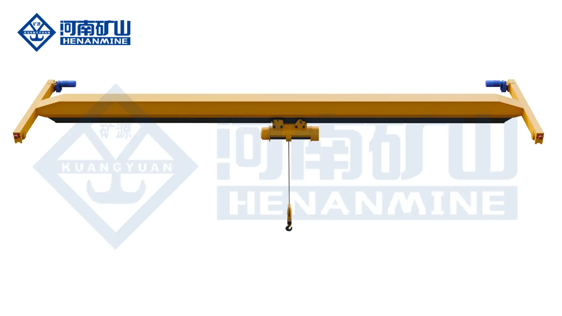
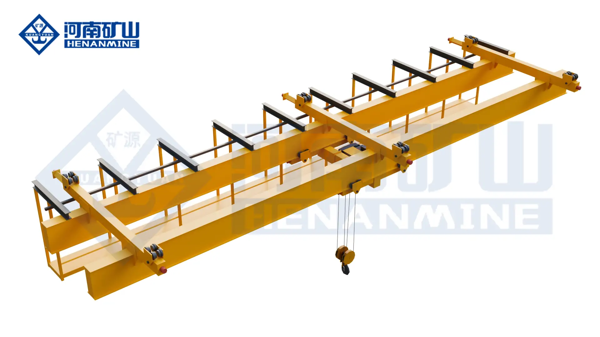
    Henan Mine Crane Single-Girder Bridge Crane
    Henan Mine Crane Single-Girder Bridge Crane
    Project planning notes

    Key points for this crane project.

    1. New Bridge Cranes for Industrial Facilities
    2. Bridge Crane Applications
    3. Bridge Crane Specifications
    Read the technical guide

    New Bridge Cranes for Industrial Facilities

    A bridge crane provides three-axis material movement within a defined bay. The bridge travels along parallel runways, the hoist or trolley moves across the bridge, and the lifting mechanism raises or lowers the load. This arrangement keeps the operating floor clear while providing controlled lifting coverage over production and storage areas.

    Bridge crane, overhead crane and EOT crane are common commercial terms for this equipment family. The purchase specification must identify the actual bridge structure, runway arrangement, hoisting mechanism, duty and control system rather than relying on the product name alone.

    Supply position: The offered range covers newly manufactured, project-configured bridge cranes. Used equipment, rental cranes and generic component kits are outside the standard product scope.

    Bridge Crane Applications

    Manufacturing and Assembly

    Machinery components, fabrications, tooling, molds and assemblies moving between production stations.

    Warehousing and Maintenance

    Inbound materials, stored equipment, maintenance assemblies and controlled loading operations.

    Steel and Metallurgy

    Coils, plates, billets, ladles, scrap, process equipment and high-temperature production materials.

    Power and Process Industry

    Generators, turbines, pumps, production equipment and planned maintenance loads.

    Bulk Material Handling

    Grab-crane systems for coal, ore, aggregate, biomass, waste and process feedstock.

    Hazardous and Special Areas

    Classified, corrosive, dusty, high-temperature or cleanliness-controlled operating environments.

    Bridge Crane Specifications

    The final crane schedule is developed from the operating requirement and building interface. Approved values are stated in the technical proposal and general arrangement drawing.

    SpecificationAvailable Engineering DirectionRequired Project Information
    Rated CapacityConfigured for the selected crane model and serviceMaximum suspended load, attachment weight and load spectrum
    Span and Runway LengthMatched to the working bay and runway geometryRunway gauge, travel distance, support spacing and rail data
    Lifting HeightProject-defined hook travel and approach dimensionsLowest pickup, highest placement, rigging height and building clearances
    Working ClassSelected from operating time, cycles and load spectrumLifts per hour, shifts, loaded cycles, travel distance and process criticality
    Hoisting MechanismWire-rope electric hoist, winch trolley or special mechanismCapacity, duty, lift, speed, headroom, redundancy and access
    Control MethodPendant, radio remote, cabin, remote station or automated controlVisibility, travel distance, staffing, speed control and process interfaces
    Power SupplyElectrical equipment matched to the destination supplyVoltage, frequency, phases, earthing and site distribution
    Operating EnvironmentGeneral, outdoor, hazardous, corrosive, dusty or high-temperature configurationTemperature, humidity, contaminants, hazard classification and local requirements

    Selection Considerations

    Maximum Load and Attachment

    Rated capacity includes the lifted item and below-the-hook equipment. Load geometry and centre of gravity affect the handling arrangement.

    Working Area and Hook Envelope

    Span, runway length, hook approaches, lift and obstructions determine usable coverage inside the crane bay.

    Load Spectrum and Operating Cycle

    Working class and mechanism ratings are aligned with operating hours, starts, travel and the proportion of heavy lifts.

    Runway and Structural Capacity

    Wheel loads, lateral forces, rail size, support spacing and allowable clearances must be coordinated with the supporting structure.

    Control and Motion Performance

    Control position, speeds, variable-frequency drives, anti-sway and positioning functions are selected for the handling process.

    Delivery and Site Responsibility

    Runway, power distribution, freight, erection, commissioning, testing and documentation require defined responsibility.

    Bridge Crane Compared with Other Industrial Crane Configurations

    Equipment selection is based on building support, required lifting coverage, operating duty and load-handling method. The same rated capacity can require a different configuration when the site or production process changes.

    ConfigurationStructural ArrangementApplication PositionCritical Selection Inputs
    Single-Girder Bridge CraneOne bridge girder with an under-running hoistGeneral workshop, warehouse, assembly and maintenance liftingCapacity, span, headroom, duty and runway reactions
    Double-Girder Bridge CraneTwo bridge girders with a selected hoist or trolleyHeavier loads, demanding duty, wider spans and process serviceLoad spectrum, trolley arrangement, hook envelope and access
    Underhung Bridge CraneBridge travels beneath compatible suspended runwaysFacilities where elevated top-running runway columns are unsuitableRoof structure, runway flange, support spacing and clearances
    Double-Trolley Bridge CraneTwo lifting mechanisms operating on one bridgeLong loads, two-point handling and defined coordinated operationsIndividual capacities, combined load, hook spacing and control logic
    Gantry CraneLeg-supported bridge travelling on ground-level rails or wheelsOutdoor yards or facilities without suitable elevated runway supportGround conditions, foundations, travel lanes, wind and cantilevers

    Bridge Crane Configurations

    The commercial description “bridge crane for sale” covers several structural and mechanical arrangements. Configuration selection affects hook coverage, building loads, maintenance access, operating performance and total project scope.

    Single-Girder Bridge Crane

    A single bridge girder carries an electric wire-rope hoist operating beneath the girder. This arrangement is widely specified for general manufacturing, warehousing, maintenance and assembly service.

    • Compact bridge structure for general industrial lifting
    • Electric-hoist mechanism with pendant or radio control
    • Selection governed by span, headroom, duty and runway capacity

    Double-Girder Bridge Crane

    Two bridge girders support an electric hoist or winch trolley. The layout permits alternative hook approaches, service platforms and mechanism arrangements for demanding production service.

    • Suitable for higher loads, wider spans or intensive duty
    • Access platforms and process equipment available by specification

    Underhung Bridge Crane

    The bridge end trucks travel beneath suspended runway beams. This structure can provide lifting coverage where floor-supported runway columns are restricted or where the building has a compatible supporting system.

    • Suspended runway arrangement for defined building conditions
    • Roof and runway support require structural confirmation
    • End approaches and suspension points established by layout

    Special-Purpose Bridge Crane

    Hazardous, metallurgical, high-temperature, corrosive and bulk-handling applications require equipment developed for the stated operating conditions rather than a general-purpose crane with isolated component changes.

    • Hazard classification and material properties defined at enquiry stage
    • Special mechanisms, protection, controls and lifting attachments
    • Technical scope aligned with project acceptance requirements

    Crane, Runway and Building Integration

    A bridge crane is part of an integrated load path. Crane wheel reactions pass through the rails and runway beams into building columns, freestanding supports or another approved structure. The complete arrangement must accommodate vertical loads, transverse forces, longitudinal forces, operating clearances and maintenance access.

    New-Build Facility

    Early coordination permits the crane envelope, runway elevation, support spacing, electrical feed and maintenance access to be incorporated into the building design.

    Existing Runway

    An existing runway requires dimensional and structural assessment. Rail condition, alignment, span, support spacing and permissible reactions are evaluated against the proposed crane.

    Freestanding Runway

    Independent runway columns can separate crane reactions from the main building where space, foundations and operating routes permit a freestanding support structure.

    Interface control: Crane span, rail level, runway gauge, wheel loads, end approaches and power-feed location are recorded in approved project drawings. Building and runway suitability remain subject to competent structural verification.

    Hoisting, Travel and Control Systems

    Hoisting Mechanism

    Wire-rope electric hoists provide a compact mechanism for many general-purpose single- and double-girder cranes. Winch trolleys permit alternative reeving, machinery layouts, access provisions and redundancy for demanding service. The selected mechanism is matched to capacity, lift, speed, duty, headroom and maintenance strategy.

    Bridge and Trolley Travel

    Motor, brake, wheel and drive arrangements are developed for the travel distance, acceleration, operating frequency and required positioning performance. Variable-frequency control can provide smoother acceleration and deceleration where the process requires controlled motion.

    Control Options

    • Pendant control: local control for conventional workshop service.
    • Radio remote control: flexible operating position with the specified control functions.
    • Operator cabin: elevated control position for process cranes, long travel routes or defined visibility requirements.
    • Remote station: control from a fixed operating room or protected station.
    • Automated operation: positioning, interlocks and process communication developed from a defined functional specification.

    Safety and Environmental Configuration

    Protective functions are selected for the crane duty, motion hazards, load characteristics, access conditions and applicable project requirements. The final safety schedule forms part of the technical agreement.

    Load and Hoist Protection

    Upper and lower travel limits, overload protection, braking and other mechanism safeguards are specified for the lifting arrangement.

    Travel Protection

    Travel limits, end stops, buffers, audible or visual warnings and anti-collision functions are applied for the operating layout.

    Electrical Protection

    Isolation, emergency stopping, short-circuit, phase and motor protection are coordinated with the electrical design and site supply.

    Access and Maintenance

    Platforms, walkways, guards, access points and maintenance clearances are defined where required by the crane arrangement.

    Hazardous Areas

    Gas or dust classification, temperature class, zone information and material properties are required before an explosion-protected configuration can be established.

    Outdoor or Corrosive Service

    Weather exposure, wind, ambient temperature, humidity, chemicals and coating requirements determine environmental protection measures.

    Bridge Crane Supply Scope

    A commercially complete comparison requires a defined boundary between crane equipment, runway infrastructure, site services and installation activities. Henan Mine Crane prepares the proposal against the agreed project scope.

    Scope GroupTypical ContentCommercial Definition
    Crane EquipmentBridge structure, end carriages, hoist or trolley, travel drives, electrical equipment and controlsIncluded equipment and technical limits stated in the proposal
    Power and ElectrificationCrane power feed, conductor system, festoon system, isolators and interface cabling as specifiedSupply termination points and site connections identified
    Runway SystemRails, runway beams, columns, brackets, buffers and associated structural items when includedEquipment-only, runway-inclusive or interface-data-only basis stated
    Transport and Site ServicesPacking, freight, unloading, erection supervision, installation, commissioning and testingCommercial terms, destination and responsibility matrix agreed
    Project DocumentationDrawings, technical schedules, electrical information, manuals and agreed inspection recordsDocument language, format, approval stages and submission schedule stated

    Bridge Crane Price Factors

    Bridge crane pricing is project-specific because capacity alone does not define the structure, mechanism, duty or installed scope. A quotation becomes commercially comparable only when all suppliers receive the same technical and delivery requirements.

    Capacity, Span and Lift

    Structural size, hoisting equipment, rope capacity and building interface change with the lifting geometry.

    Duty and Motion Control

    Operating cycle, speeds, variable-frequency drives, positioning functions and redundancy affect equipment selection.

    Environment and Compliance

    Hazard protection, temperature, corrosion, outdoor exposure and project documentation add specific engineering requirements.

    Runway and Site Scope

    Runway steelwork, freight, unloading, installation, commissioning and site testing can materially change total project cost.

    A structured breakdown of equipment and installed-system cost drivers is available under Overhead Crane Pricing.

    Manufacturing, Inspection and Documentation

    Henan Mine Crane develops the manufacturing package from the approved technical agreement and general arrangement. Production and inspection requirements are connected to the selected crane structure, mechanisms, electrical system and contracted documentation scope.

    • Approved general arrangement and interface dimensions before production release
    • Material, fabrication and component controls defined by the manufacturing plan
    • Electrical and mechanism checks performed against the agreed configuration
    • Inspection points, test activities and records aligned with the contract
    • Packing and shipment planning coordinated with crane dimensions and destination

    Manufacturing facilities and production scenes are presented in the Henan Mine Crane factory display.

    Delivery, Installation and Commissioning

    Engineering Approval

    Project drawings, interfaces, components and commercial scope are approved before manufacturing release.

    Production and Inspection

    Manufacturing, assembly checks and agreed inspection activities follow the approved project package.

    Packing and Delivery

    Shipment preparation reflects component protection, lifting points, package dimensions and the contracted delivery term.

    Site Installation

    Runway readiness, lifting access, electrical services and installation responsibilities are confirmed before site work.

    Commissioning and Handover

    Functional checks, agreed testing, records and operating documentation support formal project handover.

    Production and delivery timing depends on configuration, drawing approval, material and component availability, inspection scope, transport arrangement and site readiness. Contract milestones are established for the individual order.

    Information Required for a Bridge Crane Quotation

    A complete enquiry enables technical evaluation, layout development and a defined commercial scope. Building drawings, runway data and load information can be attached where available.

    Environment and Supply

    • Project location, delivery term and required services

    Bridge Crane for Sale FAQ

    What information is needed to price a bridge crane?

    Essential inputs include rated load, span, lifting height, runway length, operating duty, environment, power supply, control method, project location and required supply scope. Drawings and existing-runway data improve dimensional and structural coordination.

    Is a bridge crane the same as an overhead crane or EOT crane?

    These terms commonly describe the same family of travelling-bridge lifting equipment. The technical specification must still define the girder arrangement, runway type, lifting mechanism, duty and control system.

    When is a double-girder crane selected instead of a single-girder crane?

    A double-girder arrangement is evaluated when load, span, working duty, lifting envelope, trolley layout, maintenance access or process requirements exceed the preferred operating range of a single-girder arrangement. Selection is based on the complete project rather than capacity alone.

    Can a new bridge crane operate on an existing runway?

    Compatibility is determined from the existing rail and runway geometry, alignment, support condition and allowable reactions. The proposed crane wheel loads, wheel spacing, power demand and clearances must be assessed against the existing structure.

    Does the quoted bridge crane price include runway beams and installation?

    Inclusion depends on the stated commercial scope. Crane equipment, rails, runway steelwork, power feed, freight, erection, commissioning and testing should be identified separately when comparing proposals.

    Can bridge cranes be configured for hazardous or high-temperature areas?

    Special configurations are available when the hazard classification, temperature, material, exposure and project requirements are defined. General-purpose equipment is not substituted for a purpose-designed crane in these environments.

    Which controls are available for a bridge crane?

    Pendant, radio remote, operator cabin, fixed-station and automated controls can be evaluated. Visibility, operating route, production interface, motion precision and site rules determine the appropriate arrangement.

    How is delivery time established?

    The delivery schedule is established after configuration and scope confirmation. Drawing approval, production complexity, component availability, inspection activities, packing, transport route and site readiness affect the contracted milestones.

    Related Overhead Crane Products

    Single-Girder Overhead Crane

    Electric-hoist bridge crane for general production, warehousing and maintenance service.

    Double-Girder Overhead Crane

    Two-girder structure for demanding duty, alternative trolley layouts and defined lifting envelopes.

    Multi-Support Underhung Crane

    Suspended multi-support arrangement for compatible building and runway conditions.

    Double-Trolley Overhead Crane

    Two lifting mechanisms for defined two-point handling and long-load operations.

    Explosion-Proof Overhead Crane

    Purpose-configured lifting equipment for specified hazardous operating areas.

    5 Ton Overhead Crane

    Five-ton bridge crane configurations for industrial facilities and defined operating duties.

    Submit the required capacity, span, lifting height, duty, building information, power supply, operating environment and project location. Henan Mine Crane will develop a bridge crane proposal with the applicable configuration, technical data and defined supply scope.

    Discuss the crane arrangement for your project.

    A clear purchasing brief helps suppliers respond to the same requirement. State the load, bay geometry and working cycle, then compare the proposed crane and the site responsibilities included in each offer. Share the load, available drawings, working cycle and site conditions with Henan Mine Crane so the required configuration and supply boundary can be discussed.

    Related crane configurations

    Single-Girder Bridge Crane

    View product parameters
    Lifting capacity: 1–20 tSpan: 7.5–31.5 mLifting height: 6, 9, 12, 18, 24 or 30 m; capacity-dependent

    Use an LDA single-girder bridge and electric hoist for general workshop material handling. Select the lifting capacity, runway geometry and hoist duty around the building and load.

    LH Electric Hoist Double Girder Crane

    View product parameters
    Lifting capacity: 3, 5, 10, 16, 20 tSpan: 10.5–31.5 mLifting height: 6, 9, 12 or 18 m

    Use an LH double-girder bridge with an electric-hoist trolley for workshop lifting, assembly and maintenance. Match the hoist arrangement to the suspended load, hook travel and available building space.

    Updated 2026 · Henan Mine Crane

  • Automotive Industry Cranes: Tooling, Assembly and Maintenance Coverage

    Automotive Industry Cranes: Tooling, Assembly and Maintenance Coverage

    Selection guide

    Automotive Industry Cranes: Tooling, Assembly and Maintenance Coverage

    Automotive plants need lifting support for different tasks rather than one universal crane specification. Identify the handled tools or components and their movement sequence so crane arrangements can be matched to each work area.

    Henan Mine CraneSelection guide · Updated 2026Crane selection, project scope and operating requirements
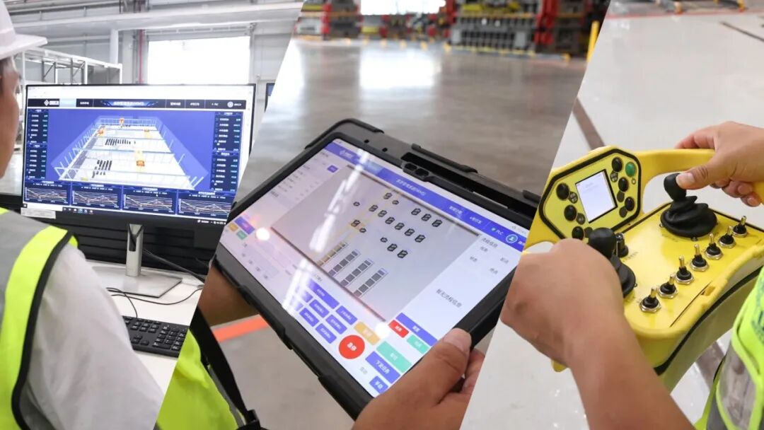
    automotive manufacturing crane operating above workshop equipment
    automotive manufacturing crane operating above workshop equipment
    Project planning notes

    Key points for this crane project.

    1. What Is an Automotive Industry Crane?
    2. Automotive Plant Crane Application Map
    3. Automotive Industry Crane System Architecture
    Read the technical guide

    What Is an Automotive Industry Crane?

    An automotive industry crane is an engineered lifting system used in vehicle plants, component factories and tooling facilities. Typical duties include press-die storage and changeover, mold transfer, steel-coil receiving, body fixture handling, robot and conveyor maintenance, engine and transmission assembly, battery-pack movement, end-of-line service and general plant maintenance.

    One crane type does not serve every automotive zone. A press shop may require a process-duty double-girder die-handling crane with a dedicated gripper and automatic positioning. A body shop may require an underhung or light workstation system around robots and conveyors. A loading edge or workshop extension may be better served by a semi-gantry crane. Capacity, precision, duty and safety architecture are therefore selected by task rather than by industry name alone.

    Henan Mine Crane develops automotive lifting solutions from double-girder bridge crane, European-style single-girder crane, single-girder suspension crane and project-specific automated handling platforms.

    Automotive Plant Crane Application Map

    A plant-wide lifting study records routine production moves, maintenance lifts, emergency recovery tasks and every interface with presses, robots, conveyors, storage systems and vehicle traffic.

    Coil and Blank Receiving

    Unload coils, sheet packs and production materials, then transfer them to storage or blanking lines. Coil orientation, attachment choice, surface protection, aisle clearance and delivery-vehicle exclusion determine the handling concept.

    Press Shop and Die Store

    Retrieve matched die sets, transport them along a protected route and position them at the press or die-change cart. High load, short change windows, offset centers of gravity and controlled seating make this the most demanding automotive crane duty.

    Body-in-White and Welding

    Handle fixtures, welding cells, robots, framing equipment and replacement tooling. Low headroom, crowded services and restricted robot zones often favor underhung, monorail or workstation arrangements.

    Powertrain and E-Drive

    Move engines, transmissions, motors, housings, machining fixtures and test equipment through defined stations. Smooth variable-speed motion, ergonomic controls and application-specific fixtures protect machined surfaces and assembly interfaces.

    Battery and Paint Areas

    Battery-pack assembly, cell production and paint operations have different cleanliness, fire and hazardous-area conditions. The approved environmental and area-classification documents—not the process name—determine enclosure, materials and explosion-protection requirements.

    General Assembly and Maintenance

    Support point-of-use lifting, conveyor work, fixture exchange, line-side replenishment and maintenance shutdowns. Coverage, approach, manual handling risk, parked-load location and unobstructed production flow shape the layout.

    Automotive Industry Crane System Architecture

    Bridge and Runway

    Single- or double-girder, top-running or underhung architecture is selected from capacity, span, headroom, approach, building reactions, process coverage and required stiffness.

    Hoisting Machinery

    Wire-rope hoist or open-winch machinery is sized from gross load, lift, speeds, starts, load spectrum, precision, brake strategy and required production availability.

    Motion and Positioning

    Variable-frequency drives, controlled acceleration, creep speed, encoders, load-height feedback and anti-sway functions support stable travel and repeatable final approach.

    Controls and Plant Interface

    Pendant, radio, cabin or remote-control-room operation can integrate with press controls, WCS, MES, storage management, access gates and maintenance authorization.

    Inspection and Recovery Access

    Walkways, platforms, isolation stations, attachment stands, rescue provisions and component-removal paths are coordinated with production equipment before fabrication.

    Automotive Industry Crane Selection Considerations

    Rated tonnage is only one selection input. The complete load envelope, process sequence and consequence of delayed changeover define the appropriate crane.

    Load Family and Center of Gravity

    Maximum and minimum mass, dimensions, lifting points, center-of-gravity range, surface restrictions and orientation are documented for every die, fixture, component and maintenance load.

    Cycle and Availability

    Die changes per shift, travel path, storage retrieval, press occupancy, average load, starts per hour, annual operating hours and recovery strategy determine mechanism duty and redundancy.

    Placement and Approach

    Required coordinates, allowable approach, final speed, die-cart interface, rack geometry, press centerline and permissible alignment error are specified as measurable acceptance values.

    Building and Process Envelope

    Runway elevation, roof, columns, presses, racks, robots, conveyors, utilities, access doors and neighboring cranes are checked in a coordinated three-dimensional clearance model.

    Control and Data Scope

    Manual, assisted or automatic operation; die identification; task source; station handshakes; protected areas; event records; cybersecurity and manual recovery are defined before controls are priced.

    Environment and Maintenance

    Press-shop vibration, lubricants, welding fumes, dust, heat, washdown, paint solvents, dry-room conditions and scheduled shutdown windows establish the protection and service concept.

    Automotive Industry Crane Configurations Compared

    ConfigurationTypical Automotive DutyPrincipal StrengthCritical Engineering Check
    Automated Die-Handling Process CraneDie store retrieval, press feeding and returnRepeatable high-load transfer with dedicated attachment and plant integrationDie database, grip confirmation, center of gravity, positioning, protected route and safe recovery
    Double-Girder Overhead CraneHeavy dies, molds, presses, fixtures and maintenance loadsHigher capacity, stiffness and available hook height for process-duty handlingDuty class, load share, wheel loads, headroom, attachment mass and final approach
    Single-Girder Low-Headroom CraneComponents, tooling, line maintenance and warehouse serviceCompact general-purpose coverage with lower structural massHoist approach, building reactions, actual duty and attachment clearance
    Underhung or Workstation CraneBody fixtures, powertrain components and point-of-use assemblyFlexible local coverage above crowded production floorsRoof support, joint and suspension loads, ergonomic force, runway layout and end stops
    Semi-Gantry CraneLoading edge, workshop extension and localized machine serviceCoverage where only one side of the building can support an elevated runwayGround rail, building-side reactions, skewing, traffic separation and floor obstruction

    Automotive Press Shop and Die-Handling Crane

    Press-shop availability depends on retrieving the correct die set, engaging it safely, traveling along an authorized route and placing it at the defined interface within the production change window.

    Die Store Retrieval

    The task identifies the die, rack position, mass, center of gravity, approved engagement points and destination. Rack clearances and pickup tolerance are incorporated into the attachment and positioning design.

    Grip and Load Confirmation

    Mechanical position, locking state, contact or pin engagement and load distribution can be monitored before hoisting. A confirmed signal does not override inspection of damaged or obstructed lifting points.

    Protected Transfer

    Position tracking, height limits, anti-sway, collision supervision and protected travel corridors control the movement between storage, inspection, maintenance and press-line stations.

    Press Ready Handshake

    The press, bolster, die cart, clamps, guards and access state must establish an approved transfer condition. The responsibility for each permissive is recorded in the interface matrix.

    Precision Placement

    Creep speed, load-height feedback, anti-sway and attachment adjustment support final alignment without using press equipment, racks or guides as uncontrolled mechanical stops.

    Release and Traceability

    Release is enabled only after support, position and station state are confirmed. Task completion records die identity, source, destination, time, alarms and any manual intervention.

    Automotive Crane Attachments and Load Interfaces

    Die Gripper or Custom Spreader

    A powered gripper or adjustable spreader supports frequent die retrieval where interfaces can be standardized. Selection covers the complete die range, engagement geometry, adjustment axes, locking confirmation, allowable side load, collision envelope and parking stand.

    Attachment deadweight reduces available net load. The crane, attachment and die are therefore evaluated as one suspended system.

    Beam, Sling, Tong, Vacuum Device or Manipulator

    C-hooks or tongs can serve coils and sheet packs. Vacuum devices can handle suitable panels or sheets, while manipulators support ergonomic component positioning.

    Each device requires a declared load range, proof test, inspection criteria and energy-loss response. Surface condition, porosity, oil, curvature and temperature are included where vacuum or magnetic principles are considered.

    Die Turning

    Turning or inversion requires an engineered turning device, two-hook arrangement or dedicated station with defined load share and control sequence. Side pulling, dragging and improvised turnover are excluded.

    Component Protection

    Replaceable non-marking contact pads, controlled clamping force, soft motion profiles and approved support geometry protect machined surfaces, painted parts and precision fixtures.

    Attachment Changeover

    A multi-purpose crane requires a safe connection method, identified services, parking stands, retained capacity, changeover time and recovery procedure for an incomplete connection.

    Capacity, Duty Class and Positioning Performance

    Gross Load and Net Capacity

    Crane rated capacity must cover the heaviest die, mold, fixture or component plus the complete below-the-hook attachment and any suspended auxiliaries. The crane manufacturer accounts for the hook block and reeving within the machinery design. Eccentric centers of gravity and uneven load share are checked separately.

    Duty from the Production Profile

    ISO, FEM or CMAA classification is derived from operating hours, starts, load spectrum, travel, reversing and production consequences. A crane lifting the maximum die only occasionally can have a different duty from a lighter crane cycling continuously on an assembly line.

    Accuracy and Repeatability

    Positioning claims define measurement point, load, speed, axis, repeatability, environmental conditions and acceptance method.

    Performance Data Required

    • Load dimensions, lifting points and center-of-gravity range
    • Lifts per hour, shifts, annual hours and load spectrum
    • Source, destination, travel distance and lift height

    Automation, WCS and Production-Line Integration

    Task and Load Identity

    WCS, MES, barcode, RFID or operator confirmation associates the physical die or component with mass, coordinates, process status and destination. Unidentified or conflicting loads enter a controlled exception state.

    Position and Anti-Sway

    Absolute or referenced coordinates, controlled acceleration, sway reduction, load-height feedback and final approach logic support stable movement without contact-based correction.

    Press and Station Handshake

    Ready, occupied, guarded, clamped, transfer enabled, release authorized, complete and fault states are exchanged with presses, die carts, racks, gates and maintenance systems.

    Protected Areas and Collision Control

    Restricted volumes, temporary maintenance zones, crane-to-crane separation, obstacle detection and speed-limited approaches are implemented under the approved risk assessment.

    Operating Modes

    Automatic, remote, local maintenance and recovery modes have defined authority, speed limits, permissives and transition conditions. Active mode and control ownership remain unambiguous.

    Diagnostics and Recovery

    Event logs, cycles, loads, sensor states and alarms support maintenance. Recovery covers incomplete gripping, lost position, unavailable destination, failed communications and power interruption.

    Safety Functions and Environmental Boundaries

    Suspended-Load Exclusion

    Pedestrian workstations, vehicle lanes and operator positions are kept outside the suspended-load path. Automatic operation uses controlled access and a defined safe state for zone entry.

    Attachment Permissive

    Hoisting and travel permissions can depend on verified engagement, load range and attachment configuration. Release remains inhibited until the load is supported and the destination is authorized.

    Press and Robot Interlocks

    Press motion, robot zones, die-cart travel, clamps, guards and crane movement are coordinated so that conflicting commands cannot create an uncontrolled exposure.

    Overload, Limits and Brakes

    Rated-capacity protection, normal and final motion limits, brakes, buffers, travel warnings and monitored speed zones are selected under the governing code and risk assessment.

    Paint and Solvent Areas

    Explosion-protected equipment is supplied only where the approved hazardous-area classification identifies zones, gas or vapor groups, temperature class and equipment protection requirements.

    Battery Production Boundary

    Cell manufacturing, module assembly and finished-pack handling can have different dry-room, cleanliness, chemical, dust and fire conditions. The site assessment determines the applicable crane package.

    Runway, Building and Maintainability Interfaces

    Existing Building Verification

    Reuse requires verification of rails, runway beams, roof trusses or suspension points, brackets, columns, connections, foundations, fatigue history and measured condition. Maximum and minimum wheel reactions, lateral forces and buffer loads are issued for structural review.

    Clearance and Production Coordination

    Bridge, trolley, attachment and load envelopes are checked against presses, die racks, robots, conveyors, ducts, cable trays, lighting and fire systems. Installation is planned around production shutdowns and protected line areas.

    Maintenance Strategy

    Access platforms, safe parking, isolation, inspection positions, rope and brake service, attachment maintenance and component-removal routes are defined before procurement. Critical spare strategy reflects the production consequence of downtime.

    Site Data Required

    • Rail or suspension-point survey and allowable reactions
    • Press, rack, robot, conveyor and utility envelopes
    • Erection opening, laydown area and shutdown window

    Applicable Standards and Acceptance Testing

    The contract identifies the governing jurisdiction, crane design code, electrical standard and below-the-hook lifting-device rules. Common reference frameworks include ISO 4301 for classification, ISO 9927 for inspections and ISO 12480-1 for safe use; EN 13001 and EN 15011; CMAA 70 or CMAA 74 with applicable ASME B30 requirements; and ASME B30.20 with ASME BTH-1 for relevant lifting devices.

    IEC 60204-32 can govern electrical equipment for hoisting machines, while ISO 13849-1 or IEC 62061 can inform safety-related controls. IEC 60529 addresses enclosure ingress ratings and ISO 12944 can inform coating selection. ATEX, IECEx, NEC or other hazardous-location requirements apply only where the approved project classification establishes that scope. Local law and the signed specification remain controlling.

    Design Review

    Confirm load cases, classification, general arrangement, runway reactions, attachment, die range, placement performance, safety functions, interfaces and maintenance access.

    Factory Acceptance Test

    Verify assemblies, drives, brakes, limits, load protection, attachment logic, safety functions, interface simulation, operating modes, diagnostics and contracted documentation.

    Site and Production Acceptance

    Test proof loads, representative dies, all source and destination stations, cycle time, placement, interlocks, restricted zones, communications loss and manual recovery.

    Published Automotive Mould-Handling Crane Project

    Automated Mould Transfer for an Automotive Stamping Workshop

    Henan Mine Crane reports delivering a customized automated mould-handling crane for a domestic automotive manufacturer. The published scope identifies automatic positioning, WCS management, area protection, obstacle avoidance, a multidirectional special spreader, anti-sway, servo positioning and three operating modes.

    The published safety functions include laser anti-collision, light-curtain area protection, image monitoring and a 3D-vision digital-twin function. The record states that the project was developed for mould transfer in an automotive stamping workshop.

    Automotive Industry Crane Price and Budget Scope

    An automotive crane cannot be priced accurately from capacity alone. Public prices reviewed in 2026 illustrate different supply levels and are not equivalent project quotations.

    Public Market ReferenceMajor Scope Boundary
    Automated Automotive Die-Handling Crane ProjectA valid total requires the die database, layout, duty, cycle, positioning, WCS or MES interfaces, safety scope and destination

    Primary Price Drivers

    Capacity, span and lift; duty class and speeds; die gripper or lifting device; two-hoist or turning requirement; positioning and anti-sway; automatic controls; WCS, MES and press interfaces; safety zoning; building steel; documentation and local compliance.

    Commercial Scope to Reconcile

    Runway rails and steelwork; structural reinforcement; freight, insurance, duties and taxes; erection; electrification; commissioning; test loads; representative dies; line-interface testing; training; spares; warranty and production acceptance.

    Engineering and Procurement Deliverables

    A procurement-ready offer defines measurable performance, interfaces, evidence and commercial boundaries.

    Technical Proposal

    Design basis, crane arrangement, capacities, classification, speeds, attachment, load assumptions, precision, protection package, operating modes and stated deviations.

    Interface Schedule

    Runway reactions, power, communications, press and station I/O, coordinates, safety ownership, erection needs, civil boundaries and third-party responsibilities.

    Attachment Documentation

    Rated range, deadweight, dimensions, engagement, locking logic, proof test, inspection limits, wear parts, attachment stand and representative-load acceptance plan.

    Safety and Controls

    Risk-assessment inputs, safety-function list, restricted zones, interlock matrix, network behavior, isolation, emergency states, recovery and required conformity records.

    Quality and O&M Records

    Inspection and test plan, material and welding records as specified, coating reports, component certificates, manuals, lubrication plan, training and critical spares.

    Commercial Schedule

    Price, Incoterm, milestones, packing, freight boundary, installation, commissioning, training, acceptance, warranty, exclusions, validity and optional lifecycle services.

    Automotive Industry Crane RFQ Information

    The following data supports a configuration-based technical and commercial proposal.

    Load and Attachment Data

    Load families; minimum and maximum mass; dimensions; center of gravity; lifting points; orientation; surface restrictions; photographs or drawings; proposed gripper, beam, tong, C-hook, vacuum device or rigging.

    Process and Duty Data

    Source and destination stations; changeover sequence; lifts per hour; shifts; annual hours; load spectrum; travel distance; target cycle; placement tolerance; availability and contingency.

    Site and Environment Data

    Span, lift, runway length, building and process drawings, allowable reactions, press and rack interfaces, temperature, dust, welding, paint, clean or dry-room requirements, power and destination.

    Controls and Commercial Data

    Operating modes; WCS, MES and PLC protocols; task and die identity; safety zones; governing standards; Incoterm; freight, installation, commissioning, test and documentation boundaries.

    Frequently Asked Questions

    Which crane is used in an automotive press shop?

    A process-duty double-girder overhead crane is commonly selected for heavy die storage and changeover. A dedicated die gripper, anti-sway, precision motion and press-line interfaces may be added when cycle frequency and automation justify them.

    Is one crane suitable for the entire automotive plant?

    Usually not. Press dies, body fixtures, powertrain components, assembly tasks and maintenance loads differ in mass, frequency, precision and environment. A plant-wide lifting plan assigns a suitable crane class to each zone.

    How is die-handling crane capacity determined?

    Capacity covers the heaviest die plus the complete gripper, beam or other below-the-hook device. Center of gravity, load share, acceleration, turning requirements and governing code are then applied.

    Can the crane retrieve dies automatically?

    Automatic retrieval can combine a die database, WCS tasks, position tracking, a dedicated gripper, anti-sway, protected zones and press handshakes. Safe exception handling and manual recovery remain mandatory design elements.

    Does an automotive crane need millimetre-level positioning?

    Only where the actual station and attachment require it. The purchase specification defines the measurement point, load, speed, repeatability and acceptance method rather than using an unsupported general accuracy claim.

    Are explosion-proof cranes required in paint shops?

    Only when the approved hazardous-area classification establishes the relevant zone and protection requirements.

    How much does an automotive industry crane cost?

    Public figures range from crane-only estimates and component kits to complete support systems. A defensible project price requires capacity, span, duty, attachment, automation, plant interfaces, building scope, destination and acceptance criteria.

    Can an existing runway be reused?

    Only after geometry, condition, fatigue history, rails, beams, columns, connections and foundations are verified against the proposed vertical, lateral, longitudinal and buffer reactions.

    Related Automotive Industry Crane Products

    Select the crane platform according to the load, working area, building structure, duty cycle, positioning requirement and production interface.

    Double-Girder Bridge Crane

    Heavy-duty overhead platform for press dies, large fixtures, tooling and maintenance loads.

    European-Style Electric Single-Girder Crane

    Compact crane for automotive components, tooling, warehouses and planned line maintenance.

    Single-Girder Suspension Crane

    Underhung coverage for body, assembly and maintenance areas with suitable roof support.

    Single-Girder Overhead Crane

    Top-running bridge crane for general component handling, tooling support and workshop service.

    Intelligent Electric-Hoist Crane

    Low-headroom electric-hoist platform with controlled-motion and digital monitoring options.

    Semi-Gantry Crane

    Localized handling for loading edges, workshop extensions and production-support zones.

    Submit the load or die schedule, attachment concept, handling sequence, cycle and positioning requirements, span, lift, runway and plant drawings, operating environment, control level, WCS or MES interfaces, safety zones, power supply, project destination and supply boundary. Henan Mine Crane will prepare a configuration-based technical and commercial proposal.

    Discuss the crane arrangement for your project.

    Automotive plants need lifting support for different tasks rather than one universal crane specification. Identify the handled tools or components and their movement sequence so crane arrangements can be matched to each work area. Share the load, available drawings, working cycle and site conditions with Henan Mine Crane so the required configuration and supply boundary can be discussed.

    Related crane configurations

    Explore crane product families and technical parameters ↗

    Updated 2026 · Henan Mine Crane

  • Automotive Assembly Cranes: Positioning and Line-Side Handling

    Automotive Assembly Cranes: Positioning and Line-Side Handling

    Selection guide

    Automotive Assembly Cranes: Positioning and Line-Side Handling

    Assembly lifting needs to fit the component presentation and production sequence. Define lifting points, required orientation and handover positions so the crane and surrounding equipment can be reviewed as one handling process.

    Henan Mine CraneSelection guide · Updated 2026Crane selection, project scope and operating requirements
    Modular electric-hoist overhead crane for workshop handling
    Modular electric-hoist overhead crane. Illustrative equipment configuration; the assembly-line arrangement is specified for the project.
    Project planning notes

    Key points for this crane project.

    1. What an Automotive Assembly Crane Has to Do
    2. Where Cranes Work in an Automotive Plant
    3. Crane Configurations for Assembly Service
    Read the technical guide

    What an Automotive Assembly Crane Has to Do

    An automotive assembly crane is a lifting system engineered to keep pace with a production line rather than simply to move a load. In a vehicle plant, the crane is part of the process: it feeds stamping presses with dies, positions body panels and fixtures in the body shop, moves engines, transmissions and axles onto machining and marriage stations, supplies parts to assembly stations alongside the line, and supports maintenance and end-of-line operations. What separates these cranes from general workshop cranes is not usually tonnage — it is cycle profile, positioning accuracy, ergonomics and integration with the surrounding production equipment.

    Assembly duty is defined by the takt time of the plant. A station that produces a vehicle every sixty seconds cannot wait on an uncontrolled crane swing or a hoist that creeps into position. Smooth stepless speed control, anti-sway behaviour, repeatable positioning and fast but gentle load handling directly determine whether the crane supports the line or bottlenecks it. At operator workstations, low operating forces and precise inching control also decide whether lifting assists the process or becomes an ergonomic and quality problem.

    Automotive plants also impose strict building constraints. Conveyor lines, skid systems, automation cells and process equipment occupy the volume under the roof, so hook coverage, headroom, rail clearances and interference with existing steelwork often eliminate crane configurations long before price is discussed. The correct approach is to match the crane family to the area of the plant and the measured duty at each lifting point.

    Henan Mine Crane supplies automotive assembly cranes as engineered packages: bridge or suspended structure, hoist and travel machinery, control and positioning systems, runway or suspension interface, safety functions and documentation — configured against the takt time, load spectrum, accuracy and building interface of the specific line.

    Where Cranes Work in an Automotive Plant

    Press and Stamping Shop

    Double girder cranes change and transfer press dies, handle coil and blank feeding equipment and support press maintenance. Die handling is slow, precise, high-value lifting where hook approach, exact load control and reliability matter more than speed.

    Body-in-White Shop

    Cranes install and exchange welding fixtures, position body panels and subframe assemblies, and serve framing stations. Coverage must work around robots and conveyor steel, and every lift position has to repeat within the fixture tolerances of the station.

    Powertrain Machining and Assembly

    Engines, transmissions, cylinder heads and crankshafts are handled between machining cells, washing and test stations. These areas combine moderate loads with high cycle counts and demand controlled, gentle set-down on machined surfaces.

    Final Assembly Line-Side Supply

    Suspended and workstation crane systems feed seats, doors, batteries, fuel tanks, dashboards and powertrain units to the stations that install them. Low headroom, ergonomic effort levels and reach into the station without intruding on the line are the defining requirements.

    Paint Shop and Utilities

    Cranes maintain dipping, drying and treatment equipment, handle skids and carriers, and support the process tanks and ovens that run continuously. Environment class, enclosure protection and maintenance access drive the specification in this area.

    Maintenance and End-of-Line Operations

    Workshop and workstation cranes support equipment repair, test bays, wheel and headlamp alignment areas and general logistics. These cranes lift infrequently but must be available on demand, since downtime in a running plant is measured in lost vehicles per hour.

    Crane Configurations for Assembly Service

    Each production area favours a different crane family. The selection below shows how the configuration follows the load, the cycle and the building — and where each option earns or loses money over the life of the line.

    European-style single girder cranes raise this baseline with FEM-oriented duty design, lower dead weight, better hook approach and smoother travel — the standard choice where high cycle counts, close tolerances or restricted building capacity apply.

    Where loads grow — press dies, skid systems, powertrain modules, complete fixtures and maintenance of heavy process equipment — double girder cranes take over, adding hook height, stiff long-travel behaviour and heavy-duty hoisting machinery. Double trolley versions handle long and flexible parts such as shafts, axles, rail segments and long weldments that would overload a single hook point or distort during lifting.

    Suspended underhung systems bolt to the building roof steel instead of running on elevated runway rails, so they reach into stations at low headroom with minimal steelwork. Multi-point suspension designs cover wide or irregular bays. Intelligent hoist cranes close the loop with controlled positioning, anti-sway and operator guidance for the highest-accuracy stations.

    Automotive Assembly Crane Selection Considerations

    Selection begins with the production process and works outward to the crane. The parameters below establish the specification that a quotation must be built against, and the checklist that competing offers are compared on.

    List every load at every lifting point with its fixture, spreader or tooling weight. The heaviest combination at the busiest station — not the average — sets the rated capacity for the whole system.

    Convert line takt into lifts per hour, travel distances and full-load ratio per station. These numbers set the ISO duty class of hoist, trolley and travel mechanisms — the difference between a line-speed crane and an early failure.

    Define the positioning tolerance at each station and the acceptable residual sway at set-down. These requirements select between standard speed control, frequency inverter control with crawl steps, and closed-loop anti-sway positioning.

    Confirm clear height, roof steel capacity, existing conveyor and utility positions, and the clearance the process needs below the hook. Low buildings push the specification towards top-running, double girder or suspended configurations.

    Paint shops, clean zones and battery areas impose dust, temperature and contamination limits on motors, brakes and controls. The enclosure and protection class is specified per area, not per building.

    Define interlocks with conveyors, robots, skid systems and safety circuits, the control positions operators will use, and any interface to plant PLC or monitoring systems. Integration scope changes the electrical boundary of the offer.

    Where operators handle loads manually, specify the permissible operating force, the reach envelope into the station and the precision of inching control. Ergonomic limits are production limits on an assembly line.

    Assign runway or suspension steel, conductor systems, installation, commissioning, load testing, spares and certification in writing before comparing offers, and state the standards the documentation must satisfy for the plant’s market.

    Automotive Assembly Crane Configurations Compared

    The most suitable configuration serves the takt time and accuracy of the station without transferring unnecessary cost into the building structure or the maintenance schedule.

    ConfigurationWhere It Fits BestPositioning Behaviour
    Single girder bridge craneGeneral assembly, machining support, logistics baysGood with inverter control and crawl steps
    European-style single girder craneHigh-cycle assembly stations, tight-tolerance areasSmooth FEM-oriented travel, close hook approach
    Double girder bridge cranePress shops, powertrain, skid systems, heavy fixturesStiff travel, maximum hook height, precise heavy lifts
    Double trolley craneLong parts — shafts, axles, rails, weldmentsSynchronised two-point lifting without distortion
    Suspended underhung systemLine-side supply at stations, low-headroom baysLight, ergonomic, direct reach into the station
    Intelligent hoist craneHighest-accuracy stations, controlled processesClosed-loop positioning with anti-sway

    Automotive Assembly Crane Technical Specification Framework

    Henan Mine Crane maintains several crane families applied to automotive production service. The ranges below support preliminary configuration and are not guaranteed combinations. Final capacity, span, lift, working class, speeds and wheel loads are confirmed on the approved technical schedule and general arrangement drawing.

    A capacity shown within one family does not confirm suitability at every span, lift or duty. Long spans, high cycle counts, precision requirements and integration with line controls require project-specific calculations and verification.

    Building and Runway Interface

    An automotive plant is a dense steel environment. The crane succeeds or fails at its interfaces with the building, and every one of these points has to be resolved before manufacture begins.

    Wheel Loads and Rail Seats

    Maximum and static wheel loads, with and without load, are verified against the runway beams and building columns. A crane change on an existing runway always starts with this check, not with the catalogue.

    Suspended Loads on Roof Steel

    Underhung and multi-point suspension systems hang from the building structure. The roof steel capacity, bracing positions and allowable deflection decide whether suspension is viable and how the load paths are arranged.

    Clearance to Conveyors and Automation

    Hook coverage is mapped against conveyors, skid tracks, robot cells and process tanks. The crane must reach the defined pick-up and set-down points without entering protected volumes or intruding on safety zones.

    Power Feed and Conductor Systems

    Conductor bars or festoon systems are routed along the runway with isolation, earthing and maintenance positions defined. Power feed placement affects plant electrical layout and must be fixed early in the project.

    Controls, Positioning and Line Integration

    Control selection follows the accuracy and rhythm of the station. The same crane structure can behave completely differently under pendant, radio or programmable control, and the difference shows directly in cycle time and damage rates.

    Pendant and Radio Control

    Pendant control keeps the operator at a fixed position beside the load; radio remote frees them to watch the load and the station. On assembly stations, radio control is usually the more productive and safer choice.

    Frequency Inverter Travel and Hoist

    Stepless speed control with defined acceleration and crawl steps lets the operator place loads without shock. On machined powertrain components, controlled set-down is a quality requirement, not a comfort feature.

    Anti-Sway and Positioning Control

    Closed-loop anti-sway and target positioning reduce swing, shorten waiting at the station and protect fixtures and parts. Encoder feedback and slow-approach zones place the hook within repeatable tolerances cycle after cycle.

    Interlocks and Plant Systems

    Where cranes share space with conveyors, robots or skid systems, interlocks, zone limits and signal exchange with the plant controller are engineered into the crane control. The interface scope belongs in the contract, not in site improvisation.

    Duty Class and High-Cycle Assembly Reliability

    Assembly cranes run many small cycles per shift for years. Reliability comes from matching mechanism classifications, brakes and structure to the measured duty — and from designs that can be maintained inside production windows.

    The Default Duty Trap

    Many general-purpose offers are built to infrequent-use classifications. On a station cycling every takt, those mechanisms consume their design life early. Duty class must be specified from the measured cycle profile, never left to the supplier default.

    Fatigue and Structural Allowance

    High-cycle welding details, wheel and rail contact and brake engagement counts are fatigue items. The structure is engineered for the number of cycles the line will actually run, not for a nominal tonnage figure.

    Maintenance-Friendly Design

    Wear parts, brakes and limit systems are arranged for fast access inside short production breaks. Maintenance positions and inspection routes are defined at design stage, because unplanned line stops cost vehicles, not minutes.

    Documentation and Testing

    Structural calculations, test certificates, overload and static load test reports and defined acceptance criteria support commissioning and the plant’s own safety and audit systems. Documentation scope is agreed before production starts.

    Engineering and Supply Scope for Assembly Plant Projects

    An automotive assembly crane project typically covers several crane families at once: standard and European-style single girder cranes for line-side and machining areas, double girder cranes for the press shop and powertrain, and suspended systems feeding the final assembly stations. Henan Mine Crane plans such projects around a common engineering baseline, so that control behaviour, spares and documentation stay consistent across the different areas of the plant.

    A complete supply definition states the crane structure and machinery, the hoist and control system, the runway or suspension interface, conductor systems, the safety functions required at each station, the overload and acceptance testing regime, and the delivery, installation and commissioning responsibilities. Where the plant’s own engineering team installs, supervision, commissioning and load testing remain part of the package.

    Standard configurations are typically delivered within 30 to 45 days after drawing approval, with engineered or automation-equipped cranes on confirmed project schedules. Multi-crane programs are sequenced against the plant’s shutdown and ramp-up calendar.

    Automotive Assembly Crane Price Reference

    Current market positions for Chinese-manufactured crane equipment, expressed as indicative ranges. An equipment price covers the crane ex-works; an installed project adds runway or suspension steel, conductor systems, freight, duty, installation and commissioning.

    Crane ScopeWhat Moves the Number
    Suspended workstation systemRail length covered, number of bridges, hoist grade
    Line-side monorail or suspended craneTrack routing, switches, curves, suspension points
    Single girder assembly craneSpan, lift height, hoist grade, control mode
    European-style single girder craneDuty rating, low-headroom design, speed control level
    Double girder assembly and powertrain craneSpan, dual speed levels, cabin or radio control
    Press shop die handling craneSpan, slow precise speed ratios, special duty build
    Runway and rail packageBay length, rail profile, structural reinforcement
    Freight, duty and installationDestination, installation scope, local certification

    Comparing offers on an equipment price alone understates the real decision. Normalize every quotation to the same supply boundary — capacity including fixtures, span, lift, control mode and speed levels, conductor systems, installation, testing and documentation — before comparing numbers.

    Quote Information and Frequently Asked Questions

    A complete enquiry should state the production area, the loads at each lifting point including fixtures and tooling, takt time, required positioning accuracy, building dimensions and roof steel condition, power supply, destination and the required supply boundary.

    Load and Station Data

    Part weights with fixtures and tooling at every lifting point, heaviest combination, lift frequency per station and the full production shift pattern.

    Building and Geometry Data

    Clear height, span or rail centers, travel lengths, roof steel or runway capacity, conveyor and automation positions, and the hook coverage each station requires.

    Process and Accuracy Data

    Positioning tolerance at set-down, acceptable residual sway, required speeds and inching behaviour, and any interlocks with conveyors, robots or plant systems.

    Commercial and Site Data

    Voltage and frequency, destination and Incoterm, installation responsibility, required certifications and documentation, spares level and requested delivery schedule.

    What crane does an automotive assembly plant use?

    Assembly plants use a combination of systems: single and European-style single girder bridge cranes for line-side and machining areas, double girder cranes for press shops and powertrain handling, double trolley cranes for long parts, and suspended workstation systems for ergonomic part supply at stations.

    How is an assembly crane different from a standard workshop crane?

    The difference is duty and control, not just tonnage. Assembly cranes are classified for high cycle counts tied to takt time, use stepless speed control with crawl and anti-sway behaviour for repeatable positioning, and integrate with conveyors, robots and plant safety systems.

    Can the crane work with conveyors and robots in the same bay?

    Yes, when it is engineered that way. Hook coverage is mapped against conveyor and robot positions, zone limits and interlocks are built into the crane control, and signal exchange with the plant controller is defined in the interface specification before manufacture.

    What is the delivery time?

    Standard configurations are typically delivered within 30 to 45 days after drawing approval. Cranes with anti-sway positioning, line integration or multi-crane program sequencing run on confirmed project schedules agreed before production starts.

    Related Crane Products for Automotive Production

    Product selection follows the approved load spectrum, cycle profile, accuracy requirement and building interface of each production area. Each linked model represents a separate configuration platform.

    European Style Electric Single Girder Crane

    FEM-oriented single girder platform for high-cycle, close-tolerance assembly stations with smooth travel and low dead weight.

    Double Girder Bridge Crane

    Heavy-duty platform for press shop die handling, powertrain modules, skid systems and maintenance of large process equipment.

    Multi-Point Suspension Crane

    Roof-suspended crane system reaching into assembly stations at low headroom without elevated runway steel.

    Intelligent Electric Hoist Overhead Crane

    Smart hoist crane platform with controlled positioning, monitoring and operator guidance for the highest-accuracy stations.

    Double Trolley Electric Hoist Overhead Crane

    Two coordinated trolleys for lifting long parts such as shafts, axles and long weldments without overload or distortion.

    Get an Automotive Assembly Crane Engineered for Your Line

    Send the station loads, takt time and building dimensions and receive a configured proposal with duty classification, control system, interface definitions, documentation and a delivery schedule for your production area.

    Discuss the crane arrangement for your project.

    Assembly lifting needs to fit the component presentation and production sequence. Define lifting points, required orientation and handover positions so the crane and surrounding equipment can be reviewed as one handling process. Share the load, available drawings, working cycle and site conditions with Henan Mine Crane so the required configuration and supply boundary can be discussed.

    Related crane configurations

    Side-Mounted Single-Girder Crane

    View product parameters
    Lifting capacity: 1t – 10tSpan: 7.5m – 28.5mLifting height: 6m – 20m

    Position the electric hoist beside the single-girder bridge with an LDP side-mounted arrangement. Coordinate hook approach, available headroom and the work area around the building structure.

    Updated 2026 · Henan Mine Crane

  • Automated Warehouse Stacker Cranes: Storage Geometry and Transfer Control

    Automated Warehouse Stacker Cranes: Storage Geometry and Transfer Control

    Selection guide

    Automated Warehouse Stacker Cranes: Storage Geometry and Transfer Control

    A stacker crane must suit the load units and storage system around it. Define aisle geometry, transfer positions and recovery access before comparing motion, positioning and control arrangements.

    Henan Mine CraneSelection guide · Updated 2026Crane selection, project scope and operating requirements
    Automated Warehouse Stacker Crane
    Automated Warehouse Stacker Crane
    Project planning notes

    Key points for this crane project.

    1. Automated Stacker Crane for High-Bay Warehouse Operations
    2. Automated Warehouse Stacker Crane Applications
    3. Automated Warehouse Stacker Crane Specifications
    Read the technical guide

    Automated Stacker Crane for High-Bay Warehouse Operations

    An automated warehouse stacker crane travels on a fixed aisle rail, positions a lifting carriage at the required rack level and transfers pallets, totes, containers or special load carriers between storage locations and conveyor interfaces. A coordinated control system manages long travel, vertical lifting and fork movement as one automated storage-and-retrieval cycle.

    The machine forms part of a complete AS/RS rather than operating as isolated lifting equipment. Rack tolerances, rail alignment, conveyor handshakes, load identification, WMS/WCS task logic, safety zoning and recovery procedures are defined as system interfaces during engineering.

    Equipment boundary: An AS/RS stacker crane retrieves unit loads inside rack aisles. It is a different equipment category from an overhead warehouse crane, which handles suspended industrial loads across an open bay.

    Automated Warehouse Stacker Crane Applications

    Pallet High-Bay Storage

    Automated inbound, storage, relocation and outbound handling for standardized pallets in high-density rack systems.

    Tote and Container Storage

    Lightweight configurations for totes, bins, containers and smaller load units requiring compact aisle geometry and frequent cycles.

    Production Buffer Warehouses

    Controlled storage between manufacturing processes, with task exchange between production planning, conveyors and warehouse control.

    Special Load-Carrier Systems

    Project-specific forks, supports, sensors and transfer logic for non-standard carriers, containers or process fixtures.

    Automated Warehouse Stacker Crane Specifications

    The stacker crane specification is developed from the complete warehouse operating model. Final values are stated in the approved technical schedule, interface documents and acceptance plan.

    SpecificationProject DefinitionEngineering Significance
    Load unitPallet, tote, container or special carrier dimensions, payload, centre of gravity and stabilityDefines carriage, fork, clearance, sensor and support requirements
    Rated payloadMaximum and typical load, including carrier and handling-device interfacesEstablishes structural, drive, braking and transfer demand
    Warehouse geometryStorage height, aisle length and width, rack levels, interface positions and maintenance zonesDefines mast arrangement, rail path, travel envelope and hook-up points
    Load handling deviceFork type, extension depth, transfer direction, stroke, support surface and load detectionControls rack interface, cycle time and transfer protection
    Throughput and dutyInbound and outbound rate, single and dual cycles, peak profile, operating hours and load distributionDetermines speed, acceleration, motor duty, availability strategy and machine quantity
    Motion performanceTravel, lift and fork speeds, acceleration, settling time and positioning criteriaConnects throughput with structural response and rack-level transfer accuracy
    Control interfacesWMS, WCS, PLC, network, conveyor handshake, barcode or RFID and data recordsDefines command ownership, status exchange, traceability and recovery logic
    Environment and serviceTemperature, humidity, dust, fire strategy, access, spare parts and availability targetDefines component protection, maintenance concept and lifecycle support scope

    Selection Considerations

    Carrier and Payload Definition

    Load-unit dimensions, weight range, centre of gravity, underside geometry, stability and allowable overhang establish the transfer interface.

    Storage Geometry and Tolerances

    Rack elevations, aisle length, transfer clearances, rail alignment, guide tolerances and maintenance access determine the machine envelope.

    Cycle Model and Peak Demand

    Single-cycle, dual-cycle and peak task profiles establish motion performance, machine quantity, buffering and availability requirements.

    Fork Depth and Handover

    Single-depth, double-depth and special transfer arrangements require different fork stroke, detection, support and cycle-time calculations.

    Automation Responsibility

    The interface schedule assigns WMS, WCS, PLC, network, identification, conveyor, cybersecurity and acceptance-testing responsibilities.

    Availability and Recovery

    Maintenance access, diagnostic depth, spare parts, recovery procedures and redundancy are aligned with the required system availability.

    Automated Warehouse Stacker Crane Compared with Other Warehouse Handling Configurations

    Configuration selection is based on the same load-unit data, storage geometry, throughput model, control boundary and availability target. Equipment cost is evaluated together with rack density, aisle quantity, transfer stations, software integration and lifecycle access.

    ConfigurationOperating ArrangementApplication FitCritical Procurement Criteria
    Single-Column Stacker CraneOne mast supports the lifting carriage and handling deviceSuitable payload, storage height and dynamic duty where lower machine mass and a compact aisle are prioritiesMast deflection, carriage guidance, acceleration, settling time and maintenance access
    Double-Column Stacker CraneTwo columns provide a guided structural frame for the carriageHeavier loads, taller storage, higher stiffness demand or intensive operating cyclesMachine envelope, rail loads, structural stiffness, energy demand and service access
    Track-Switching or Turnout SystemA machine transfers between compatible aisle rail pathsMultiple aisles where the throughput model supports shared equipment and transfer timeSwitch geometry, route availability, control interlocks, recovery access and capacity during maintenance
    Conventional Forklift StorageOperator-driven mobile handling within warehouse aislesFlexible layouts, lower automation requirements and applications where manual traffic is acceptableAisle width, storage height, labour, traffic management, inventory accuracy and long-term operating cost
    Overhead Warehouse CraneSuspended-load lifting across an open warehouse bayMachinery, steel, tooling and industrial goods that require overhead hook coverage rather than rack-aisle retrievalBuilding support, hook coverage, lifting attachment, duty and interaction with racks or traffic

    Automated Storage and Retrieval Operating Cycle

    A complete cycle combines material-flow commands, equipment status, load identification and controlled motion. The operating sequence is configured to match the warehouse software architecture and the physical interfaces at every storage and transfer position.

    Task Release

    The warehouse system releases a validated storage, retrieval or relocation task with the required load and destination data.

    Load Handover

    Conveyor and stacker-crane controls confirm load identity, position, readiness and transfer permission before movement begins.

    Coordinated Travel

    Long travel and lifting are coordinated to approach the assigned rack location while controlling structural response and settling time.

    Protected Transfer

    Position and occupancy conditions are checked before the fork extends, transfers the load and returns to its travel position.

    Status Confirmation

    Completion, location and equipment status are returned to the control hierarchy for inventory records and the next task assignment.

    Structural Configurations Engineered for the Storage System

    Single-Column and Double-Column Designs

    Single-column construction can reduce moving mass and support compact aisle arrangements when payload, storage height and dynamic behaviour permit. Double-column construction provides a framed carriage guidance arrangement for applications requiring greater stiffness, heavier load handling or demanding operating cycles.

    The final structure is selected through load analysis, aisle geometry, dynamic response, positioning requirements, drive duty and maintainability. Lightweight box-type structural members may be applied where mass reduction and rigidity must be balanced.

    Fixed-Aisle, Track-Switching and Turnout Arrangements

    A fixed-aisle stacker crane provides dedicated access and predictable capacity within one aisle. Track-switching and turnout arrangements allow a compatible machine to serve more than one aisle when the throughput calculation, route availability and recovery strategy support shared equipment.

    Multi-aisle operation requires coordinated route control, transfer-position interlocks and a capacity assessment covering both normal production and planned maintenance conditions.

    High-Speed Motion, Anti-Sway Control and Precise Positioning

    Warehouse throughput depends on more than maximum speed. Acceleration, deceleration, structural response, settling time and final transfer accuracy must work together across the full aisle and lifting range. Henan Mine Crane applies static and dynamic finite-element analysis to evaluate structural behaviour and support the selected motion profile.

    Controlled Dynamic Response

    Motion profiles and anti-sway control reduce unnecessary oscillation during travel and lifting, supporting shorter settling time and stable approach to the target rack position.

    Rack-Level Positioning

    Position feedback, controlled approach and transfer permissives align the carriage and fork with the assigned storage or handover point before load movement is authorized.

    Performance definition: Travel speed, lift speed, fork cycle, acceleration and positioning criteria are confirmed from the throughput model, rack tolerances, payload behaviour and required machine availability. They are not treated as isolated catalogue values.

    Fork Transfer and Load Protection

    The load-handling device is specified from the carrier underside, storage depth, support arrangement, permitted clearances and transfer direction. Single-depth, double-depth and special telescopic solutions require different fork strokes, deflection control, detection logic and cycle calculations.

    • ✓Transfer authorization based on machine position, fork status and interface readiness
    • ✓Fork anti-push-off protection for controlled handling at the rack location
    • ✓Load-presence and storage-position conditions integrated into the project control logic
    • ✓Protected transition between storage racks, stacker crane and conveyor handover stations

    Space Utilization and Energy Management

    A rigid-flexible column concept and compact equipment envelope can support high-density storage where the structural calculation, rack geometry and service clearances permit. The layout is coordinated with the aisle rail, top guidance, maintenance access, buffer conveyors and fire-protection strategy.

    An optional energy-feedback module can return regenerative energy produced during lowering and deceleration to the electrical system. Its application is assessed against motion frequency, load profile, electrical architecture and project energy objectives.

    WMS, WCS, PLC and Conveyor Integration

    System integration is defined through an interface schedule covering command ownership, data exchange, equipment handshakes, alarm handling, operating modes and recovery procedures. Responsibility boundaries are established before software development and verified during staged testing.

    System LayerPrimary FunctionInterface Definition
    WMSInventory, location and warehouse-task managementTask identifiers, load data, origins, destinations, completion status and exception records
    WCSMaterial-flow coordination and equipment task dispatchQueue logic, route selection, interface availability, task priority and recovery coordination
    Stacker Crane PLCMachine sequence, motion control, interlocks and diagnosticsTask acceptance, operating permission, position, load status, alarms and machine state
    Conveyor and IdentificationPhysical handover and load verificationReady/busy signals, load presence, transfer permission, barcode or RFID data and mismatch handling
    Operator and Maintenance InterfaceStatus visibility, permitted control and diagnostic supportUser roles, alarm history, manual modes, reset conditions, maintenance functions and event records

    Safety, Interlocks and Controlled Recovery

    Safety functions are established through the project risk assessment, equipment layout and operating concept. The control philosophy separates normal automatic operation, authorized manual functions, maintenance access and fault recovery.

    Motion Interlocks

    Travel, lifting and fork movements are permitted only when the defined machine and interface conditions are satisfied.

    Transfer Protection

    Position, load and handover signals are evaluated before rack or conveyor transfer, with fork anti-push-off protection integrated into the sequence.

    Access Control

    Fenced zones, access points and maintenance procedures are coordinated with the warehouse layout and applicable project requirements.

    Fault Recovery

    Alarm classification, safe reset conditions, manual recovery steps and responsibility boundaries are documented for service personnel.

    Engineering, Manufacturing and Project Documentation

    Henan Mine Crane developed its intelligent stacker-crane platform jointly with the Beijing Research Institute of Hoisting and Conveying Machinery. Product engineering combines warehouse-layout coordination, static and dynamic structural analysis, motion-control development, load-transfer design and system-interface definition.

    Project Engineering

    Layout review, equipment boundary, performance calculation, interface schedule, structural verification and maintainability assessment.

    Manufacturing Control

    Fabrication, assembly, drive installation, electrical integration and inspection are managed against the approved project specification.

    Technical Deliverables

    Agreed drawings, parameter schedules, interface records, operating information, maintenance documentation and acceptance records.

    Manufacturing capabilities and production resources are available on the Henan Mine Crane factory page.

    Installation, Commissioning and Acceptance

    Interface Readiness

    Rail, rack, power, network, conveyor, identification and access conditions are checked against approved interface data.

    Mechanical and Electrical Setup

    Machine alignment, guidance, drives, sensors, control panels and communication links are installed and verified.

    Functional Commissioning

    Operating modes, motion, positioning, fork transfer, interlocks, alarms and system handshakes are commissioned in stages.

    Performance Acceptance

    The agreed test plan verifies functions, interfaces, representative load handling, throughput conditions and recovery procedures.

    Acceptance criteria, test loads, test data, operating conditions, attendance and responsibility boundaries are stated in the contract documentation before site testing.

    Maintenance and Lifecycle Support

    Maintenance planning begins during layout and equipment engineering. Safe access, inspection points, component replacement paths, diagnostic information and recovery procedures are coordinated with the required operating availability.

    Inspection Planning

    Scheduled checks aligned with duty, environment, critical assemblies and operating records.

    Diagnostics

    Alarm history, status information and defined troubleshooting paths support structured fault isolation.

    Spare Parts

    Recommended commissioning, operational and critical spares can be defined from the service strategy.

    Training

    Operating, maintenance and recovery training can be included within the agreed delivery scope.

    Information Required for an Automated Stacker Crane Proposal

    A technically comparable proposal requires a defined warehouse operating basis. Preliminary data may be used for concept development, followed by an approved interface schedule for detailed engineering.

    Load and Carrier Data

    Dimensions, maximum and typical weight, centre of gravity, underside arrangement, stability, overhang and identification method.

    Rack and Building Layout

    Storage height, aisle length and width, rack levels, storage depth, rail path, top guidance, transfer stations and service zones.

    Throughput Model

    Inbound and outbound rates, single and dual cycles, peak duration, task distribution, working hours and availability target.

    System Interfaces

    WMS/WCS architecture, PLC and network requirements, conveyor handshakes, barcode or RFID, data ownership and cybersecurity conditions.

    Site Conditions

    Installation location, temperature, humidity, dust, electrical supply, fire strategy, access restrictions and applicable regulations.

    Delivery Boundary

    Equipment, rails, controls, software, conveyors, installation, commissioning, testing, training, documentation and spare-parts scope.

    Automated Warehouse Stacker Crane FAQ

    What is an automated warehouse stacker crane?

    It is a rail-guided storage and retrieval machine that travels within a warehouse aisle, lifts a carriage to rack level and transfers unit loads between storage locations and material-flow interfaces under automatic control.

    When is a single-column design appropriate?

    Single-column construction may be selected when the payload, storage height, stiffness, motion profile and service-access requirements support a lighter and more compact structure. Engineering verification determines its suitability.

    Can one stacker crane serve multiple aisles?

    Track-switching or turnout configurations can serve compatible aisle paths. The decision requires verification of transfer time, route availability, peak throughput, recovery access and capacity during maintenance.

    Does the stacker crane connect with an existing WMS or WCS?

    Integration can be developed around an existing warehouse software environment when protocols, task ownership, data fields, alarm handling, network conditions and testing responsibilities are defined in the interface schedule.

    How is stacker-crane throughput determined?

    Throughput is calculated from aisle geometry, storage-location distribution, transfer time, travel and lift motion, fork cycle, buffering, single and dual cycles, peak demand and equipment availability. Maximum travel speed alone does not define system capacity.

    Which load data are essential for fork selection?

    Required data include carrier dimensions, payload range, underside geometry, support positions, centre of gravity, stability, overhang, storage depth, permitted clearance and transfer direction.

    Can energy recovery be included?

    An optional energy-feedback module can recover regenerative energy during lowering and deceleration. Feasibility depends on the motion profile, operating frequency, load distribution and facility electrical system.

    What determines the final stacker-crane price?

    Major cost drivers include payload, storage height, aisle length, machine quantity, structural configuration, fork depth, performance, control scope, software interfaces, site conditions, installation, testing, training and spare-parts requirements.

    Related Warehouse and Material Handling Cranes

    Electric Single Girder Cranes

    Overhead lifting for workshops, warehouse bays and general industrial load handling. View Product Category →

    Double Girder Overhead Cranes

    Higher-capacity and demanding-duty overhead crane systems for industrial facilities. View Product Category →

    Suspended Overhead Cranes

    Under-running lifting systems for buildings where runway support and floor use require a suspended arrangement. View Product Category →

    General-Purpose Overhead Cranes

    Configurable bridge cranes for production, assembly, maintenance and storage operations. View Product Category →

    Henan Mine Crane develops project-specific stacker-crane proposals from load-unit data, warehouse geometry, throughput, automation interfaces, site conditions and delivery boundaries.

    Discuss the crane arrangement for your project.

    A stacker crane must suit the load units and storage system around it. Define aisle geometry, transfer positions and recovery access before comparing motion, positioning and control arrangements. Share the load, available drawings, working cycle and site conditions with Henan Mine Crane so the required configuration and supply boundary can be discussed.

    Related crane configurations

    Modular Electric Hoist Overhead Crane

    View product parameters
    Lifting capacity: 1 – 32 tSpan: 7.5 – 31.5 mLifting height: 6–30 m

    Use a modular electric-hoist overhead crane for production, assembly and maintenance lifting. Select the hoist arrangement, hook coverage and movement control for the workshop and operating cycle.

    Intelligent Grab Overhead Crane

    View product parameters
    Lifting capacity: 5 – 50 tSpan: 10.5 – 31.5 mLifting height: 6 – 30 m

    Handle bulk materials with a grab overhead crane configured for the material and working cycle. Select the grab volume, lifting arrangement and operating sequence from pickup and discharge conditions.

    Updated 2026 · Henan Mine Crane

  • Aluminium Smelter Multifunction Cranes: Define Each Process Task

    Aluminium Smelter Multifunction Cranes: Define Each Process Task

    Selection guide

    Aluminium Smelter Multifunction Cranes: Define Each Process Task

    A multifunctional crane needs a clear list of operations and tools. Describe the smelting-line tasks, work sequence and equipment interfaces so each proposed crane function can be evaluated against the actual process.

    Henan Mine CraneSelection guide · Updated 2026Crane selection, project scope and operating requirements
    Aluminum Smelter Multifunction Crane
    Aluminum Smelter Multifunction Crane
    Project planning notes

    Key points for this crane project.

    1. What Is an Aluminum Smelter Multifunction Crane?
    2. Selection Considerations
    3. Aluminum Smelter Multifunction Crane vs. Related Crane Types
    Read the technical guide

    What Is an Aluminum Smelter Multifunction Crane?

    The terms aluminum smelter multifunction crane, pot tending machine, pot tending crane and PTM crane commonly describe a bridge-mounted process machine that services reduction cells in an aluminum potroom. Unlike a standard overhead crane, the PTM carries a coordinated set of tools and handling mechanisms matched to electrolysis operations.

    A complete machine may combine an anode handling unit, crust breaker, bath or residue removal tool, material feeding system, aluminum tapping trolley or tapping interface, auxiliary hoist, rotating tool carriage and operator cabin. The final arrangement depends on which operations are assigned to the PTM and which remain with separate plant equipment.

    Process Machine

    The PTM performs repeatable pot operations; it is not only a lifting bridge with a hook.

    Multi-Tool Platform

    Each mechanism has its own load, reach, motion, duty, accuracy and process interface.

    Potline-Specific Design

    Bridge geometry, tool envelope and control logic follow the actual cell technology and bay layout.

    Harsh-Duty Protection

    Electrical, thermal, dust, fume and magnetic-field conditions are part of the design basis.

    Selection Considerations

    Cell Geometry and Pitch

    Define cell type, centerline pitch, hood arrangement, anode layout, access side, working zones and no-go envelopes.

    Anode and Clamp Data

    Record new and spent anode mass, dimensions, stem arrangement, clamp interface, extraction stroke and placement tolerance.

    Process Function Schedule

    List crust breaking, feeding, anode changing, bath cleaning, tapping, busbar work, cover handling and maintenance functions.

    Cycle and Availability

    State pots served, shifts, planned tool cycles, peak demand, standby philosophy, recovery time and maintenance windows.

    Runway and Clearances

    Verify rail span, elevation, approaches, wheel-load limits, longitudinal geometry, building deflection and erection route.

    Heat, Dust, Fumes and Field

    Supply measured ambient and radiant heat, magnetic-field map, conductive dust, fluoride fume and ventilation conditions.

    Manual, Assisted or Automated

    Define cabin, remote station, tool interlocks, pot identification, positioning, data exchange and automatic sequence boundaries.

    Interfaces and Acceptance

    Fix the limits for runway, power, compressed air, fume extraction, installation, testing, training, spares and documentation.

    A reliable quotation requires a tool-by-tool process specification. Bridge rated load alone cannot establish anode handling force, crust-breaker energy, feed volume, tapping arrangement, auxiliary-hoist duty or required production throughput.

    Aluminum Smelter Multifunction Crane vs. Related Crane Types

    Pot tending, anode logistics, energized-area maintenance and molten-aluminum transfer are separate duties. The following equipment families can operate within one smelter, but they are not interchangeable.

    EquipmentPrimary DutyProcess ToolsSelection Boundary
    Aluminum Smelter Multifunction CraneIntegrated tending of prebaked-anode reduction cellsMultiple dedicated tools selected for the pot processCorrect choice when repeated cell operations must be combined on one traveling platform
    Anode Carbon Block Stacking CraneAnode storage, stacking and warehouse transferMulti-block gripper or project-specific clampSupports carbon logistics but does not change anodes at an energized reduction cell
    Insulated Overhead CraneMaintenance or material lifting where electrical isolation is requiredHook or approved lifting attachmentInsulation alone does not provide PTM process tooling or pot-tending sequences
    Double-Trolley Insulated CraneCoordinated insulated lifting with two trolley mechanismsHooks or dedicated lifting beamsSuitable for selected handling duties, not a substitute for a rotating multi-tool trolley
    Metallurgical Ladle CraneMolten-metal ladle lifting and transferLadle beam, plate hook or project attachmentSelected for hot-load transfer; it does not break crust, feed material or change anodes
    General Double-Girder Bridge CranePlant maintenance and general material handlingHook, beam or other conventional attachmentRequires substantial redesign before use near energized cells, fluoride fumes or PTM operations

    Pot Tending Functions and Tool Modules

    The function package must reflect the established pot operating procedure. Not every PTM requires every module, and one tool can require different geometry for different reduction-cell technologies.

    Crust Breaking and Working-Hole Opening

    A guided breaker opens the electrolyte crust at defined positions. Tool reach, impact requirement, alignment and debris control follow crust condition and cell geometry.

    Anode Changing

    The anode mechanism releases the clamp interface, extracts the spent assembly, handles the replacement anode and positions it at the designated location. Mass, stem form, center of gravity and placement tolerance are essential inputs.

    Bath and Residue Removal

    A cleaning or grab tool can remove crust pieces, residual material and selected bath deposits from the working area before placement of the new anode.

    Alumina and Cover-Material Feeding

    A metered feeding arrangement distributes alumina, fluoride additions or cover material where specified. Storage volume, discharge rate, dust containment and refill interface form part of the procurement data.

    Aluminum Tapping Support

    The PTM can carry or position a tapping trolley, pipe or ladle interface. Vacuum generation, weighing and ladle transport boundaries must be clearly allocated between crane and plant systems.

    Busbar and Pot Maintenance

    An insulated auxiliary hoist or dedicated frame may support approved busbar-related work, hood handling, pot superstructure service and controlled maintenance lifts.

    Auxiliary Handling

    A general auxiliary hoist can handle approved tools, maintenance parts and consumables within the defined capacity, isolation and exclusion-zone rules.

    Machine Architecture, Controls and Automation

    Bridge and Traveling System

    The bridge distributes tool and trolley loads to the potroom runway while providing the required approaches above the cell row. Wheel arrangement, drives, braking and structural stiffness follow the operating spectrum, rail geometry and positioning requirement.

    Tool Trolley and Rotation

    A traversing tool trolley positions the working mechanisms across the cell. A rotating carriage or turret can orient tools to the operating face. Interlocks prevent incompatible motions, tool collision and operation outside approved envelopes.

    PLC, Drives and Positioning

    Variable-frequency drives and PLC control can coordinate bridge, trolley, rotation and tool motions. Pot identification, travel-position feedback, tool-height measurement, load monitoring and sequence permissions can be integrated at the automation level specified for the project.

    Operator Environment

    The cabin location, visibility, filtration, cooling, heat shielding, fume protection and emergency egress are developed from the potroom hazard assessment. Remote or assisted operation can reduce routine exposure while retaining controlled recovery procedures.

    Protection for Aluminum Potroom Conditions

    Electrical Isolation

    Insulation points, creepage distances, monitoring and maintenance-access rules are selected from the plant electrical design and the maximum credible potential difference. Isolation must cover the complete current path, including tools, hoists, structures and service connections.

    Heat and Fume Resistance

    Heat shields, component location, cooling, material selection and cable protection reduce exposure to hot cell surfaces and radiant heat. Corrosion-resistant finishes, sealed enclosures and protected ventilation address fluoride-bearing fumes.

    Dust and Magnetic-Field Compatibility

    Alumina and carbon dust affect cooling, contacts, sensors and mechanical interfaces. Enclosure rating, filters and cleaning access follow the measured load. Electrical and control components are selected and positioned for the documented magnetic field.

    Safe-Failure Response

    Overload protection, limits, braking, anti-collision, motion interlocks, emergency stops and recovery modes are defined by the project risk assessment. Redundancy is applied where the consequence and governing design basis require it.

    Configurable Technical Specification

    A PTM technical schedule should identify every process mechanism separately. The following procurement fields establish an auditable basis for engineering and quotation.

    Specification GroupRequired Project DataEngineering Output
    Bridge and RunwayRail span, elevations, approaches, bay length, rail data and allowable reactionsGeneral arrangement, wheel loads, clearances and structural design basis
    Anode ToolAnode mass, stem and clamp geometry, stroke, orientation and cycleRated load, grip interface, force or torque, speed and placement tolerance
    Crust and Cleaning ToolsCrust condition, opening position, depth, residue form and cell accessTool energy, reach, guidance, cleaning capacity and exclusion envelope
    Feeding SystemMaterial, bulk density, batch volume, discharge pattern and refill stationHopper volume, dosing method, discharge rate and dust-control interface
    Tapping and Auxiliary HoistLadle, tapping pipe, vacuum, weighing, maintenance loads and lift pathsInterface allocation, hoist SWL, speeds, insulation and controls
    Duty and PerformancePot count, cycles, load spectrum, shifts, availability and standby planMechanism classes, motor ratings, thermal checks and throughput model
    Environment and PowerTemperature, magnetic field, dust, fumes, voltage, frequency and earthing planProtection levels, insulation scheme, cooling, materials and power interface
    Controls and ComplianceOperating mode, plant communications, required codes and acceptance planControl architecture, interlock matrix, test procedure and document register

    Final capacities, speeds, classes, protection ratings and automation performance are confirmed after review of the approved operating philosophy, plant data and governing standard. Published values for another potline must not be copied into a new procurement specification without verification.

    Aluminum Industry Project Experience

    Integrated Aluminum Production Lifting Program

    A published Henan Mine Crane aluminum-industry program combines three equipment groups: multifunction suction handling equipment, anode carbon block stacking cranes and multifunction aluminum electrolysis units. The program addresses raw-material movement, carbon-block storage and reduction-cell operations as separate but connected process zones.

    The electrolysis unit integrates shell breaking, anode replacement, residue cleaning and cover-material loading. Sensor-based height measurement, tightening control and automatic operating functions can be applied according to the selected automation scope.

    Electrolytic Aluminum Crane Configuration

    Henan Mine Crane also publishes an electrolytic-aluminum equipment family for high-duty aluminum liquid transfer, anode handling, cell maintenance and plant material movement. The configuration demonstrates the need to match working class, protection, attachment and control method to the exact process rather than specifying a general metallurgical crane.

    Engineering, Manufacturing and Quality Documentation

    Design Basis

    The contract design basis identifies the governing crane, machinery, electrical and structural requirements. Applicable codes may include EN, ISO, IEC, FEM, CMAA or project-specific national standards, but the agreed hierarchy and editions must be fixed before detailed design.

    Engineering Review

    Deliverables can include general arrangement drawings, wheel loads, structural calculations, mechanism selection, tool envelopes, electrical single-line diagrams, PLC architecture, cause-and-effect logic, interlock matrix and utility requirements.

    Fabrication and Inspection

    Material traceability, welding procedures, dimensional checks, nondestructive examination, machining records, assembly inspection, coating controls and purchased-component certificates can be included in the approved inspection and test plan.

    Factory Acceptance

    Factory testing verifies drive direction, brakes, limits, alarms, interlocks, control modes, tool motions and communications to the extent possible before shipment. Site process interfaces are completed during commissioning with approved simulation and live-operation procedures.

    Recommended Document Register

    Technical data sheet · approved general arrangement · interface schedule · wheel-load report · calculation summary · component list · electrical drawings · PLC and network architecture · interlock matrix · inspection and test plan · welding and NDT records · factory test report · installation manual · operation and maintenance manual · spare-parts list · training plan · as-built dossier.

    Installation, Commissioning and Lifecycle Support

    Site Readiness

    Confirm runway survey, rail condition, erection access, lifting plan, utilities, laydown area, shutdown windows and potroom work permits before delivery.

    Mechanical and Electrical Installation

    Bridge assembly, rail alignment, festoon or conductor installation, tool commissioning and plant-network integration follow approved method statements.

    Functional and Process Testing

    Testing progresses from no-load motion and interlocks to proof testing, dry process simulation and controlled potline trials under the agreed acceptance plan.

    Training and Handover

    Operator, electrical, mechanical and automation training should cover normal operation, tool change, alarm response, isolation, recovery and preventive maintenance.

    Maintenance Strategy

    The maintenance plan should be organized by bridge, trolley, process tool, hydraulic or pneumatic system, electrical equipment, cabin services and safety functions. Dust loading, thermal cycling, insulation condition and fume exposure require inspection intervals based on measured service conditions rather than a generic workshop-crane schedule.

    Recommended commissioning spares normally cover critical sensors, seals, filters, contactors, brake wear parts, tool consumables and selected drive or control components. The final list follows failure consequence, local inventory, lead time and the plant standby philosophy.

    Aluminum Smelter Multifunction Crane Price

    There is no dependable standard list price for a complete pot tending machine. The range is too wide to represent comparable equipment and frequently lacks a defined tool package, duty, automation scope, runway interface, testing, freight and commissioning.

    These public figures are indicative advertisements only. They are not a Henan Mine Crane selling price, a turnkey smelter budget or a landed installed cost. A technically valid quotation follows review of the potline data and an agreed supply boundary.

    Machine and Tool Package

    Bridge size, tool trolley, anode equipment, breaker, cleaner, feeder, tapping arrangement, hoists, hydraulics and pneumatics.

    Controls and Protection

    PLC, drives, positioning, plant communications, operator cabin, remote operation, insulation, cooling, enclosures and fume protection.

    Project Delivery

    Documentation, testing, packaging, ocean freight, insurance, runway or power scope, installation, commissioning, training and spares.

    Data Required for a Budgetary Quote

    Plant country and destination port · pot technology and layout drawing · runway span and bay length · pot count and production schedule · anode drawings and mass · required tool list · tapping and maintenance scope · environmental measurements · power supply · control and automation level · governing standard · installation responsibility · required delivery date.

    Aluminum Smelter Multifunction Crane FAQ

    Is a pot tending machine the same as an overhead crane?

    It uses an overhead traveling bridge, but it is a process machine with dedicated tools, controls and protections. A conventional hook crane cannot perform the full pot-tending sequence without extensive purpose-specific engineering.

    Which operations can be integrated?

    Typical options include crust breaking, anode changing, residue removal, alumina or cover-material feeding, tapping support, busbar-related lifting and maintenance handling. The approved operating procedure determines the final combination.

    What capacity should be specified?

    Each mechanism requires a separate capacity or performance value. Anode-tool load, auxiliary-hoist SWL, tapping load, breaker energy and feed volume cannot be represented accurately by one headline tonnage.

    Can the PTM be automated?

    Manual, assisted and higher-automation configurations are possible. Automation can include pot identification, position control, height measurement, tool permissions, sequence control, production data exchange and fleet scheduling where the plant interfaces support them.

    How is electrical safety addressed near energized cells?

    The electrical study defines credible current paths and required insulation points. Tool interfaces, hoists, structural sections, service connections, earthing, monitoring and maintenance procedures are coordinated as one isolation system.

    How are fluoride fumes and conductive dust managed?

    Protection can include sealed electrical enclosures, selected materials and coatings, filtered ventilation, cooling, protected cables, serviceable dust barriers and interfaces to plant fume-extraction systems.

    Can an existing potroom runway be retained?

    Retention is possible only after verifying rail geometry, alignment, support condition, wheel-load capacity, longitudinal forces, clearances and erection access against the proposed machine.

    What determines the number of PTMs required?

    Pot count, travel distance, process cycles, peak workload, tool-change time, preventive maintenance, availability target and standby philosophy determine fleet size. A cycle and availability model should support the decision.

    Why is a public online price not a reliable project budget?

    Advertisements rarely define tool count, process performance, duty, automation, environmental protection, runway scope, testing, delivery or commissioning. Two listings with the same nominal tonnage can represent fundamentally different machines.

    What should be included in the final acceptance plan?

    The plan should cover documentation, dimensional inspection, material and welding records, no-load and load tests, limits, brakes, interlocks, tool simulations, communication tests, site process trials, training and handover criteria.

    Related Aluminum Smelter Crane Products

    A complete aluminum-production lifting plan may include dedicated equipment for the carbon plant, potroom maintenance, molten-metal transfer and general plant handling.

    Anode Carbon Block Stacking Crane

    Automated or operator-controlled handling of green, baked or prepared anode carbon blocks in storage and transfer areas.

    Insulated Bridge Crane

    Purpose-designed electrical isolation for approved lifting duties in high-current industrial environments.

    Double-Trolley Insulated Overhead Crane

    Two insulated trolley mechanisms for coordinated handling where load geometry and process access require separate lifting points.

    Double-Girder Casting Crane

    High-duty metallurgical crane platform for project-defined molten-metal ladle transfer and controlled handling.

    Intelligent Grab Double-Girder Crane

    Bulk-material handling with a project-selected grab, positioning and automated operating functions.

    Double-Girder Bridge Crane

    General heavy-duty lifting for maintenance bays, component handling and non-process plant operations.

    Submit the potline layout, anode data, required tool schedule, runway geometry, environmental measurements, control scope and delivery destination. Henan Mine Crane will prepare a configuration and quotation based on the defined process and project supply boundary.

    Discuss the crane arrangement for your project.

    A multifunctional crane needs a clear list of operations and tools. Describe the smelting-line tasks, work sequence and equipment interfaces so each proposed crane function can be evaluated against the actual process. Share the load, available drawings, working cycle and site conditions with Henan Mine Crane so the required configuration and supply boundary can be discussed.

    Related crane configurations

    Galvanizing Process Overhead Crane

    View product parameters
    Lifting capacity: 5 – 32 tSpan: 10.5 – 31.5 mLifting height: 6 – 24 m

    Transfer suspended workpieces through a galvanizing process with a crane matched to the line. Coordinate lifting points, corrosive exposure, tank geometry and the required handling sequence.

    Updated 2026 · Henan Mine Crane

  • Aluminium Smelter Cranes: Material Handling and Operating Conditions

    Aluminium Smelter Cranes: Material Handling and Operating Conditions

    Selection guide

    Aluminium Smelter Cranes: Material Handling and Operating Conditions

    Smelter lifting requirements vary with the material and work area. Identify the load arrangement, operating path and local exposure before comparing crane configurations and the protection measures proposed for the task.

    Henan Mine CraneSelection guide · Updated 2026Crane selection, project scope and operating requirements
    Aluminum Smelter Crane
    Aluminum Smelter Crane
    Project planning notes

    Key points for this crane project.

    1. Crane Systems for Aluminum Smelting and Electrolysis
    2. Aluminum Smelter Crane Types
    3. Compare Aluminum Smelter Crane Systems
    Read the technical guide

    Crane Systems for Aluminum Smelting and Electrolysis

    An aluminum smelter crane is a purpose-engineered lifting or process-handling system used within primary aluminum production. The term can describe a pot tending machine, an anode carbon block stacking crane, a suction and material-distribution crane, an insulated overhead crane, a crane for crucible or molten-aluminum transfer, or a maintenance bridge crane. International project documents may also use the term aluminium smelter crane. These machines perform different tasks and must not be selected from the keyword alone.

    The purchasing decision begins with the process route. Carbon blocks require stable gripping and repeatable stacking. Pot tending requires dedicated tools for cell-service operations. Maintenance work near energized cells requires an insulation strategy based on the plant electrical study. Crucible handling requires a lifting arrangement, redundancy philosophy and operating procedure appropriate to the load consequence. General maintenance cranes serve equipment removal and workshop handling but do not replace process cranes.

    Henan Mine Crane develops the crane structure, mechanisms, attachments, controls and plant interfaces as one project. Final capacity, span, lifting height, duty, speeds, protection level, automation and applicable standards are confirmed through an approved technical agreement; published product-family values are starting references, not automatic project specifications.

    Aluminum Smelter Crane Types

    01 · Pot Tending Machine / Multifunction Crane

    A traveling process machine for prebake potlines. Tool options can support crust breaking, anode handling, residue removal, material feeding, tapping assistance and maintenance handling. Each tool, motion, permission and process interface is defined against the cell technology and approved operating sequence.

    02 · Multifunction Suction and Material Crane

    A dedicated system for collecting, transferring and distributing approved process material. Suction performance, material path, filtration, discharge control and dust containment are engineered from bulk density, particle size, temperature, moisture, transfer rate and pickup or discharge coordinates.

    03 · Anode Carbon Block Stacking Crane

    A heavy-duty overhead crane with a mechanical or hydraulic profiled clamp for green or baked anode blocks. The attachment, clamping force, stacking pattern, block protection, positioning system, auxiliary hoist and warehouse-management interface are selected for the production flow.

    04 · Insulated Bridge Crane

    A single- or double-trolley bridge crane with coordinated insulation barriers for maintenance and material handling near energized electrolysis equipment. The insulation points, monitoring, earthing philosophy, operating restrictions and test criteria follow the plant electrical risk assessment.

    05 · Crucible and Molten Aluminum Handling Crane

    A project-specific metallurgical crane for transferring a defined crucible, ladle or transport vessel. Capacity includes the filled vessel and all lifting attachments. Hoist arrangement, brakes, limits, heat shielding, route protection, operator location and emergency response must match the process and local rules.

    06 · Maintenance and Auxiliary Overhead Crane

    A hook crane for pumps, motors, ducts, cell components, workshop equipment and scheduled shutdown work. It can use a compact electric-hoist or open-winch arrangement according to load, duty and headroom, with environmental upgrades where the service zone requires them.

    Compare Aluminum Smelter Crane Systems

    The correct machine is determined by the task, load form, operating area and process interface. Nominal tonnage alone cannot distinguish a pot tending machine from an anode stacker, insulated maintenance crane or molten-metal handling crane.

    Crane systemPrimary taskLoad-handling deviceCritical environment
    Pot tending machineElectrolytic-cell servicing and anode operationsRotating tool trolley with selected process toolsHeat, magnetic field, dust and fluoride-bearing fumes
    Suction/material craneCollection, transfer and controlled distributionSuction, conveying and discharge equipmentAbrasive material, dust, heat and fume exposure
    Anode stacking craneBlock transfer, stacking and retrievalProfiled multi-block clamp plus auxiliary hookCarbon dust, high cycles and block-damage risk
    Insulated bridge craneLifting near energized cells and busbar systemsHook, beam or approved maintenance attachmentElectrical potential, induced current, heat and dust
    Molten-aluminum craneCrucible or vessel transfer along an approved routePurpose-designed hook, beam or vessel interfaceRadiant heat and high-consequence suspended load
    Maintenance craneEquipment removal and shutdown maintenanceHook, spreader beam or maintenance fixtureArea-specific dust, heat, corrosion or classification

    Engineering conclusion: specify one coordinated crane package by production area and process task. Forcing an ordinary hook crane to perform anode gripping, suction transfer or electrolytic-cell service creates unsuitable attachments, incomplete protection and unclear acceptance criteria.

    Match the Crane to the Smelter Process Area

    A plant-wide handling study maps every pickup point, destination, process time, load path and interface. It also identifies tasks that cannot share one machine because of contamination, availability, incompatible attachments or operational risk.

    For the carbon plant and anode warehouse, the study covers block dimensions, mass, green or baked condition, blocks per lift, stacking height, aisle geometry and rejected-block handling. For the potroom, it covers cell technology, pot spacing, hood arrangement, anode geometry, service tools, tapping method, busbars, fume-extraction equipment and restricted zones.

    For the cast house and maintenance areas, the study defines crucibles, furnaces, casting equipment, coils or billets where applicable, shutdown loads, component removal routes, storage stands and work permits. The result is a responsibility matrix that identifies which crane performs each task and what happens when a primary machine is unavailable.

    Production areaTypical handling taskSuitable crane starting pointEssential buyer data
    Carbon plantGreen and baked block transfer, stacking and retrievalAnode carbon block stacking craneBlock drawing, condition, mass, quantity per lift, stacking plan and cycles
    Process-material areaCollection, transfer and controlled distributionMultifunction suction/material craneMaterial composition, bulk density, size, temperature, moisture and rate
    Electrolysis potroomCrust breaking, anode changing, cleaning, covering and service liftingPTM / aluminum electrolysis multifunction craneCell layout, pot count, anode data, task sequence, tool list and cycle target
    Energized maintenance zoneComponent and maintenance-equipment handlingInsulated bridge craneElectrical study, credible current paths, load, route and test requirements
    Tapping or transfer routeFilled crucible or vessel lifting and transferProject-specific metallurgical craneGross load, vessel interface, heat, route, duty and consequence assessment
    Maintenance workshopMotors, pumps, tools, components and shutdown loadsDouble-girder or electric-hoist bridge craneMaximum load, hook coverage, frequency, headroom and environmental zone

    Technical Selection and Specification Framework

    A purchasing specification should translate production requirements into measurable crane and process performance. Each mechanism may require its own capacity, speed and duty. A headline crane tonnage does not define an anode tool, breaker, suction system, auxiliary hoist or tapping arrangement.

    Specification itemRequired project inputEngineering outputCommercial risk if undefined
    Capacity and load caseLoad, attachment tare, center of gravity, orientation and operating stateRated loads by mechanism, load combinations and overload settingsUndersized mechanism or unnecessary structural cost
    Span and runwayRail centers, bay length, elevation, end approaches and existing wheel-load limitsGeneral arrangement, wheel loads, buffers, rail and runway interfacesBuilding reinforcement, clearance conflict or installation delay
    Hook or tool coveragePickup, work and set-down coordinates, obstacles and maintenance accessBridge, trolley, slewing and tool envelopes with approach limitsMachine cannot reach the required process point
    Duty and availabilityCycles, load spectrum, shifts, annual hours, pot count and standby philosophyCrane and mechanism classifications, thermal checks and fleet quantityPremature wear or excessive capital expenditure
    EnvironmentMeasured temperature, radiant heat, dust, fumes, humidity, altitude and magnetic fieldMaterials, coating, enclosures, cooling, sealing, cable and sensor selectionControl faults, corrosion, overheating or short service life
    Control and automationManual tasks, assisted sequences, positioning, plant network and data ownershipControl modes, permissions, interlocks, HMI, communications and recovery logicScope gaps between crane, process and plant-control suppliers
    UtilitiesPower, compressed air, hydraulic service, extraction and communication availabilityDemand schedule, connection points, cable routing and service-quality limitsUnplanned plant modifications and delayed commissioning
    Codes and acceptanceDestination law, purchaser standard, inspection authority and witness pointsCode matrix, inspection and test plan, FAT, site tests and document registerUnclear compliance, repeated tests or handover dispute

    Final values remain subject to the actual smelter task and technical review.

    Protection, Controls and Safety for Smelter Conditions

    Heat and Thermal Management

    Radiant heat, hot air and thermal cycling are evaluated at the bridge, trolley, cabin, electrical enclosure, cable, sensor, lubricant and attachment. Shields, spacing, selected materials, cooling and inspection access are applied where the measured duty requires them.

    Magnetic-Field Compatibility

    Field data and equipment locations guide the selection and positioning of drives, sensors, communication devices and control hardware. Protection is verified for the specified field conditions; “anti-magnetic” is not treated as an undefined marketing label.

    Insulation and Electrical Isolation

    The electrical study identifies credible current paths and required barriers. Structural interfaces, hooks or tools, hoists, service connections, earthing, monitoring and maintenance procedures are coordinated as one insulation system with defined inspection and test criteria.

    Dust, Fumes and Corrosion Protection

    Protected enclosures, selected seals and cables, filtered ventilation, serviceable barriers, suitable coatings and interfaces to plant extraction are specified from the actual carbon dust, alumina, fluoride-bearing fume and cleaning regime.

    Motion, Load and Collision Control

    VFD motion, controlled acceleration, service and emergency braking, overload protection, travel limits, anti-collision, protected zones and process interlocks support predictable operation. Required redundancy follows the load consequence and purchaser risk assessment.

    Operator Protection and Visibility

    Cabin location, remote controls, cameras, alarms, access platforms, isolation points and emergency recovery are planned around the task. The operating concept reduces personnel exposure while preserving sufficient visibility for the approved process.

    Baotou Aluminum Smelter Crane Package

    Henan Mine Crane published a customized lifting program for an aluminum producer in Baotou. The project combines a multifunction suction crane, an anode carbon block stacking crane and an aluminum electrolysis multifunction unit, separating incompatible tasks into coordinated process equipment.

    The suction crane integrates material collection, transfer and distribution. The anode stacking crane uses an adjustable multi-clamp arrangement for controlled block handling. The multifunction electrolysis unit combines cell-service operations including crust breaking, anode replacement, residue handling and covering-material functions according to the approved process configuration.

    The project demonstrates a plant-package approach: crane geometry, attachments, sensors, process logic and automation are matched to the production route instead of purchasing isolated machines by tonnage. A new project still requires independent verification of its cell technology, building, tools, environment, throughput and acceptance requirements.

    Engineering Deliverables and Quality Records

    A procurement-ready proposal defines machine performance, building and process interfaces, controls, inspection, acceptance and site responsibilities. The document package should remain traceable from design input through manufacturing, factory testing, installation and commissioning.

    Approved process and load schedule, duty calculation, environmental data, general arrangement, tool envelopes, wheel loads, utilities, code matrix and responsibility boundary.

    Electrical single-line diagrams, PLC and network architecture, operating modes, permissions, interlock matrix, alarm list, recovery logic and plant communication schedule.

    Material traceability, welding procedures, welder qualifications, dimensional checks, NDT records, coating inspection and purchased-component certificates as contracted.

    Drive, brake, limit, alarm and interlock checks; tool motions; control modes; communications; simulated sequences and purchaser witness points defined in the approved test plan.

    Review Henan Mine Crane manufacturing and quality capabilities →

    Installation, Commissioning and Lifecycle Planning

    Site Readiness

    Confirm runway survey, rail condition, building capacity, erection access, lifting plan, laydown area, utilities, extraction interfaces, shutdown windows and potroom work permits before shipment.

    Installation

    Bridge and trolley assembly, rail alignment, conductor or cable installation, cabin and service connections, process-tool installation and plant-network integration follow approved method statements.

    Commissioning

    Testing progresses from no-load movement and interlocks to proof testing, dry process simulation and controlled production trials. Acceptance values, materials, cell availability and witness responsibilities are agreed in advance.

    Lifecycle Support

    Training covers operation, tool change, isolation, alarms and recovery. Preventive maintenance is organized by bridge, mechanisms, process tools, hydraulics or pneumatics, electrics, insulation and environmental protection.

    Recommended commissioning and operating spares are selected by failure consequence, installed redundancy, local inventory and lead time. Typical categories include critical sensors, seals, filters, brake wear parts, contactors, tool consumables and selected drive or control modules; the final list follows the approved system architecture.

    Aluminum Smelter Crane Price and Supply Scope

    An aluminum smelter crane has no dependable standard list price. Publicly advertised values reviewed in September 2026 cover fundamentally different machines and frequently omit the attachment, duty, runway interface, environmental protection, automation, testing, freight and commissioning. They are useful only for recognizing market dispersion, not for approving a project budget.

    Publicly advertised categoryProcurement interpretation
    Electrolytic multifunction crane advertisementOne exceptionally broad supplier listing; tool package and installed project scope remain undefined
    General insulated overhead crane listingsVery broad listing band; capacity, span, hoist, insulation and included steelwork must be matched
    Complete aluminum smelter crane packageRequires process, crane, tool, control, environment, delivery and site scopes to be agreed

    These figures are public market advertisements, not Henan Mine Crane selling prices, guaranteed budget values or landed installed costs. A technically valid comparison uses one common data sheet and one responsibility matrix.

    Bridge, trolleys, hoists, process tools, clamps, suction system, hydraulics, pneumatics, cabin and access platforms.

    Drives, PLC, positioning, communications, automation, insulation, cooling, enclosures, cameras and environmental protection.

    Engineering, documentation, inspection, FAT, packing, freight, insurance, spares, training, installation and commissioning.

    Runway, rails, conductor system, structural reinforcement, utilities, extraction, network integration and production-trial support.

    Information Required for an Aluminum Smelter Crane Quote

    A complete inquiry allows the crane package, interfaces, delivery scope and commercial exclusions to be evaluated together. Preliminary drawings are acceptable when a project is at concept stage, provided the unresolved values are identified.

    New plant, expansion or replacement; pot technology; production area; pot count; operating schedule and required crane role.

    Layout, sections, rail span, runway length, rail elevation, headroom, columns, end approaches and allowable wheel loads.

    Anode, carbon block, crucible, maintenance load or process material data; drawings, mass, temperature and required lifting device.

    Required tools, pickup and discharge points, stacking pattern, anode-change sequence, tapping support and maintenance operations.

    Capacities, lifting heights, speeds, cycles per hour, shifts, availability target, positioning needs and standby philosophy.

    Ambient and radiant temperatures, dust, fumes, humidity, altitude, magnetic-field measurements, electrical potentials and cleaning method.

    Power supply, compressed air, extraction, network protocol, manual or automatic modes, MES interface and data requirements.

    Destination port or site, trade term, packing, freight, installation, commissioning, production trials, training and local labor.

    Required delivery date, shutdown window, spare-parts policy, maintenance capability, documentation language and support plan.

    Aluminum Smelter Crane FAQ

    Is an aluminum smelter crane the same as a pot tending machine?

    A pot tending machine is one specialized aluminum smelter crane used for electrolytic-cell servicing. A complete smelter may also require suction cranes, anode stacking cranes, insulated bridge cranes, molten-aluminum handling cranes and auxiliary maintenance cranes.

    Which operations can a pot tending machine perform?

    Depending on the approved tool package, operations can include crust breaking, anode changing, residue handling, material feeding, tapping assistance and maintenance lifting. The final functions follow the pot technology and plant operating sequence.

    How is aluminum smelter crane capacity selected?

    Each load and mechanism is calculated separately. The rated load includes the handled item and attachment tare, while process tools may need their own force, volume, torque, energy or positioning specification. One nominal tonnage cannot define the complete machine.

    Can the crane operate near energized electrolysis cells?

    Yes, when the crane and operating procedure are engineered for the verified electrical conditions. The project must identify credible current paths, insulation barriers, monitoring, earthing, testing, maintenance controls and prohibited operating conditions.

    How are magnetic fields, heat and fumes addressed?

    Measured site data guide equipment selection and location. Typical measures include selected drives and sensors, shielding or separation, heat barriers, cooling, protected enclosures, filtered ventilation, suitable cables and coatings, and serviceable dust or fume barriers.

    Can an existing runway be retained?

    Only after its geometry, alignment, rail condition, support capacity, wheel-load reserve, longitudinal forces, clearances and erection access are verified against the proposed crane. A runway survey and structural review should precede final manufacture.

    Can aluminum smelter cranes be automated?

    Manual, assisted, semi-automatic and higher-automation configurations are possible. Options can include position feedback, identification, automatic sequences, tool permissions, vision assistance, data exchange and fleet scheduling where process consistency and plant interfaces support them.

    What determines the number of cranes required?

    Pot count, bay length, travel distance, cycle time, peak workload, attachment changes, maintenance duration, availability target and standby philosophy determine fleet size. A production-cycle and availability model should support the decision.

    Why do public prices vary so widely?

    Listings frequently omit span, duty, process tools, automation, environmental protection, runway scope, testing, freight, installation and commissioning. Two products with the same nominal capacity may have entirely different functions and lifecycle obligations.

    What should be included in final acceptance?

    Acceptance normally covers documentation, visual and dimensional inspection, mechanism and safety-function tests, load testing, tool operation, controls and communications, dry process simulation, controlled production trials, training and handover records as defined in the contract.

    Related Aluminum Smelter Crane Products

    A complete aluminum-production lifting plan may include dedicated equipment for the carbon plant, potroom, energized maintenance areas, molten-metal transfer and general plant handling.

    Aluminum Smelter Multifunction Crane

    Process crane for anode changing, crust breaking, material handling and electrolytic-cell service.

    Anode Carbon Block Stacking Crane

    Heavy-duty crane with a profiled clamp for controlled block transfer, stacking and retrieval.

    Insulated Bridge Crane

    Purpose-engineered bridge crane for approved lifting tasks near energized industrial equipment.

    Double-Trolley Insulated Crane

    Dual-trolley lifting platform for coordinated handling in specified high-current environments.

    Double-Girder Casting Crane

    Metallurgical crane platform requiring project-specific adaptation for the approved vessel and aluminum process.

    Double-Girder Bridge Crane

    Configurable hook crane for plant maintenance, component replacement and workshop handling.

    Discuss the crane arrangement for your project.

    Send the plant layout, process area, load and attachment data, operating cycle, environmental conditions, automation requirement and delivery scope. Henan Mine Crane will prepare a project-specific technical and commercial proposal.

    Related crane configurations

    Explore crane product families and technical parameters ↗

    Updated 2026 · Henan Mine Crane

  • Aircraft Manufacturing Cranes: Assembly Geometry and Coordinated Lifting

    Aircraft Manufacturing Cranes: Assembly Geometry and Coordinated Lifting

    Selection guide

    Aircraft Manufacturing Cranes: Assembly Geometry and Coordinated Lifting

    Aircraft production needs the lifting system to work around sensitive components and defined assembly stages. Provide approved lifting positions, load geometry and coordination requirements so the crane arrangement can be reviewed with the production plan.

    Henan Mine CraneSelection guide · Updated 2026Crane selection, project scope and operating requirements
    Henan Mine Crane Multi Support Double Girder Underhung Crane
    Henan Mine Crane Multi Support Double Girder Underhung Crane
    Project planning notes

    Key points for this crane project.

    1. What Is an Aircraft Manufacturing Crane?
    2. Aircraft Manufacturing Crane Applications
    3. Aircraft Crane System Architecture
    Read the technical guide

    What Is an Aircraft Manufacturing Crane?

    An aircraft manufacturing crane is a lifting and positioning system engineered for sensitive, high-value aircraft structures and production equipment. Typical loads include fuselage barrels and panels, wing boxes, spars, empennage sections, engines, landing gear, composite molds, assembly jigs, machining fixtures and maintenance equipment.

    Aircraft components are often long, thin-walled, asymmetrical and restricted to approved lifting or support points. Crane capacity alone does not establish suitability. The load path, force at every lifting point, center-of-gravity range, allowable deflection, surface protection, orientation, travel envelope and placement tolerance are defined before crane and attachment selection.

    Available platforms include multi-support double-girder underhung cranes, double-girder bridge cranes, single-girder suspension cranes, monorails and project-specific synchronized lifting systems.

    Aircraft Manufacturing Crane Applications

    A single aircraft factory can require several lifting architectures. Heavy machining cells, composite production, subassembly bays, final assembly lines and maintenance areas have different loads, operating frequencies, floor-space constraints and acceptance criteria.

    The crane schedule is therefore developed by production zone and load family rather than by applying one standard crane throughout the plant.

    Composite and Machining Areas

    Molds, fixtures, autoclave tooling, machined structures and raw materials require defined attachment interfaces, protected surfaces and clearance around production equipment.

    Fuselage Subassembly

    Panels, frames and barrel sections can require long spreaders, multiple hoists, rotation control and micro-speed alignment with jigs or adjoining structures.

    Wing and Empennage Assembly

    Long, flexible structures require approved support points, controlled load sharing, low sway and sufficient hook approach around assembly fixtures.

    Final Assembly

    Fuselage joining, wing installation, engine handling and system integration can use underhung networks or bridge cranes with synchronized hoists and protected work zones.

    Tooling and Fixture Logistics

    Assembly jigs, drill templates, access platforms and calibrated fixtures require repeatable transfer routes, safe parking positions and traceable lifting accessories.

    Plant and Equipment Maintenance

    Cranes can support robots, machine tools, ventilation equipment and process-line maintenance without assigning precision aircraft loads to a general maintenance crane.

    Aircraft Crane System Architecture

    System LayerRequired Project DataTypical Engineering Output
    Aircraft ComponentMass, geometry, center of gravity, approved lifting points, allowable loads and surface limitsLoad cases, point loads, orientation envelope and handling restrictions
    Below-the-Hook ToolingSpreader, sling, fixture, clamp, vacuum interface, adjustment and locking logicAttachment design basis, deadweight, proof test and inspection plan
    Hoists and MotionNumber of lifting points, load share, speeds, synchronization and positioning targetHoist arrangement, feedback, micro-speed range, braking and control modes
    Crane and RunwayCoverage, span, lift, hook approach, duty, building geometry and permitted reactionsBridge or underhung layout, rail arrangement, wheel loads and clearances
    Controls and SafetyOperating sequence, zones, interfaces, fault states, recovery and access rulesFunctional description, interlock matrix, safety functions and acceptance tests
    Production IntegrationStation coordinates, takt requirements, plant network and quality recordsInterface schedule, task flow, traceability and production acceptance plan

    Aircraft Manufacturing Crane Selection Considerations

    Approved Load Interface

    Aircraft engineering data defines lifting points, point-load limits, component stiffness, support direction, center-of-gravity range and prohibited contact areas.

    Net Capacity at Every Point

    Capacity includes the aircraft component, spreader, fixtures, slings and accessories. Individual hoists are checked for unequal load share and credible center-of-gravity positions.

    Synchronization and Positioning

    The specification states permissible height difference, skew, tilt, travel accuracy, repeatability, measurement point, load condition and acceptance method.

    Production Duty

    Lifts per shift, load spectrum, travel distance, loaded time, starts, inching, shifts and design life establish the crane and mechanism classification.

    Building and Floor Access

    Runway reactions, roof support points, deflection, headroom and floor obstructions determine whether a top-running, underhung or freestanding structure is practical.

    Process Environment

    Temperature, dust, composite fibers, clean-area requirements, paint or solvent operations, electromagnetic restrictions and washdown needs are documented by zone.

    Aircraft Manufacturing Crane Configurations Compared

    ConfigurationTypical Aircraft DutyPrimary AdvantageMain Engineering Check
    Multi-Support Double-Girder Underhung CraneLarge assembly bays, fuselage sections, wings and broad production coverageClear floor with roof-supported, multi-rail load distributionRoof reactions, support tolerance, equalization and runway alignment
    Top-Running Double-Girder Bridge CraneHeavy molds, major fixtures, engines and multi-hoist aircraft structuresHigh structural capacity and flexible trolley arrangementsBuilding columns, runway beams, hook approach and wheel loads
    Single-Girder Suspension CraneComponents, tooling and maintenance across compatible indoor baysLow self-weight and unobstructed production floorCapacity, span, roof support and available lifting height
    Monorail with Synchronized HoistsRepeat engine, fixture or component transfer on a fixed routeDefined path and repeatable station alignmentRoute geometry, switch sections, load sharing and recovery
    Workstation or Light Crane SystemSmall assemblies, ergonomic tooling and point-of-use production supportLow moving mass and precise manual positioningCoverage, support structure, load class and production interference
    Freestanding Bridge or Semi-Gantry CraneLocalized cells, receiving areas and buildings without a suitable runwayIndependent support and limited building modificationFoundation, column clearances, floor route and seismic or wind criteria

    Published Multi-Support Aircraft Crane Range

    Henan Mine Crane publishes a multi-support double-girder underhung platform for aircraft manufacturing plants, maintenance hangars, aerospace assembly workshops and other large-span facilities. Multiple suspension points distribute the crane reactions across compatible roof or runway supports while keeping the production floor free of crane columns.

    The platform can be configured with frequency-controlled lifting and travel, wireless or cabin control, multiple runway lines and project-specific attachments. Final capacity, span, speeds, duty, support reactions and control functions are selected from the approved aircraft process and building data.

    Published ParameterProject Selection Input
    Rated CapacityComponent, attachment and governing point-load case
    Crane SpanBay width, runway lines, support spacing and deflection criteria
    Lifting HeightPickup elevation, assembly station and attachment depth
    Working ClassCycles, load spectrum, starts, travel and design life
    Hoisting SpeedTransfer speed, fine positioning and synchronization
    Trolley Travel SpeedHook approach, sway control and station spacing
    Crane Travel SpeedRunway length, transfer cycle and protected speed zones
    Power SupplyPlant voltage, frequency, earthing and permitted harmonics

    Multi-Point Lifting for Fuselage, Wing and Engine Handling

    Multi-point lifting is specified when the component cannot accept a concentrated single-point load or when orientation must be maintained during transfer. The number and position of lifting points follow aircraft or tooling engineering data rather than a generic formula.

    Each hoist is rated for its maximum credible share of the load. Encoders, load monitoring or other feedback can supervise relative position and force. The control system coordinates lifting and lowering, limits differential movement and establishes a safe response to a drive, sensor, brake or communication fault.

    Independent point adjustment may be included for final alignment. The permitted trim range, sequence, speed and authority are defined so that fine adjustment cannot create an unacceptable structural load.

    Aircraft Crane Attachments and Load Protection

    Custom Spreader Beam

    Fixed or adjustable beams establish the required lifting-point spacing and sling direction. Beam deflection, deadweight, headroom and attachment parking are included.

    OEM-Approved Lifting Fixture

    A dedicated fixture can locate on defined hard points and control orientation. Mechanical locking, confirmation sensors and secondary retention follow the approved design basis.

    Soft Slings and Surface Protection

    Sling material, edge protection, contact pressure, cleanliness and replacement criteria are matched to coatings, composites and finished aircraft surfaces.

    Powered Rotation or Tilting Fixture

    Rotation and tilt support assembly or inspection where the component interface permits it. Speed, range, holding brake and unbalanced torque are specified.

    Vacuum Lifting Device

    Suitable panels require validated surface condition, curvature, porosity, seal geometry, reserve vacuum, alarms and a defined energy-loss response.

    Engine and Landing-Gear Tooling

    Purpose-built cradles and beams control center of gravity, clearance and installation orientation during removal, transfer and positioning.

    Precision Motion, Anti-Sway and Production Controls

    Motion Performance

    Variable-frequency drives support smooth acceleration, deceleration and low-speed movement. Closed-loop feedback can be added where the contract defines positioning or synchronization performance. Brake selection covers normal stopping, holding, emergency states and load recovery.

    Operating Modes

    Pendant or wireless control supports direct operation. Assisted modes can add target zones, speed restrictions, anti-sway and alignment functions. Automatic modes require validated task data, station permissions, obstacle strategy and controlled manual recovery.

    Plant Interfaces

    Interfaces can include fixture-ready signals, station occupancy, access gates, production systems, load identification, position tracking, event records and maintenance data. Ownership of every signal and safe state is defined in the interface schedule.

    Building, Runway and Clear-Floor Integration

    Aircraft assembly bays contain jigs, access platforms, automated equipment and wide component routes. Columns or floor rails can restrict production. Multi-support underhung systems distribute reactions across several roof or runway lines and maintain an open production floor.

    The structural assessment covers maximum and minimum vertical reactions, lateral and longitudinal forces, buffer loads, simultaneous crane positions, runway or roof deflection, connection forces, tolerances, fatigue, seismic criteria and erection loads.

    Existing buildings require a condition survey and verified drawings. New buildings require coordinated crane loads before the steelwork is finalized. Crane geometry, electrification, maintenance access, fire systems, lighting, ducts and overhead process services are resolved in the coordinated layout.

    Clean Areas, Composite Production and Hazardous Zones

    Controlled Clean Area

    Particle-control measures can include enclosed drives, compatible coatings, controlled lubrication, protected festoons, cleanable surfaces and a maintenance plan aligned with the declared room classification.

    Composite Dust and Fibers

    Composite machining or trimming areas require an environmental assessment covering conductive fibers, enclosure protection, cooling, cleaning access and electrical equipment exposure.

    Paint and Solvent Areas

    Explosion-protected equipment is selected only from the approved hazardous-area classification, gas or vapor group, temperature class, zone, ambient range and required conformity route.

    A general aircraft assembly hall does not automatically require cleanroom or explosion-proof construction. Each production zone is assessed separately so that electrical protection, materials and maintenance controls match the actual environment.

    Where a classified hazardous area is confirmed, the crane package can require protected motors, brakes, controls, limit devices, cable systems, enclosures and operating procedures compatible with the governing explosion-protection framework.

    Safety, Standards and Acceptance Testing

    The purchase specification identifies the destination regulations and the selected design framework. Common references can include ISO 4301-1 for crane classification, ISO 9927 for inspection, ASME B30.2 for applicable top-running cranes, ASME B30.17 for applicable underhung cranes and monorails, and IEC 60079 where explosion-protected equipment is required.

    Core Protective Functions

    Overload and overtravel protection, motion limits, emergency stop, brake monitoring where specified, anti-collision, restricted zones, alarm states and safe isolation.

    Factory Acceptance Test

    Document review, mechanism operation, controls, alarms, interfaces, load or simulated-load testing, synchronization, positioning, abnormal states and recovery sequences.

    Site Acceptance Test

    Runway geometry, electrification, rated and proof loads, station access, representative tooling, interfaces, accuracy, production sequence, training and handover records.

    Production Acceptance

    Approved representative loads verify attachment engagement, point-load behavior, synchronization, component clearance, placement, cycle and controlled exception handling.

    Documentation

    Approved drawings, calculations as contracted, certificates, electrical diagrams, software backups, test records, manuals, inspection plans, spare-parts data and training records.

    Lifecycle Control

    Scheduled inspection, attachment records, calibration where required, brake and rope monitoring, lubrication, critical spares, change control and operating-data review.

    Published Aerospace Precision-Handling Project

    24 Equipment Sets Delivered to an Aerospace Research Institute

    Henan Mine Crane reports delivering 24 equipment sets to a space research institute, including six lower-rotating girder bridge cranes placed into operation. The published application covers precision transfer of aerospace power components and structural parts.

    The published crane platform combines PLC and inverter closed-loop vector control, remote, manual and tablet operating modes, a servo-controlled attachment with extension and rotation, personnel and obstacle detection, and remote equipment monitoring.

    The delivery passed acceptance by the Xi’an Institute of Special Equipment Inspection and Testing. The operating data and performance requirements for a new aircraft manufacturing project are established from its own components, plant layout and acceptance plan.

    Aircraft Manufacturing Crane Price and Budget Scope

    Aircraft crane pricing depends on the crane structure, number of lifting points, attachment, synchronization, control accuracy, building interface, environmental package, installation and acceptance scope. Public prices reviewed in 2026 show the difference between a component kit and a complete support system; aerospace-specific systems require a project quotation.

    Public Market ReferenceSupply LevelScope Included or Excluded
    Aircraft Underhung or Multi-Point CraneCrane, synchronized hoists, attachment and controlsPrice follows the aircraft load matrix, roof or runway design, accuracy, interfaces, destination and contracted services
    Automated, Clean or Explosion-Protected SystemEngineered process systemRequires functional specification, environmental classification, safety design and acceptance matrix

    Engineering and Procurement Deliverables

    Design Basis

    Load families, approved lifting points, attachment, crane classification, motions, accuracy, environment, standards and exclusions.

    General Arrangement

    Plan, elevation, hook approaches, clearances, support positions, maintenance access, electrification and maximum reactions.

    Attachment Package

    Rated point loads, deadweight, engagement, locking, powered motions, proof test, inspection criteria and storage stand.

    Control Description

    Operating modes, synchronization, speed zones, interlocks, alarms, communications, fault handling and manual recovery.

    Inspection and Test Plan

    Material and manufacturing records, mechanism tests, load tests, accuracy checks, interface tests and document hold points.

    Commercial Schedule

    Price, Incoterm, milestones, delivery, erection, commissioning, acceptance, documentation, training, spares, warranty and exclusions.

    Aircraft Manufacturing Crane RFQ Information

    A configuration-based proposal requires the following project data.

    Aircraft Load Matrix

    Component names, mass, dimensions, center-of-gravity range, approved lifting points, allowable point loads, orientation and drawings.

    Handling Sequence

    Pickup and destination stations, route, required orientation, lift frequency, shifts, cycle, dwell, alignment steps and contingency.

    Building and Layout

    Span, lift, runway length, support layout, allowable reactions, building drawings, obstructions, installation access and power supply.

    Controls and Environment

    Synchronization, positioning, operating modes, plant interfaces, safety zones, clean-area or hazardous classification and ambient conditions.

    Standards and Acceptance

    Destination regulations, design standards, conformity route, FAT, SAT, representative loads, accuracy tests, documentation and training.

    Commercial Boundary

    Destination, Incoterm, runway or roof steel, freight, duties, erection, commissioning, test loads, spares, warranty and schedule.

    Frequently Asked Questions

    Which crane is suitable for aircraft final assembly?

    Large final-assembly bays commonly use multi-support underhung systems or bridge cranes with multiple synchronized hoists. The building, component load path, required coverage and positioning criteria determine the configuration.

    Why are multiple lifting points used?

    Multiple points distribute force across approved interfaces and stabilize long or flexible components. Point quantity and spacing follow aircraft structural and tooling data.

    How is aircraft crane capacity calculated?

    The rated requirement includes the component, spreader, fixtures, slings and accessories. Every hoist and structural element is checked for the governing load share, center of gravity and operating case.

    Can an aircraft crane operate automatically?

    Automatic or assisted operation can include target positions, synchronized motion, anti-sway, protected zones and plant interfaces. The operating sequence, exceptions and manual recovery are validated before production release.

    Does every aircraft plant require an explosion-proof crane?

    Explosion-protected construction is required only where the approved hazardous-area classification establishes the applicable zone, material group, temperature class and equipment protection requirements.

    Can an existing hangar roof support an underhung crane?

    Only after the roof framing, connections, foundations, condition, fatigue history, allowable reactions and deflection are verified for every crane and load position.

    How much does an aircraft manufacturing crane cost?

    Published standard-system prices are not valid for an aircraft project without the load interface, number of lifting points, span, structure, accuracy, controls, environment, installation and acceptance scope.

    What should be tested with representative aircraft tooling?

    Tests can verify engagement, point loads, synchronization, clearance, micro-speed, position, interlocks, abnormal stopping, restart and the approved handling sequence.

    Related Aircraft Manufacturing Crane Products

    Select the crane platform according to the aircraft component, lifting-point arrangement, plant coverage, building support, duty, positioning and environmental requirements.

    Multi-Support Double-Girder Underhung Crane

    Roof-supported large-span platform for unobstructed aircraft assembly and component transfer.

    Double-Girder Bridge Crane

    Configurable platform for heavy molds, fixtures, engines and multi-hoist lifting duties.

    Single-Girder Suspension Crane

    Underhung coverage for component, tooling and maintenance work with a clear floor.

    Intelligent Electric-Hoist Crane

    Low-headroom platform with controlled motion and digital monitoring options.

    European-Style Single-Girder Crane

    Compact general-purpose crane for parts, tooling, warehouses and line support.

    Explosion-Proof Overhead Crane

    Protected crane configuration for an approved hazardous-area classification.

    Submit the aircraft component matrix, approved lifting points, load distribution, attachment concept, handling route, synchronization and positioning requirements, span, lift, building data, operating environment, control interfaces, destination and supply boundary. Henan Mine Crane will prepare a configuration-based technical and commercial proposal.

    Discuss the crane arrangement for your project.

    Aircraft production needs the lifting system to work around sensitive components and defined assembly stages. Provide approved lifting positions, load geometry and coordination requirements so the crane arrangement can be reviewed with the production plan. Share the load, available drawings, working cycle and site conditions with Henan Mine Crane so the required configuration and supply boundary can be discussed.

    Related crane configurations

    Multi Support Double Girder Underhung Crane

    View product parameters
    Lifting capacity: 3 – 40 tSpan: 10 – 80 mLifting height: 6 – 30 m

    Use a multi-support double-girder underhung arrangement for wide-span working areas and large components. The building supports, lifting coverage and load distribution are designed together.

    Three Trolley Electric Hoist Crane

    View product parameters
    Lifting capacity: 1 – 32 tSpan: 7.5 – 31.5 mLifting height: 6 – 30 m

    Coordinate three electric-hoist trolleys for long components or several workshop lifting positions. Define hook loads, trolley spacing and permitted individual or combined movements.

    Updated 2026 · Henan Mine Crane

  • Aircraft Maintenance Cranes: Component Removal and Transfer Positions

    Aircraft Maintenance Cranes: Component Removal and Transfer Positions

    Selection guide

    Aircraft Maintenance Cranes: Component Removal and Transfer Positions

    Component maintenance requires verified lifting points and a clear removal route. Describe the aircraft task, component geometry and required hook positions so the proposed crane can be checked against the maintenance procedure.

    Henan Mine CraneSelection guide · Updated 2026Crane selection, project scope and operating requirements
    Henan Mine Crane Multi Support Double Girder Underhung Crane
    Henan Mine Crane Multi Support Double Girder Underhung Crane
    Project planning notes

    Key points for this crane project.

    1. Application overview
    2. Aircraft Hangar Cranes for Maintenance, Repair and Overhaul
    3. Aircraft Maintenance Crane Configurations
    Read the technical guide

    Application overview

    Facilities MRO hangars, engine shops, component overhaul and aerospace assembly

    Typical loads Engines, landing gear, APU, control surfaces, tooling and service equipment

    Critical design data Load path, center of gravity, hook coverage, headroom and roof reactions

    Commercial basis Defined crane, runway, lifting-device and site scope

    Aircraft Hangar Cranes for Maintenance, Repair and Overhaul

    An aircraft maintenance crane is an overhead lifting system configured for the controlled removal, transfer and installation of aircraft components inside a hangar or specialist workshop. It can support engine changes, landing-gear work, APU handling, nacelle and cowling removal, wing and tail-component service, tooling transfer and maintenance-platform positioning.

    Aircraft are large, lightweight structures surrounded by work stands, docking systems, doors, lighting, ducts and service lines. The crane must deliver useful hook coverage without introducing unsafe clearances above the fuselage, wings or tail. Smooth acceleration, controlled low speed, reliable brakes, true vertical lifting and a task-specific below-the-hook device are normally more important than maximum travel speed.

    The crane rating applies only to the defined load and lifting arrangement. A system intended for engines or maintenance equipment must not be used to lift an entire aircraft, fuselage or major airframe assembly unless that operation, load path, lifting points, synchronization method and supporting structure are separately engineered and approved.

    Aircraft Maintenance Crane Configurations

    01 · Multi-Point Single-Girder Suspension Crane

    Multiple suspended runway lines distribute crane and lifted-load reactions across the roof structure. The system preserves an unobstructed hangar floor and can cover wide bays where a conventional two-runway arrangement would impose excessive beam depth or concentrated roof loads.

    02 · Multi-Support Double-Girder Underhung Crane

    A double-girder suspended structure increases capacity, rigidity and trolley options for large components or long spans. Synchronized drives control the multiple support points, while the underhung arrangement keeps columns and runway legs away from aircraft circulation and docking equipment.

    03 · Top-Running Bridge Crane

    A top-running single- or double-girder crane is suitable when the hangar has dedicated runway beams and sufficient headroom. It provides high capacity and wide hook coverage but requires careful coordination of columns, runway elevations, door pockets, roof trusses and aircraft tail clearance.

    04 · Ceiling-Mounted Workstation Crane

    A lightweight enclosed-track or modular workstation crane supports localized maintenance tasks, benches and small-component handling. It is appropriate for lighter loads and shorter spans where low manual effort, responsive movement and clear floor space are priorities.

    05 · Portable or Motorized Gantry Crane

    A floor-running portable gantry provides temporary or movable coverage for engine shops, helicopter maintenance and changing service zones. Wheel loads, floor flatness, steering, stability, clear travel routes and safe movement around the aircraft must be confirmed for every operating position.

    06 · Synchronized Multi-Hoist Crane

    Two or more hoists can support long, flexible or offset-center components when the complete lifting fixture and control system are engineered as one system. Load sharing, position feedback, skew limits, individual-hoist overloads and safe recovery are defined before tandem lifting is permitted.

    Compare Aircraft Hangar Crane Systems

    The preferred system follows the hangar structure and maintenance program. Large column-free bays frequently favor multi-point suspension cranes; existing heavy-duty runways favor top-running bridge cranes; localized light work favors workstation systems; and temporary or changing service zones may favor mobile gantries.

    Crane systemSuitable starting pointPrimary advantageStructural interface
    Multi-point single girderWide hangars, moderate maintenance loads and clear-floor layoutsDistributes roof reactions over several suspended runwaysRoof trusses, hangers, lateral restraint and multiple runway tolerances
    Multi-support double girderHigher loads, long spans, dual hoists or specialized trolleysGreater stiffness and capacity with unobstructed floor accessDistributed roof reactions and long-span deflection control
    Top-running bridge craneDedicated runway buildings and higher-capacity component workMature high-capacity platform with broad configuration optionsRunway beams, columns, foundations and end approaches
    Workstation craneLocalized light components, tooling and bench-service areasLow moving mass and responsive manual or powered positioningCeiling suspension or freestanding support frame
    Portable gantryTemporary maintenance, engine shops and changing work zonesRelocatable without a permanent overhead runwayFloor slab, travel surface, clear route and storage area

    Selection rule: choose the crane only after the aircraft envelope, maintenance stands, component routes, hangar door, roof or runway capacity and required hook coverage are placed on one coordinated layout. A structurally efficient crane that cannot reach the engine removal point or conflicts with the tail, docks or door is not a viable MRO solution.

    Hangar Layout, Hook Coverage and Building Loads

    The crane plan starts with the largest aircraft maintenance position, not the empty hangar. Aircraft nose, wing tips, horizontal stabilizer and tail height are overlaid with docking platforms, mobile stairs, engine stands, tooling, door leaves, light fittings, HVAC ducts, fire systems and maintenance access.

    For a suspended system, hanger locations should align with verified roof nodes or purpose-designed secondary steel. Reactions are supplied for dead load, lifted load, travel, braking and lateral actions. The building engineer confirms truss capacity, deflection, connection design, runway straightness and construction tolerances before crane manufacture.

    Hook approach at the runway ends and beside the walls can govern whether an engine stand or lifting fixture reaches its service point. Low-headroom hoists, raised runways, compact trolleys or cantilever coverage can be evaluated, but adequate upper clearance and maintenance access must remain.

    Where two aircraft positions share one crane, operating zones, anti-collision limits and work permits prevent the crane from entering an occupied or protected maintenance area. If cranes transfer a load between bays, the rail alignment, hoist compatibility, interlocks and transfer procedure are engineered as a complete system.

    Aircraft Maintenance Task and Lifting-Device Matrix

    Maintenance loadPreferred starting arrangementInformation requiring confirmationEngineering implication
    Aircraft engine and nacelle modulePrecision bridge or suspended crane with approved engine fixtureEngine type, dry or service mass, center of gravity, stand height and removal pathCreep speed, true vertical lift, controlled acceleration and fixture interface
    Landing gear assemblyOverhead crane or mobile gantry with task-specific beam or fixtureGear mass, attitude, hydraulic condition, lifting points and installation angleRotation control, headroom, side-load prevention and precise final positioning
    APU, avionics and service modulesWorkstation crane, light suspended crane or articulated lifting deviceLoad range, access opening, service cart, reach and component fragilityLow moving mass, fine control, compact hook block and localized coverage
    Wing, flap, slat or control surfaceDual-hoist crane or engineered lifting beam where required by the component procedureLength, mass, flexibility, lifting points, allowable distortion and orientationLoad sharing, synchronized motion, spreader stiffness and tag-line strategy
    Maintenance platform and toolingGeneral overhead crane with approved lifting points and riggingMaximum unit mass, dimensions, storage position and movement frequencyHook coverage, collision control, floor work zones and standardized rigging
    Painting or fuel-related maintenance areaHazardous-area crane only when the area classification requires itZone or division, gas group, temperature class, ventilation and coating environmentCertified electrical equipment, anti-static measures, coating and agreed compliance documentation

    Technical Specification Framework

    An aircraft maintenance crane specification should identify the maintenance load, approved lifting device, complete movement path and facility interfaces. Capacity, span and lifting height remain essential, but safe component control also depends on speed range, braking, positioning, load swing, hook geometry and operating visibility.

    Henan Mine Crane converts the approved task schedule into a general arrangement, runway or suspension plan, load and speed schedule, support reactions, lifting-device interface, control philosophy, safety-function list, inspection plan and commercial responsibility matrix.

    Specification itemRequired project inputEngineering output
    Rated capacityMaximum component mass plus fixture, beam and rigging tareSWL, load combinations, overload setting and rated operating modes
    Span and support pointsHangar width, roof or runway grid and allowable reactionsGirder arrangement, runway centers, hanger positions and support reactions
    Lifting height and headroomAircraft and stand elevations, pickup height, set-down height and roof obstructionsHook path, upper approach, rope travel and service clearances
    Working dutyLifts per maintenance event, events per shift, load spectrum and design lifeCrane and mechanism classifications based on the actual duty calculation
    Hoisting and travel speedsRequired service time, final positioning tolerance and load sensitivityMain and creep speeds, VFD ramps, braking and micro-positioning mode
    Multiple hoistsLoad flexibility, lifting-point spacing, center of gravity and attitude controlIndependent and synchronized modes, load sharing, skew limits and recovery logic
    Control modeOperator position, visibility, protected zones and process interfaceRadio remote, pendant, cabin or workstation controls with permissions and interlocks
    Below-the-hook deviceApproved aircraft lifting points, fixture geometry and component procedureHook block, beam, equalizer, adapter or custom fixture interface

    These are product-family reference ranges. Final capacity, span, support reactions, speed and duty follow the aircraft maintenance task and verified hangar structure.

    Precision Control, Aircraft Protection and Operational Safety

    Controlled Low-Speed Motion

    VFD hoisting and travel, defined acceleration ramps, creep speed and controlled braking support final positioning. The required tolerance is established from the aircraft maintenance procedure, lifting fixture, load response and operator visibility rather than assumed from the drive system alone.

    Hoist and Load Protection

    Overload protection, upper and lower limits, service and emergency braking, rope monitoring, hook safety latches and defined emergency-stop functions protect the suspended load. Additional redundancy is selected from the load consequence and purchaser risk assessment.

    Aircraft Exclusion Zones

    Travel limits, protected zones, anti-collision devices, warning systems and operating permits prevent the crane or load from entering prohibited aircraft, dock, door or personnel areas. Limits are configured from the approved hangar layout and maintenance state.

    Synchronized Drive Control

    Multi-support cranes use coordinated travel drives with position or speed feedback and skew supervision. Control tolerances, correction behavior, braking sequence and the safe response to an encoder, motor or communication fault are documented in the functional design.

    FOD and Clean Maintenance Practice

    Fastener retention, enclosed electrics, cable management, drip control, accessible inspection points and controlled maintenance procedures reduce foreign-object and contamination risk. Cleanliness requirements are agreed for sensitive component and assembly areas.

    Hazardous-Area Configuration

    Painting, coating or fuel-related work may require classified-area equipment.

    Cranes for China Aerospace Component Production

    Henan Mine Crane has supplied more than 62 cranes through long-term cooperation with China Aerospace Science and Technology Corporation.

    Applications include the controlled transfer of composite solid-rocket-motor casings, spacecraft structural components and other high-value assemblies. The equipment was configured for long-span facilities, controlled motion, project-specific lifting tools and the required production interfaces.

    This aerospace manufacturing experience demonstrates capability in large-span structures and precision component handling. An airline or MRO hangar crane still requires an independent design basis covering the aircraft fleet, maintenance procedure, hangar structure, approved lifting points, duty, safety functions and destination acceptance requirements.

    Engineering Deliverables and Quality Records

    A procurement-ready proposal defines the aircraft maintenance tasks, crane and lifting device, building interfaces, controls, acceptance criteria and site responsibilities. Henan Mine Crane can prepare project-specific records for technical approval, manufacture and commissioning.

    Approved load and task schedule, aircraft and hangar envelopes, duty calculation, hook coverage, support reactions, clearances, control philosophy and code matrix.

    General arrangement, suspension or runway plan, wheel or hanger reactions, power demand, lifting-device data, interlocks, installation tolerances and maintenance access.

    Material traceability, welding procedures, welder qualifications, dimensional inspection, NDT reports and component certificates as contractually required.

    Functional checks, brake and limit tests, VFD motion, synchronization, alarms, interlocks, simulated operating modes and witnessed inspection when included.

    Review Henan Mine Crane manufacturing equipment and quality capabilities →

    Installation, Commissioning and Maintenance Planning

    Before Manufacture

    Complete the hangar survey, structural verification and coordinated layout. Confirm roof or runway geometry, clearances, doors, docks, services, aircraft protection zones, power supply, equipment access and the division of civil, structural and electrical work.

    Erection and Commissioning

    Coordinate unloading, temporary lifting, roof or runway installation, survey, electrical work, control setup, no-load testing, proof load, synchronization, protected zones, lifting-device trials and operator and maintenance training.

    Planned Maintenance

    Inspect brakes, ropes or chains, drums, hooks, wheels, end trucks, hangers, runway joints, synchronized drives, position feedback, limits, electrical panels, festoons and lifting fixtures under a documented preventive-maintenance program.

    Acceptance should include the full hook coverage, end approaches, low-speed positioning, braking, emergency functions, protected-zone limits, synchronization faults, load tests and representative component-handling procedure agreed before shipment. Tests near an aircraft require the purchaser’s approved protection and operating plan.

    Aircraft Maintenance Crane Price and Supply Scope

    Aircraft maintenance crane price cannot be established from tonnage alone. Hangar width, number of suspended runways, roof or runway reactions, lifting height, hook coverage, speed range, synchronization, specialized lifting fixtures, protected zones, hazardous-area requirements and installation responsibilities all affect the project value.

    The following September 2026 observations are preliminary market planning benchmarks in US dollars. They are not a Henan Mine Crane quotation and are not directly comparable without matching capacity, span, runway length, duty, controls, structural scope, delivery term and installation services.

    Budget referenceCommercial interpretation
    Runway or supporting steel referenceDepends on runway length, columns, roof hangers, reactions, reinforcement, access and local fabrication
    Installation and commissioning referenceSite lifting, hangar access, runway work, travel, labor, proof load and acceptance can change the total substantially
    Long-span multi-point aircraft hangar craneMultiple runways, synchronized drives, long-span structure, aircraft protection, building integration and specialized fixtures prevent reliable catalog pricing
    Cost packageItems requiring an explicit quotation boundary
    Crane equipmentBridge, end trucks, hoist or trolley, synchronized drives, brakes, controls, electrification, access and standard safety devices
    Runway and building interfaceRails, beams, columns, roof hangers, secondary steel, reinforcement, foundations, survey, tolerances and structural approval
    Aircraft handling packageEngine beam, equalizer, adapters, multiple hoists, load cells, protected zones, cameras, anti-sway and maintenance-procedure interfaces
    Electrical and compliancePower feed, isolators, control network, hazardous-area equipment, documentation, local inspection and third-party certification
    Delivery and installationPacking, inland transport, ocean freight, insurance, unloading, site cranes, hangar access, erection, supervision and local labor
    Testing and supportProof load, representative task trial, performance testing, training, maintenance tools, spare parts, warranty and service response

    A valid bid comparison uses the same aircraft and task schedule, lifted-load definition, fixture scope, span, runway length, hook coverage, lifting height, duty, speed and positioning requirements, safety functions, structural boundary, code, Incoterm, currency, validity and installation responsibility.

    Aircraft Maintenance Crane RFQ Information

    Submit the aircraft models and maintenance tasks; component descriptions, maximum mass, center of gravity and approved lifting points; lifting-fixture details; pickup, travel and set-down coordinates; hangar width, length, height and door layout; roof or runway drawings and allowable reactions; docks, stands and service obstructions; required capacity, hook coverage, lift height, speed and positioning; lifts per shift and design life; control and safety-zone requirements; temperature, humidity and hazardous-area classification; power supply, destination and applicable code; and the required freight, structural, installation, testing, training and spare-parts scope.

    Frequently Asked Questions

    What is an aircraft maintenance crane?

    It is an overhead, suspended, workstation or mobile crane configured to remove, transfer and install aircraft components and maintenance equipment inside an MRO hangar, airline base, engine shop or aerospace facility.

    Which crane is suitable for a wide aircraft hangar?

    A multi-point single- or double-girder suspended crane is often suitable where the roof can accept distributed loads and the floor must remain unobstructed. A top-running crane may be preferable when dedicated runway beams already exist.

    How is the required crane capacity calculated?

    Capacity includes the maximum aircraft component or maintenance load plus the complete lifting beam, fixture, adapter and rigging tare. Dynamic effects, load eccentricity, multiple-hoist sharing and the required design load combinations are then verified.

    Can an aircraft maintenance crane remove an engine?

    Yes, when the crane capacity, hook path, low-speed control, engine fixture, stand height, center of gravity and removal procedure are designed for the specific engine and aircraft. The approved maintenance procedure remains the governing basis.

    Can the crane lift a complete aircraft?

    Only if the complete-aircraft lift is explicitly engineered and approved. A crane designed for engines, landing gear or tooling must not be assumed suitable for a fuselage or full aircraft. Lifting points, load distribution, synchronization and airframe limits require separate verification.

    What positioning accuracy is available?

    VFD drives, creep speed, encoders, controlled braking and anti-sway can support precise handling. The guaranteed tolerance is project-specific and depends on the structure, hoist, lifting fixture, load behavior, sensing and acceptance method.

    Can two hoists lift one aircraft component together?

    Yes, when tandem operation is part of the engineered design. The system requires defined lifting points, load sharing, synchronized motion, individual overload protection, skew or attitude limits and a safe response to loss of one drive or feedback channel.

    Is an explosion-proof crane required in an aircraft hangar?

    Not in every hangar. It may be required in paint, coating, fuel or other classified areas.

    How much does an aircraft maintenance crane cost?

    A long-span multi-point hangar system requires a project quotation.

    What information is needed for a quotation?

    Provide the aircraft and component schedule, masses and lifting points, hangar and structural drawings, hook coverage, capacity, lift height, duty, speeds, positioning, controls, maintenance stands, environment, applicable code, destination and supply and installation boundary.

    Prepared by Henan Mine Crane Technical Sales · Technically reviewed by Crane Engineering · Last reviewed September 2026

    Related Aircraft Maintenance Crane Products

    Multi-Point Suspension Crane

    Distributed-roof-load crane for wide-span hangars and workshops requiring unobstructed floor access.

    Multi-Support Double-Girder Underhung Crane

    Long-span suspended crane for higher maintenance loads, dual hoists and large-component handling.

    Double-Girder Bridge Crane

    Top-running crane platform for higher-capacity hangars with dedicated runway beams and sufficient headroom.

    Intelligent Electric Hoist Overhead Crane

    Frequency-controlled electric-hoist crane for production and repair workshops requiring controlled motion.

    European-Style Single-Girder Crane

    Compact low-headroom bridge crane for component workshops, tooling areas and general maintenance support.

    Explosion-Proof Suspended Crane

    Suspended crane for confirmed classified painting, coating or fuel-related work areas.

    Provide the aircraft fleet, maintenance task, component masses and lifting points, hangar and structural drawings, hook coverage, duty, speeds, controls, environment, destination and delivery boundary. Henan Mine Crane will develop the crane, runway or suspension structure and aircraft-handling interfaces as one defined system.

    Discuss the crane arrangement for your project.

    Component maintenance requires verified lifting points and a clear removal route. Describe the aircraft task, component geometry and required hook positions so the proposed crane can be checked against the maintenance procedure. Share the load, available drawings, working cycle and site conditions with Henan Mine Crane so the required configuration and supply boundary can be discussed.

    Related crane configurations

    Multi Support Double Girder Underhung Crane

    View product parameters
    Lifting capacity: 3 – 40 tSpan: 10 – 80 mLifting height: 6 – 30 m

    Use a multi-support double-girder underhung arrangement for wide-span working areas and large components. The building supports, lifting coverage and load distribution are designed together.

    European Style Electric Single Beam Suspended Crane

    View product parameters
    Lifting capacity: 1t – 10tSpan: 7.5m – 28.5mLifting height: 6m – 20m

    Use a European-style electric-hoist suspension crane for overhead handling beneath a supported runway. Coordinate compact lifting geometry, travel control and building clearances with the workshop layout.

    Updated 2026 · Henan Mine Crane