Engineering · Manufacturing · Project support
info@hnksglobal.comWhatsApp +86 18836207779 ↗

Blog

  • Buying an Overhead Crane: Prepare the Specification Before Requesting Offers

    Buying an Overhead Crane: Prepare the Specification Before Requesting Offers

    Selection guide

    Buying an Overhead Crane: Prepare the Specification Before Requesting Offers

    An equipment enquiry is more useful when it describes a particular lifting job. Provide the load, workshop geometry and duty, then ask suppliers to make the scope and assumptions of their offers explicit.
    Henan Mine CraneSelection guide · Updated 2026Crane selection, project scope and operating requirements
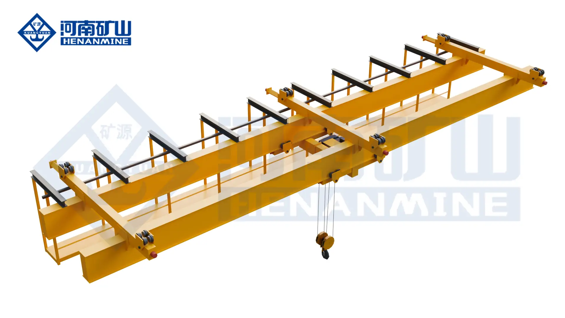
    Henan Mine Crane Single-Girder Bridge Crane
    Henan Mine Crane Single-Girder Bridge Crane
    Project planning notes

    Key points for this crane project.

    1. Overhead Cranes for Industrial Handling
    2. Overhead Crane Technical Specifications
    3. Selection Considerations
    Read the technical guide

    Overhead Cranes for Industrial Handling

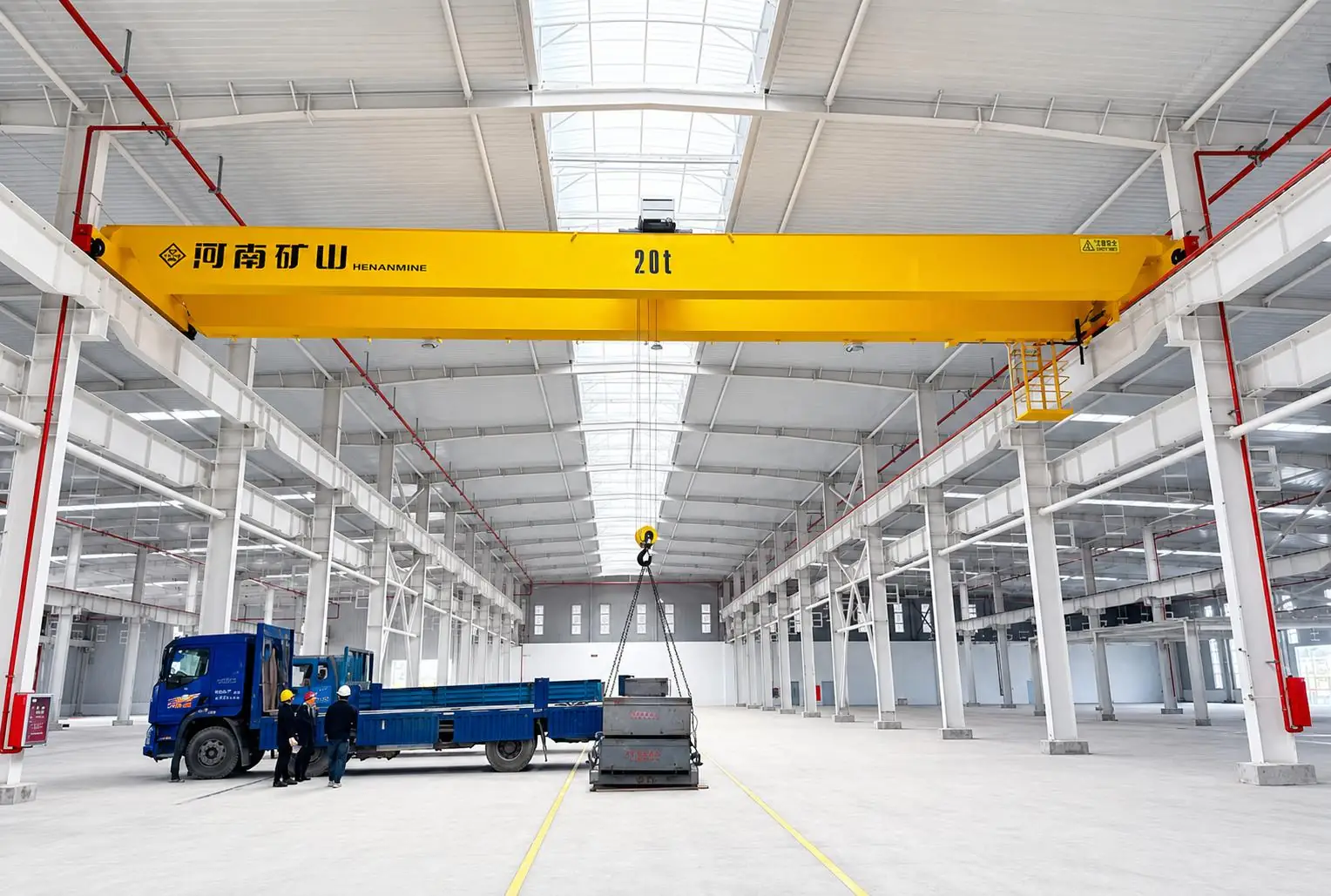
    An overhead bridge crane uses a travelling bridge and hoist or trolley to lift and transfer loads within a defined working bay. It can serve fabrication stations, assembly positions, storage areas and maintenance locations without a floor-mounted travelling crane occupying the same route.

    The appropriate overhead crane for sale depends on what the load must do after it leaves the floor. A maintenance lift, repeated production transfer and controlled placement of an assembly may require different mechanisms, speeds and duties at the same rated capacity.

    Manufacturing and Assembly

    Define the stations to be served, component dimensions and required placement control. Account for machinery and services along the load route.

    Warehousing and Material Transfer

    Check access to storage positions and loading areas. Hook approaches, load length and aisle arrangements determine the usable coverage.

    Maintenance and Equipment Handling

    Specify the heaviest assembly and the lifting height needed to clear equipment. Allow space for lifting beams, slings and component removal.

    Overhead Crane Technical Specifications

    A useful overhead crane quotation identifies the selected values below. Capacity, span and lifting height should be confirmed together with the duty and building layout; a broad catalogue range is not a project specification.

    SpecificationInformation Used to Configure the Crane
    Rated capacityMaximum payload, lifting accessories, load dimensions and centre of gravity; state whether capacity is in metric tonnes or another unit.
    Span and runwayRunway centreline spacing, travel length, rail or beam details, and existing or proposed supports.
    Hook height and coverageHighest and lowest required hook levels, side and end approaches, roof clearance and obstructions.
    Operating dutyLifts per hour, operating shifts, travel distances and the share of lifts near rated load.
    Lifting arrangementElectric hoist or winch trolley, single or multiple hooks, and any dedicated load-handling attachment.
    Motion and controlsHoisting, trolley and bridge travel speeds; pendant, radio remote, cabin or specified automation.
    Site environmentIndoor or outdoor use, temperature, humidity, dust, corrosion, heat and hazardous-area requirements.
    Electrical supplySite voltage, frequency, phases, earthing and the incoming power connection.

    The weight of suspended lifting accessories must be considered when confirming the required crane capacity.

    Selection Considerations

    Start with the Lift

    List the heaviest load and normal operating loads. Show the pickup and placement points and identify any rotation, coordinated lifting or special attachment.

    Check the Building Interface

    Provide a plan and cross-section. For an existing runway, check the proposed wheel loads, wheel spacing, rail interface and clearances against the supporting structure.

    Define the Work Cycle

    Compare cranes at the duty actually required. Frequent production handling can change the hoist, drives, brakes and maintenance requirements even when capacity is unchanged.

    Agree the Complete Scope

    Identify who supplies runway beams, rails, power distribution, supports and installation. Ask for inclusions and exclusions to be listed with the equipment quotation.

    Overhead Crane Configurations Compared

    Compare overhead cranes for sale against the same load, operating cycle and building drawing. Several arrangements may be feasible; the decision should include equipment cost, support requirements and access for maintenance.

    Crane ConfigurationDesign ArrangementWhere to Consider ItQuotation Check
    Single-Girder Overhead CraneOne bridge girder with the selected travelling hoist.Consider for general workshop lifting where the proposed capacity, duty and hook coverage meet the task.Check hoist headroom, hook approaches and runway reactions.
    Double-Girder Overhead CraneTwo bridge girders with the specified trolley or hoist arrangement.Consider when the required lifting envelope, trolley layout or equipment arrangement favours two girders.Compare overall dimensions and mechanism duty; girder count alone does not establish performance.
    Underhung Overhead CraneThe bridge travels on the lower flanges of suitable runway beams.Consider where a suspended runway layout fits an engineered supporting structure.Check beam flanges, supports, connections and clearances.
    Double-Trolley Overhead CraneTwo lifting units on one bridge.Consider for defined two-point handling or independent lifting duties.Specify each hoist rating, permitted combined load and coordinated operating modes.
    Grab Overhead CraneA lifting system configured around a bulk-material grab.Consider for repeated pickup and discharge of suitable bulk materials.Confirm material density, grab self-weight, discharge geometry and required throughput.
    Explosion-Proof Overhead CraneEquipment configured for a specified hazardous environment.Consider where the site classification requires explosion-protected equipment.Match the design and documentation to the actual gas or dust hazard and applicable requirements.

    Single and double girder describe the bridge structure. Top-running and underhung describe how the bridge runs on its runway. These terms cover different design choices and should both be stated where relevant.

    How the Lifting System Affects the Specification

    Hoist and Trolley Arrangement

    The hoist raises the load and the trolley moves it across the bridge. Hook block dimensions, hoist position and trolley limits affect the actual working envelope. Match the lifting mechanism to the load spectrum and lift height.

    Bridge and Runway Interface

    Bridge travel covers the length of the bay. Wheel arrangement, runway geometry and support reactions affect the building interface, so the crane and runway should be evaluated together.

    Speed and Positioning

    Hoisting speed, cross travel and long travel serve different parts of the cycle. Specify any need for slow placement, controlled acceleration or positioning functions so the proposed controls can be assessed.

    Safety and Control Configuration

    Define safety functions and operating modes with the selected crane. The quotation should identify required protections and separately describe additional control or monitoring functions.

    • Load and motion protection: agree overload protection, hoisting and travel limits, brakes, emergency stops and relevant electrical protections, with acceptance checks for the specified functions.
    • Control stations: choose pendant, radio remote or cabin operation around visibility and access. Define control priority and the required response to loss of a command signal.
    • Shared operating areas: assess collision prevention, access controls and operating separation where cranes or equipment share the working bay.
    • Process-specific lifting: magnetic lifting, metallurgical handling and coordinated hoist arrangements require their own load-retention, thermal or fault-response review.

    A crane’s girder arrangement does not define its safety package. Any additional brakes, power-loss provisions, anti-sway controls or monitoring functions must be included explicitly in the agreed design.

    What Should an Overhead Crane Quotation Include?

    An overhead crane price is meaningful only when its scope is clear. Two quotations for the same capacity may cover different equipment, runway interfaces, testing or site work. Request a line-by-line scope before comparing the totals.

    Quotation LineScope to Agree
    Crane equipmentBridge girders, end carriages, hoist or trolley, hook arrangement, drives and crane-mounted electrical equipment.
    Runway equipmentRunway beams, rails or suspended tracks, connections, stops and supporting steelwork, where included.
    Power supplyCrane and runway power distribution, cable arrangements and the boundary with the site incoming supply.
    Inspection and documentationApproved drawings, manuals, electrical diagrams, inspection records and the agreed factory and site test scope.
    Delivery and site workPacking, transport, unloading, installation equipment, labour, commissioning and operator familiarisation, as contracted.

    Ask the overhead crane supplier to list exclusions, site responsibilities, currency, delivery terms and quotation validity. Warranty coverage, spare parts and service arrangements should be stated in the offer.

    What Affects Overhead Crane Price?

    Capacity and span influence the structure, while duty, lift height and operating speeds influence the lifting and travel mechanisms. Restricted headroom, multiple hoists, dedicated attachments, environmental protection and automation can change the configuration further.

    A lower equipment price may cover a different hoist, operating duty or supply boundary. Compare the proposed specification and installed project scope, including any runway work and acceptance requirements.

    Work Cycle and Controls

    Operating duty, speed control, attachment and process functions.

    Manufacturing Review and Order Approval

    Review the Henan Mine Crane manufacturing facilities alongside the product proposal. For your order, agree the records and inspections needed to verify the selected configuration.

    • Approve the general arrangement, hook coverage and building interfaces before manufacture.
    • Confirm component specifications, electrical requirements and any agreed substitutions.
    • Define inspection points, witness arrangements and the required test records.
    • Agree which checks occur at the factory and which require the installed crane on site.

    Applicable standards and conformity documents should be identified for the destination and project. The required records must relate to the supplied crane and its agreed scope.

    Delivery, Installation and After-Sales Support

    Delivery Planning

    Request a schedule tied to drawing approval, component procurement, manufacture, inspection and shipment. Transport time and site readiness should be considered separately from factory completion.

    Installation Readiness

    Confirm runway completion, assembly space, unloading arrangements, power availability and access for installation equipment. Assign responsibility for local lifting equipment and site coordination.

    Service and Spare Parts

    Agree documentation language, operator familiarisation, warranty terms and service scope. Identify maintenance access and recommended spares for the selected hoist, drives, wheels and electrical equipment.

    Overhead Crane Purchase FAQ

    Are these new overhead cranes or used cranes?

    This page covers new overhead cranes manufactured for project requirements. State the required configuration and site conditions when requesting a quotation.

    Are overhead cranes available for immediate delivery?

    Ask about availability for the exact specification. Capacity alone is not enough to establish a match: span, lifting height, duty, power supply and controls must also suit the project. Confirm the delivery date in the offer.

    How much does an overhead crane cost?

    A project quotation is needed because the structure, mechanisms and supply scope vary. Provide capacity, span, lift, duty, building information and site location so the equipment and delivery requirements can be priced together.

    Does the price include runway beams and installation?

    Only if these items are included in the agreed offer. Ask for runway equipment, supporting steelwork, power distribution, installation, commissioning and transport to be listed separately or clearly included.

    Can I buy a crane for an existing workshop?

    Yes, a proposal can be developed for an existing building. Suitability depends on the runway and support assessment, available clearances, hook coverage and electrical supply.

    Can I order a 5 ton or 10 ton overhead crane?

    Include the required capacity in your enquiry together with the load, duty and building dimensions. The selected structure, lifting mechanism and site interfaces must be confirmed for that requirement.

    What should be agreed before placing an order?

    Confirm the technical specification, drawings, inclusions and exclusions, inspection plan, delivery schedule, commercial terms and site responsibilities. Resolve any differences between the enquiry and quotation before acceptance.

    Related Crane Products

    Explosion-Proof Overhead Crane

    Review a configuration for a specified hazardous area.

    5 Ton Overhead Crane

    Compare configurations for a metric 5-ton lifting requirement.

    Send Henan Mine Crane your overhead lifting requirement for configuration and quotation review. A building plan, cross-section and load description help define a proposal that matches the site.

    • Required capacity, typical load and lifting attachment
    • Runway span and length, required lifting height and building clearances
    • Operating cycle, environment, power supply and preferred controls
    • Project country, delivery needs, inspection requirements and installation scope

    Discuss the crane arrangement for your project.

    An equipment enquiry is more useful when it describes a particular lifting job. Provide the load, workshop geometry and duty, then ask suppliers to make the scope and assumptions of their offers explicit. Share the load, available drawings, working cycle and site conditions with Henan Mine Crane so the required configuration and supply boundary can be discussed.

    Related crane configurations

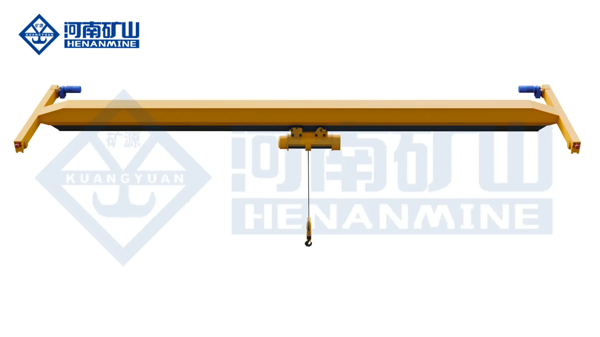
    Single-Girder Bridge Crane

    View product parameters
    Lifting capacity: 1–20 tSpan: 7.5–31.5 mLifting height: 6, 9, 12, 18, 24 or 30 m; capacity-dependent

    Use an LDA single-girder bridge and electric hoist for general workshop material handling. Select the lifting capacity, runway geometry and hoist duty around the building and load.

    LH Electric Hoist Double Girder Crane

    View product parameters
    Lifting capacity: 3, 5, 10, 16, 20 tSpan: 10.5–31.5 mLifting height: 6, 9, 12 or 18 m

    Use an LH double-girder bridge with an electric-hoist trolley for workshop lifting, assembly and maintenance. Match the hoist arrangement to the suspended load, hook travel and available building space.

    Updated 2026 · Henan Mine Crane
  • Forging Cranes: Workpiece Handling and Process Coordination

    Forging Cranes: Workpiece Handling and Process Coordination

    Selection guide

    Forging Cranes: Workpiece Handling and Process Coordination

    Forging operations require the lifting arrangement to follow the workpiece and production sequence. Provide the load condition, attachment requirements and transfer tasks so crane movements and process interfaces can be reviewed together.

    Henan Mine CraneSelection guide · Updated 2026Crane selection, project scope and operating requirements
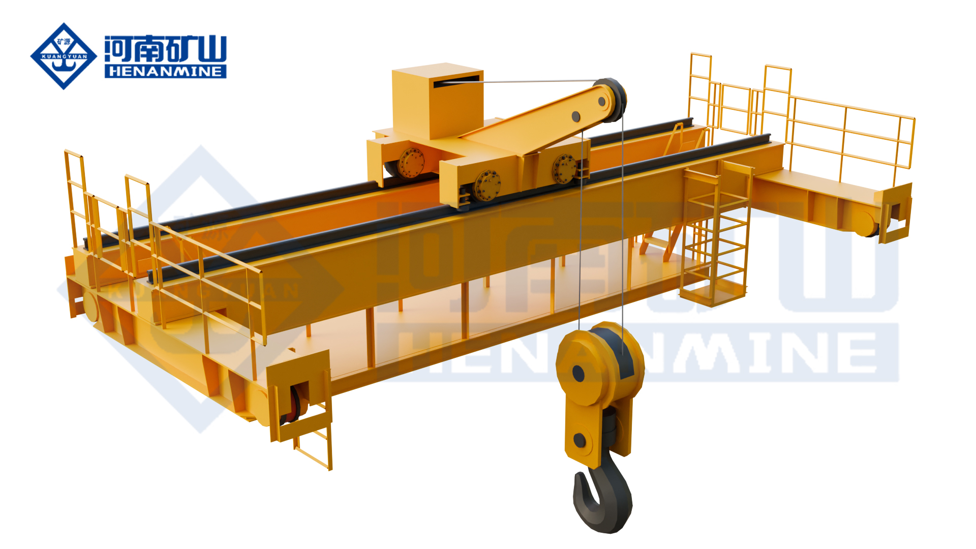
    Henan Mine Crane Galvanizing Process Overhead Crane
    Henan Mine Crane Galvanizing Process Overhead Crane
    Project planning notes

    Key points for this crane project.

    1. What Is a Forging Crane?
    2. Forging Crane Applications
    3. Components and Operating Principle
    Read the technical guide

    What Is a Forging Crane?

    A forging crane, also called a forge-shop crane or forging overhead crane, is a process crane built for the thermal, mechanical and production demands of a forging facility. It moves hot or cold stock between furnaces, presses, hammers, manipulators, inspection stations, heat-treatment equipment and storage positions. A specialized system can also rotate or reposition a workpiece during the forging sequence.

    The term covers two substantially different duties. A forge-shop handling crane transfers ingots, dies, tooling and finished forgings between stations. A press-coordinated forging crane participates directly in open-die forging by supporting and turning a heavy workpiece in coordination with the press or manipulator. The second duty normally requires higher working intensity, controlled load buffering, purpose-designed turning equipment and a control philosophy matched to the production sequence.

    A forging crane is not automatically a foundry crane. Foundry or casting cranes are designed for ladles and molten metal; quenching cranes are designed for rapid immersion into a treatment bath. Either may be required elsewhere in the same plant, but each process must be specified separately. Henan Mine Crane develops the forging system from the declared solid-workpiece duty and integrates relevant features from its metallurgical bridge crane and double-girder bridge crane platforms.

    Forging Crane Applications

    Open-Die Forging Press

    Support, rotate and reposition large ingots or forgings through repeated press strokes using approved hooks, tongs or a powered turning device.

    Forging Hammer Bay

    Transfer heated stock, dies and tooling while accounting for shock, vibration, scale and restricted approach around the hammer foundation.

    Furnace Charging and Extraction

    Move ingots or billets to and from heating furnaces with attachment clearance, radiant-heat protection and a controlled pickup orientation.

    Die and Tool Handling

    Change upper and lower dies, anvils, saddles and press tooling with the hook approach, creep speed and maintenance access required by the equipment layout.

    Heat Treatment and Cooling

    Transfer forged parts to normalizing, annealing, cooling or inspection positions; rapid immersion requires a separately defined quenching-crane function.

    Machining and Dispatch

    Move cooled forgings between cleaning, inspection, machining, weighing, storage and shipment when one crane serves the downstream production route.

    Components and Operating Principle

    1. Bridge and end carriages: carry the process trolley and distribute vertical, transverse and longitudinal reactions to the runway.
    2. Main hoist: supports the maximum forging, ingot, die or suspended turning assembly and provides controlled lifting under the declared duty.
    3. Auxiliary hoist: supports turning, tailing, tool handling or secondary positioning when the approved operation requires two lifting points.
    4. Below-hook device: may be a hook rig, tong, clamp, spreader, chain-turning assembly or powered turning unit designed for the workpiece.
    5. Drives and controls: coordinate hoisting, trolley travel, bridge travel, creep speeds, interlocks, monitoring and optional press-line communication.
    6. Thermal and environmental protection: shields structures, ropes, cables, motors, brakes, panels, sensors and the operator station from the declared exposure.

    Rated-load basis: the crane rating starts with the maximum gross suspended load. This includes the heaviest workpiece, tongs or turning device, spreader, rigging, hook blocks and every other suspended component. The forging mass alone is not the required crane capacity.

    Forging Crane Selection Considerations

    Selection begins with the forging sequence and complete load spectrum. Nominal tonnage alone cannot define the structure, mechanisms, attachment or safety architecture.

    Load Matrix

    Minimum, typical and maximum mass; workpiece dimensions; center-of-gravity range; dies and tooling; attachment mass; single- or dual-point lifting; off-center cases.

    Forging Sequence

    Furnace pickup, press or hammer approach, rotation angle, number of turns, hold time, transfer path, handover to manipulator and downstream placement.

    Temperature and Environment

    Workpiece and furnace temperatures, radiant-heat intensity and duration, ambient range, scale, dust, smoke, oil mist, water spray, vibration and corrosive exposure.

    Duty and Dynamics

    Cycles per hour, starts and reversals, shifts, annual hours, load spectrum, press interaction, permitted shock, required buffering and production consequence of downtime.

    Building and Equipment Interface

    Rail-center span, runway length and elevation, wheel-load limits, headroom, hook approaches, press columns, furnace doors, manipulator envelope and maintenance access.

    Control and Acceptance

    Cabin or radio control, visibility, cameras, creep speed, positioning tolerance, press/MES signals, fallback modes, proof load, representative-workpiece test and documentation.

    Forging Crane Configurations Compared

    The configuration follows the actual process function. Equipment from adjacent metallurgical duties should not be substituted without a complete engineering review.

    ConfigurationSuitable DutyTypical Load HandlingEngineering Focus
    Heavy-duty hook forging craneIngot, die, tooling and forged-part transferMain hook with approved rigging or spreaderDuty, creep speed, heat protection, hook approach and maintenance access
    Main-and-auxiliary hook forging craneTransfer, tailing and planned load rotationTwo hooks with approved turning rig or attachmentHook spacing, capacity split, synchronized control, rope fleet angles and permitted load cases
    Tong or clamp forging craneRepeated pickup of defined ingots, billets or forgingsMechanical, hydraulic or powered gripping attachmentGrip range, surface contact, hot strength, fail-safe state, scale and attachment mass
    Press-coordinated forging craneDirect participation in heavy open-die forgingMain hoist plus turning device, tongs or manipulator interfaceLoad buffering, impact limits, rapid reversals, positioning, communication and production availability
    Quenching craneRapid, controlled immersion of hot workpiecesHook, fixture or basket matched to the bathFast lowering/lifting, emergency recovery, bath geometry, vapor and splash exposure
    Foundry or casting craneLadle handling and molten-metal transferGantry hook or ladle lifting attachmentMolten-metal-specific redundancy, thermal protection and regulatory requirements

    Preliminary Forging Crane Specification Framework

    The values below identify the decisions required for a technical proposal. Final parameters are established after the load cases, process sequence and workshop interfaces are approved.

    ParameterProject DefinitionRequired Input
    Rated lifting capacitySelected from maximum gross suspended load and governing load casesWorkpiece, attachment, rigging, hook block and off-center loads
    Main / auxiliary capacitySingle hoist, main plus auxiliary, or coordinated multi-hoist arrangementTurning method, capacity split and simultaneous-use cases
    Structure and trolleyDouble-girder process crane; special multi-girder or dual-trolley layout where justifiedCapacity, span, wheel loads, headroom, rigidity and access
    Span and lifting heightEngineered from rail centers, hook travel and process clearanceWorkshop section, press/furnace drawings and runway survey
    Working dutyCalculated under the selected classification systemLoad spectrum, cycles, starts, shifts, annual hours and process dynamics
    Hoisting and travel speedsProcess, transfer and creep speeds with variable-frequency control as requiredCycle time, positioning tolerance, travel distance and load stability
    Thermal designHeat shields, protected components, cooling or relocated equipmentWorkpiece temperature, radiant flux or distance/time profile and ambient range
    Control systemCabin, radio, local station, semi-automatic or integrated automatic controlVisibility, operator location, interfaces, fallback mode and safety zones

    Smaller forge-shop handling cranes and larger custom systems also exist. These are market reference ranges, not fixed Henan Mine Crane catalog limits or a substitute for project calculations.

    Hot-Workpiece Handling and Turning Engineering

    Turning a forging creates load cases that may be more demanding than a straight vertical lift. The center of gravity moves, sling or chain angles change, one hook can temporarily carry a larger share, and the workpiece may contact a saddle, manipulator or die. The approved method must define the load path through every stage.

    Main + Auxiliary Hooks

    Define simultaneous-use capacity, hook spacing, permitted angles, speed coordination and the maximum reaction on either hoist.

    Powered Turning Device

    Specify torque, workpiece range, rotation speed, restraint, heat protection, emergency state and attachment-to-crane interface.

    Tongs and Clamps

    Validate grip range, hot material behavior, contact pressure, surface scale, loss-of-power condition and visual confirmation.

    Rigging and Saddles

    Confirm temperature rating, bend radius, edge protection, contact geometry, inspection access and storage away from radiant heat.

    Process control: no operator should have to improvise the turning sequence. The approved lifting plan, control logic, permissible load cases, communication signals and abnormal-condition recovery are established before commissioning and verified with representative loads.

    Heat, Scale, Shock and Environmental Protection

    Thermal Mapping

    Evaluate workpiece temperature, exposure distance, dwell time and radiant paths at the hooks, trolley, girders, cabin, panels and maintenance platforms.

    Protected Hoisting System

    Select ropes, drums, sheaves, bearings, lubrication, brakes and cables for the measured environment and shield them from direct heat and scale.

    Electrical Protection

    Use suitable enclosures, cable routing, cooling or equipment relocation and monitor critical temperatures where the risk assessment requires it.

    Shock and Vibration

    Define permitted process forces, acceleration limits, buffering and structural fatigue cases; the crane must not be used to absorb undefined press or hammer impacts.

    Operator Visibility

    Coordinate cabin position, heat-resistant glazing where specified, cameras, lighting, audio communication and safe radio-control locations.

    Maintainability

    Provide safe access to brakes, ropes, sheaves, drives, panels and attachment points, with guards and shields removable under an isolation procedure.

    Manual, Semi-Automatic and Integrated Forging Operation

    The control level follows process repeatability, visibility, cycle time, exception rate and the production system’s ability to provide dependable interlocks and workpiece data.

    Control LevelTypical FunctionsSuitable Operating PatternDefinition Required
    Manual controlCabin or radio control, variable speeds, load display, cameras and interlocksMixed workpieces, frequent exceptions and operator-led riggingSightlines, control location, communications, exclusion zones and permitted motions
    Semi-automaticStored positions, automatic travel profiles or assisted turning with operator authorizationRepeated stations with controlled workpiece familiesCoordinates, confirmation logic, permissible sequence and exception recovery
    Press-line integratedSignal exchange with press, manipulator, furnace and safety control systemsHigh-repeatability open-die forging and coordinated productionSignal list, ownership, timing, safe states, independent stops and commissioning protocol
    Automatic material flowTask receipt, route control, positioning, status feedback and production-data exchangeControlled transfer between fixed stations with limited human accessPlant interface, zone control, workpiece identity, cybersecurity and manual fallback

    Design Basis, Inspection and Acceptance

    The purchase specification identifies one coherent design route.

    Possible Design Routes

    A project may use ISO 4301 classification principles with applicable crane standards; EN 13001 with EN 15011 and EN 13155 where applicable; or a North American route using CMAA 70 with applicable ASME B30.2, B30.20 and ASME BTH-1 requirements. The contract states the selected basis and local additions.

    Engineering Deliverables

    General arrangement, load-case schedule, duty calculation, wheel loads, clearance and turning study, attachment data, thermal assessment, electrical drawings, control narrative, interface list, inspection plan and maintenance-access arrangement.

    Manufacturing Inspection

    Material traceability, welding procedures and welder qualification, specified NDT, dimensional checks, machinery alignment, drum and rope inspection, attachment inspection, electrical-panel tests, coating and document review.

    FAT and Site Acceptance

    Functional tests verify motions, brakes, limits, overload protection, control modes, alarms and interfaces. Site testing then covers runway, erection, proof load, representative workpieces, turning sequence, power-loss response, positioning, press coordination, training and handover.

    Acceptance ItemVerificationRecorded Evidence
    Rated and governing load casesContractual proof/load test and functional motion checksTest procedure, calibrated instruments and signed results
    Turning and attachmentApproved representative workpieces across the declared envelopeWorkpiece list, sequence, grip/rigging checks and exception record
    Safety and controlsLimits, overload, stops, interlocks, communication loss and fallback modesCause-and-effect record and completed test sheets
    Handover readinessTraining, spares, manuals, inspection plan and maintenance accessHandover dossier, punch-list closure and acceptance certificate

    Relevant Heavy Metallurgical Crane Experience

    Relevant references are evaluated by capacity, thermal exposure, duty, trolley architecture, process control and commissioning complexity. The following published Henan Mine Crane projects demonstrate adjacent engineering capability; a new forging crane still requires its own process and load-case validation.

    360 t Four-Girder Foundry Crane

    The reference is relevant to ultra-heavy structure, trolley coordination and high-temperature engineering. Its molten-metal duty does not define the attachment, motion sequence or safety architecture of a forging crane.

    Hot-Rolled Steel Plant Bridge Cranes

    This experience is relevant to radiant-heat exposure, continuous steel-plant operation and equipment interfaces. Forging impact, turning and attachment requirements remain separate design inputs.

    Reference boundary: adjacent metallurgical projects demonstrate relevant structural, mechanism, thermal-protection and control experience.

    Forging Crane Budget and Supply Scope

    A forging-crane quotation must describe the complete handling process: gross suspended load, hot-workpiece geometry, turning method, lifting frequency and thermal exposure. Include the manipulator, lifting attachment and coordinated movements where they are part of the operation.

    Budget packageScope that needs definition
    Crane and process attachmentLoad cases, girder and trolley arrangement, turning equipment and attachment mass
    Duty and heat protectionOperating cycle, temperature exposure, shielding, component protection and service access
    Controls and interfacesMotion coordination, operating positions, process interfaces and agreed protection functions
    Project deliveryRunways, power supply, freight, erection, commissioning, testing, documents and spare parts

    Send these inputs to Henan Mine Crane for a project-specific technical and commercial proposal. Compare the agreed process scope line by line; a general workshop-crane price does not represent a forging system.

    Forging Crane RFQ Information

    A complete enquiry allows the structure, hoists, turning system, thermal protection, runway reactions, controls and commercial scope to be priced on the same basis.

    Workpiece and Attachment Data

    Minimum, typical and maximum mass and dimensions; temperature at pickup; center of gravity; material and surface; dies and tooling; required tongs, clamp, turner, spreader or rigging; drawings and photographs.

    Process and Duty

    Furnace, press, hammer, manipulator and heat-treatment sequence; lifts and turns per hour; shifts; annual hours; load spectrum; required cycle time; permitted process forces and production consequence of downtime.

    Workshop and Runway

    Rail-center span, runway length, rail and elevation; required lift; headroom and approaches; existing wheel-load limits; press, furnace, platform and duct drawings; installation access and site-survey data.

    Controls and Commercial Scope

    Cabin, radio or automatic control; positioning tolerance; press/MES protocol; voltage and frequency; environment; destination; compliance route; Incoterm; runway, electrification, installation, commissioning, testing and documentation scope.

    Frequently Asked Questions

    How is forging crane capacity calculated?

    Capacity begins with the maximum workpiece and adds tongs, turning device, spreader, rigging, hook blocks and other suspended equipment. The design then evaluates off-center loads, main/auxiliary load sharing, dynamics and the selected duty classification.

    Is a forging crane the same as a foundry crane?

    A forging crane principally handles solid ingots, dies and forgings and may assist rotation at a press. A foundry crane handles ladles and molten metal under a different risk profile and safety architecture.

    When are main and auxiliary hooks required?

    They are considered when the approved process requires tailing, turning, secondary positioning or tool handling. Hook spacing, capacity split, simultaneous loading and the complete rotation sequence must be defined before selection.

    Can a standard overhead crane handle hot forgings?

    Only after a dedicated engineering review. Radiant heat, scale, duty, process dynamics, attachment, visibility and component temperatures can require structural, mechanical, electrical and control measures beyond a general-purpose crane.

    How much does a forging crane cost?

    Final cost depends on the full process, attachment, thermal design, duty, runway, controls and delivery scope.

    Can a forging crane coordinate with a hydraulic press?

    Yes, when the crane, press, manipulator and safety systems share an approved functional specification. The signal matrix defines command ownership, permissives, timing, safe states, independent stops and recovery after a fault.

    Can an existing runway be reused?

    Only after the rails, beams, brackets, columns, connections and foundations are checked for condition, alignment, fatigue and the new crane reactions. Heavy process trolleys and special attachments can change wheel loads materially.

    What should be tested before handover?

    Testing covers motions, brakes, limits, overload protection, control modes, attachment functions, representative workpieces, turning sequences, power-loss response, positioning, interfaces, safety zones and manual recovery under agreed criteria.

    Related Forge-Shop and Metallurgical Crane Products

    Each platform serves a different process risk and load-handling function. Final selection follows the approved material, temperature, sequence, duty and site data.

    Metallurgical Bridge Crane

    Process-duty platform for declared high-temperature and heavy metallurgical applications.

    Double-Girder Bridge Crane

    Configurable bridge platform for general forge-shop transfer, die handling and maintenance lifting.

    Quenching Crane

    Specialized heat-treatment crane for rapid workpiece immersion, recovery and bath transfer.

    Double-Girder Casting Crane

    Molten-metal handling platform for foundry processes where ladle transfer is separately in scope.

    Automatic Metallurgical Crane

    Integrated control reference for defined production routes, positioning and plant-system communication.

    Special Metallurgical Overhead Crane

    Project-specific lifting platform for demanding metallurgical process conditions and safety requirements.

    Submit the workpiece and attachment matrix, temperature, forging sequence, lifts and turns per hour, press, furnace and manipulator drawings, span, lift, runway data, required control level, power supply, destination and supply boundary. Henan Mine Crane will prepare a configuration-based technical and commercial proposal.

    Discuss the crane arrangement for your project.

    Forging operations require the lifting arrangement to follow the workpiece and production sequence. Provide the load condition, attachment requirements and transfer tasks so crane movements and process interfaces can be reviewed together. Share the load, available drawings, working cycle and site conditions with Henan Mine Crane so the required configuration and supply boundary can be discussed.

    Related crane configurations

    Galvanizing Process Overhead Crane

    View product parameters
    Lifting capacity: 5 – 32 tSpan: 10.5 – 31.5 mLifting height: 6 – 24 m

    Transfer suspended workpieces through a galvanizing process with a crane matched to the line. Coordinate lifting points, corrosive exposure, tank geometry and the required handling sequence.

    Updated 2026 · Henan Mine Crane

  • Overhead Bridge Crane Projects: Check the Working Envelope and Runway

    Overhead Bridge Crane Projects: Check the Working Envelope and Runway

    Selection guide

    Overhead Bridge Crane Projects: Check the Working Envelope and Runway

    The bridge crane must fit both the supporting structure and the required hook positions. Describe the load, travel route and operating cycle so the proposal can be assessed against the actual facility.

    Henan Mine CraneSelection guide · Updated 2026Crane selection, project scope and operating requirements
    Henan Mine Crane Single-Girder Bridge Crane
    Henan Mine Crane Single-Girder Bridge Crane
    Project planning notes

    Key points for this crane project.

    1. Overhead Bridge Cranes for Workshops and Warehouses
    2. Overhead Bridge Crane Technical Specifications
    3. Selection Considerations
    Read the technical guide

    Overhead Bridge Cranes for Workshops and Warehouses

    Overhead crane and bridge crane are common names for this arrangement. Electrically powered travelling models are also called EOT cranes. The practical selection starts with the material flow and the space the hook must reach.

    Connect Production Stations

    Transfer components between fabrication, machining and assembly positions within one crane bay. Include the load orientation and lifting attachment required at each station.

    Serve Storage and Loading Areas

    Reach designated storage lanes and loading positions from above. Check obstructions, vehicle access and the available hook approach at the ends of the runway.

    Handle Maintenance Lifts

    Lift equipment clear of its mounting and move it to a service area. Allow enough hook height for the lifting gear and enough horizontal clearance for the complete component.

    The load path remains within the crane’s defined coverage. Supporting columns, runway steelwork, overhead services and maintenance access still need to be accommodated in the facility layout.

    Overhead Bridge Crane Technical Specifications

    The references below correspond to the linked Henan Mine Crane product tables. They help shortlist an arrangement; the final project specification also defines duty, speed, hook approaches and structural reactions.

    All t values here are metric tonnes. If your project uses US short tons, identify that unit in the enquiry. Confirm the complete load, span and lifting-height combination for the selected model; maximum catalogue values are not automatically available together.

    Additional Technical Inputs

    • Maximum and typical cargo weights, load dimensions, centre of gravity and lifting gear.
    • Runway length and elevation, highest and lowest required hook positions, and coverage at each workstation.
    • Lifts per hour, load distribution, operating shifts, travel distances and positioning needs.
    • Supply voltage, frequency and phases; control method; environment and required design standard.
    • Wheel loads, wheel spacing, runway interfaces, access platforms and agreed installation scope.

    Selection Considerations

    Start with the Lifted Load

    Describe the cargo and the slings, lifting beams, grabs or other attachments. Their weights and geometry affect the required rating, hook height and usable payload.

    Map the Working Area

    Mark every pickup and placement point on the building plan. Include machine enclosures, doors, stored goods and services that could restrict the load or hook path.

    Match the Production Duty

    Separate occasional maintenance lifting from repetitive production handling. Load spectrum, operating time and travel distances help determine the crane and mechanism duties.

    Review the Complete Installation

    Compare the crane with its runway, supporting structure, power supply and service access. A lower equipment price can come with a different building or installation requirement.

    Overhead Bridge Crane Compared with Other Industrial Crane Configurations

    Girder count and runway arrangement are separate choices. A single-girder crane can have a top-running bridge with an under-running hoist; the position of that hoist does not classify the bridge as underhung.

    ConfigurationStructural ArrangementSelection Trade-Off
    Single-Girder Overhead Bridge CraneOne main girder, commonly with a travelling hoist below the beam.A compact arrangement for general handling. Compare hook height, side approaches, duty and total installed cost.
    Double-Girder Overhead Bridge CraneTwo main girders carrying the selected trolley and lifting mechanism.Allows different trolley and hook arrangements. Review crane height, runway loading and maintenance access for the proposed layout.
    Underhung Overhead Bridge CraneThe bridge travels on the lower flanges of suitable elevated runway beams.Useful where the building supports a suspended runway layout. Flange loading, connections and supporting steelwork require assessment.
    Multi-Support Underhung Bridge CraneA suspended bridge uses multiple runway supports across the working area.Consider for an engineered multi-rail facility. Coordinate support locations, alignment and the distribution of loads.
    Gantry CraneLegs carry the bridge above ground-level runways or a specified travel system.An alternative where elevated runways are unsuitable. Account for leg clearance, travel lanes, ground conditions and foundations.

    For a top-running overhead bridge crane, the end carriages run on rails above the runway beams. Those runways may be carried by building columns or by an independent engineered support structure.

    Hook Coverage, Headroom and Load Clearance

    Span Is Not Hook Coverage

    Span is based on the runway centreline spacing. Side and end approaches, together with any engineered overhang, determine where the hook can travel. Check the resulting working area against the layout.

    Lifting Height Is Not Building Height

    Determine the required highest hook position from the load, lifting gear and obstacle clearance. Then check the complete crane envelope against roof members, lighting, ductwork and maintenance space.

    The Load Needs Clearance Too

    A reachable hook position does not guarantee that a long beam or bulky machine can pass through the same area. Check the suspended load’s dimensions and intended orientation along the full route.

    For restricted headroom, compare a low-headroom hoist and alternative bridge layouts on the same building cross-section. The useful result is the achievable hook level with the required clearances and access.

    Runway Loads and Building Support

    Runway selection is part of the crane installation. Crane deadweight, trolley position, lifted load and the agreed design load combinations influence the forces transferred to the building or independent supports.

    New Building

    Coordinate the crane drawing with the structural design before fixing runway elevations and column positions. Include power routes, end clearances and access to the lifting and travel equipment.

    Existing Building

    Survey the rails, runway beams, connections and supporting structure. Use the proposed wheel loads, wheel spacing and horizontal reactions for the structural review.

    Replacement Crane

    Compare the actual interfaces of the old and proposed cranes. The same rated capacity can come with different crane weight, wheelbase, loading, hook approaches and electrical demand.

    Define who supplies the runway beams, rails, columns, brackets and foundations. The crane quotation and the building design should use the same approved installation data.

    Hoists, Trolleys and Operating Duty

    Choose the lifting mechanism around the load and work cycle. A double-girder structure does not by itself establish heavy-duty or continuous-service capability; both the crane and its individual mechanisms need suitable classifications.

    Hoist or Trolley Arrangement

    Compare the selected hoist layout, lifting height, hook block, maintenance access and available speeds. The arrangement also affects the hook approaches and structural loads.

    Main, Auxiliary or Dual Hoists

    Identify the task for each hook and any permitted combined operation. Ratings, hook separation, shared loads and control coordination must be defined for multi-hook handling.

    Operating Cycle

    Record the frequency of near-rated lifts, mechanism running time, starts and travel distances. These inputs help distinguish intermittent workshop use from repetitive production service.

    For long components, review the double-trolley electric-hoist bridge crane arrangement. For controlled speed and acceleration, compare the frequency-conversion electric-hoist overhead crane. Specify the required performance for each motion.

    Controls, Power Supply and Motion Performance

    Pendant, Radio or Cabin Control

    Select around operator visibility, travel routes and the handling task. Multiple control stations require a defined selection priority and response to a loss of command signal.

    Power Feed and Distribution

    Confirm site voltage, frequency, phases and the connection point. Distinguish the runway power system from the cable or conductor arrangement supplying the moving hoist or trolley.

    Speed and Positioning

    Specify hoisting, trolley travel and bridge travel separately. Include acceleration, stopping and placement needs; maximum travel speed alone does not define the handling cycle.

    Anti-sway, automatic positioning, load monitoring and production interfaces are functions to specify individually. Agree their operating conditions and acceptance method before they become part of the supply scope.

    Attachments, Special Environments and Safety

    A general workshop hook crane is only one configuration. The material and environment can change the lifting attachment, mechanical design, controls and protection requirements:

    • Grab overhead cranes handle suitable bulk materials. Supply material density, condition, required throughput and discharge height so grab payload and crane duty can be selected together.
    • Explosion-proof overhead cranes require the site’s hazardous-area classification and relevant gas or dust information. Equipment protection and documentation must match that application.
    • Metallurgical bridge cranes address defined hot-material and production duties. Describe the process, temperature exposure and consequences of a lifting interruption.
    • Outdoor or corrosive locations require review of weather exposure, coatings, electrical protection, runway conditions and relevant wind requirements.

    Protection and Safety Functions

    Define overload protection, hoisting and travel limits, braking, emergency stops and electrical protections for the selected crane. Shared runways need an assessment of crane separation and collision prevention. Additional brakes, monitoring or redundancy arrangements depend on the intended duty and risk assessment.

    Manufacturing and Inspection Documentation

    Henan Mine Crane manufactures overhead lifting equipment for industrial production and material handling. View the company’s manufacturing workshops for published factory photographs.

    The order documentation should connect the selected crane configuration with the equipment supplied. Agree the following requirements before manufacture:

    • General arrangement drawing showing rated capacity, span, hook limits, crane dimensions and runway interfaces.
    • Hoist, motor, drive and control schedule with electrical diagrams and protection functions.
    • Material and fabrication inspection scope, including specified weld examination and dimensional checks.
    • Factory and site test requirements, acceptance records, manuals and a parts list.

    Define witness points and the records needed at handover. Any required conformity documentation must apply to the ordered equipment and its destination.

    Installation, Commissioning and Maintenance

    Prepare the Installation

    Coordinate delivery with runway readiness, power availability, assembly space and access for lifting equipment. Identify the party responsible for unloading, erection and electrical connections.

    Agree Acceptance

    Define alignment checks, functional tests, protection checks and the applicable load-test scope. Allocate responsibility for test loads, witnessing, records and operator familiarisation.

    Plan Maintenance Access

    Provide safe access and isolation arrangements for hoists, ropes, brakes, wheels and electrical equipment. Follow the supplied manuals and actual duty when setting inspection and lubrication intervals.

    For a production-critical crane, identify essential spares and the space needed to remove components before operation begins. Maintenance access can affect the building layout as well as the crane arrangement.

    Overhead Bridge Crane Price and Supply Scope

    An overhead bridge crane price reflects the load, span, lift, duty, hoist arrangement, controls and supply boundaries. Compare quotations for the same working envelope and operating requirement.

    • Crane equipment: bridge, end carriages, hoist or trolley, controls and agreed protection functions.
    • Runway and power: beams, rails, support steelwork and electrical distribution, as specified.
    • Project services: packing, transport, unloading, installation, commissioning and training scope.
    • Handover requirements: inspection records, manuals, spares, delivery terms and service arrangements.

    When comparing an overhead bridge crane for sale with a hoist or crane kit, check exactly which structures and services are included. Request the selected configuration, exclusions and delivery schedule in the project quotation.

    Overhead Bridge Crane FAQ

    What is the difference between an overhead crane, bridge crane and EOT crane?

    Overhead crane and bridge crane commonly refer to the same moving-bridge arrangement. EOT means electric overhead travelling and identifies an electrically powered design. The selected bridge, hoist and runway arrangement still need to be specified.

    Should I choose a single-girder or double-girder overhead bridge crane?

    Compare the load, span, highest hook position, duty, runway reactions and installed cost. Double-girder designs allow different trolley arrangements, while a single-girder system may suit general handling. The project layout determines the practical choice.

    Are top-running and underhung cranes different from single- and double-girder cranes?

    Top running and underhung describe how the bridge travels on its runways. Single and double girder describe the bridge beams. An under-running hoist can be used on a top-running single-girder bridge.

    Can an overhead bridge crane use an existing building?

    It may be possible after the structure and runway are assessed for the proposed crane. Provide building drawings, runway details and condition information. An existing crane’s lifting capacity alone is insufficient to establish compatibility.

    Can the hook reach every part of the crane bay?

    Coverage is limited by side and end approaches, hook height and obstructions. Show each required lifting position on the plan and check both the hook and the suspended load against the proposed crane dimensions.

    Do you offer 5-ton and 10-ton overhead bridge crane configurations?

    Final span, lift, duty and building interfaces need confirmation.

    What information is needed for an overhead bridge crane quotation?

    Send the required capacity and unit, span, lifting height, runway length, working cycle and power supply. Include load details, the installation country, a building drawing and the required equipment and service scope.

    Related Crane Products

    Single-Girder Bridge Crane

    Electric-hoist configurations for workshop, assembly and maintenance lifting.

    Double-Girder Electric-Hoist Crane

    Two bridge girders supporting a hoist trolley for a defined lifting envelope.

    Multi-Support Underhung Crane

    Suspended bridge coverage across an engineered multi-runway structure.

    Double-Trolley Overhead Crane

    Two lifting points with defined independent or coordinated operation.

    Frequency-Conversion Overhead Crane

    Electric-hoist arrangements with specified speed control and optional monitoring.

    Explosion-Proof Overhead Crane

    Crane configurations selected for a defined hazardous area.

    Send Henan Mine Crane your load requirement, span, lifting height and operating cycle. Add the building layout, site power supply, installation country and required supply scope so the proposal can address the crane, its working area and its installation interfaces.

    Discuss the crane arrangement for your project.

    The bridge crane must fit both the supporting structure and the required hook positions. Describe the load, travel route and operating cycle so the proposal can be assessed against the actual facility. Share the load, available drawings, working cycle and site conditions with Henan Mine Crane so the required configuration and supply boundary can be discussed.

    Related crane configurations

    Single-Girder Bridge Crane

    View product parameters
    Lifting capacity: 1–20 tSpan: 7.5–31.5 mLifting height: 6, 9, 12, 18, 24 or 30 m; capacity-dependent

    Use an LDA single-girder bridge and electric hoist for general workshop material handling. Select the lifting capacity, runway geometry and hoist duty around the building and load.

    LH Electric Hoist Double Girder Crane

    View product parameters
    Lifting capacity: 3, 5, 10, 16, 20 tSpan: 10.5–31.5 mLifting height: 6, 9, 12 or 18 m

    Use an LH double-girder bridge with an electric-hoist trolley for workshop lifting, assembly and maintenance. Match the hoist arrangement to the suspended load, hook travel and available building space.

    Updated 2026 · Henan Mine Crane

  • 600 t Overhead Crane Built for a Pumped-Storage Power Station

    600 t Overhead Crane Built for a Pumped-Storage Power Station

    Project Deliveries

    600 t Overhead Crane Built for a Pumped-Storage Power Station

    Henan Mine Crane manufactured a package of cranes for a pumped-storage power station project. It includes a 600 t overhead crane with synchronized dual-hook operation, anti-sway functions and digital monitoring.

    600 t dual-hook overhead crane shown at Henan Mine Crane factory for a pumped-storage project
    A 600 t overhead crane photographed during factory-stage work for a pumped-storage power station package.

    Crane package for heavy power-station lifts

    The station equipment package includes multiple crane types. Its specified heavy-lift unit is a 600 t overhead crane using high-strength steel and major components from international brands. The project photo shows the crane at Henan Mine Crane’s factory.

    Power-station crane selection must align the heaviest generator or turbine component with the building envelope and each lifting stage. Confirm capacity at the complete suspended load, hook coverage, available headroom and maintenance access before finalising the bridge and trolley arrangement.

    Dual-hook coordination and monitoring

    The 600 t crane combines high-precision synchronization between its two hooks, intelligent anti-sway and digital monitoring. For large turbine or generator components, define permitted load share, hook spacing, synchronisation mode, control interlocks and a step-by-step lifting procedure in the project specification. Set measurable acceptance criteria for positioning and safety functions during technical review.

    Define your pumped-storage lifting scope

    Provide the maximum assembled and service-component weights, lift points, centre of gravity, rigging weight and required lifting route. Add powerhouse sections, runway elevation and rail gauge, headroom, hook approaches, maintenance clearance, operating frequency, power supply and applicable site standards. Ask for a project-specific general arrangement, load-combination review, functional description, inspection and testing plan, and a clear boundary for installation and commissioning.

    Discuss a Pumped-Storage Crane Package

    Send your unit weights, powerhouse layout, hook travel and handling sequence to define the crane configuration and supply scope.

  • Aircraft Hangar Crane Systems: Maintenance Coverage and Coordination

    Aircraft Hangar Crane Systems: Maintenance Coverage and Coordination

    Selection guide

    Aircraft Hangar Crane Systems: Maintenance Coverage and Coordination

    Hangar lifting should be based on the aircraft tasks and approved handling positions. Show the building envelope, obstacles and required coordination so the crane system can be developed around the maintenance operation.

    Henan Mine CraneSelection guide · Updated 2026Crane selection, project scope and operating requirements
    Henan Mine Crane Multi Support Double Girder Underhung Crane
    Henan Mine Crane Multi Support Double Girder Underhung Crane
    Project planning notes

    Key points for this crane project.

    1. Build the crane brief from maintenance tasks
    2. Explain which movements need coordination
    3. Coordinate the crane with other hangar systems
    Read the technical guide

    Build the crane brief from maintenance tasks

    List the aircraft maintenance operations that need lifting support. Identify the component, approved handling method, required service position and equipment used at each stage. Keep the aircraft maintenance organisation responsible for its approved procedures and lifting points.

    A general hangar coverage drawing is only one part of the brief. The system also needs to support the sequence of work, access around the aircraft and the way components are moved between workstations.

    Explain which movements need coordination

    Some maintenance operations use more than one lifting point or involve a long component. Describe the intended operation and the required relationship between hooks without assuming that independent rated capacities establish an acceptable combined lift.

    Ask for the proposed control arrangement, operating limits and fault response where coordinated movement is required. The engineering review should identify who owns the lifting attachment, who defines the procedure and how the crane system is accepted for the agreed task.

    Coordinate the crane with other hangar systems

    Show maintenance platforms, docking equipment, doors, services and storage positions alongside the aircraft envelope. Describe which of those systems moves during the maintenance sequence and which must remain clear while lifting takes place.

    Where several cranes or trolleys share the working area, define operating zones and control priority. Identify interfaces that need a signal or an operating procedure rather than leaving coordination to an assumption made after installation.

    Plan operator visibility and maintenance availability

    Choose control locations around the actual work positions and the visibility of the suspended component. Discuss how commands are selected and how an interrupted command is handled. Include the people and equipment occupying the maintenance area in the operating review.

    Provide access for inspection and component replacement above the hangar floor. State planned maintenance windows and restrictions on setting equipment down near aircraft or service platforms.

    Agree a task-based acceptance demonstration

    The acceptance plan should connect the agreed functions with representative positions and movements. Record which checks demonstrate crane performance and which depend on aircraft-specific tooling or the maintenance organisation’s procedures.

    For a proposal from Henan Mine Crane, provide the task matrix, building drawings and coordination requirements together. This supports an equipment discussion grounded in the maintenance operation rather than a generic hangar crane description.

    Discuss the crane arrangement for your project.

    Hangar lifting should be based on the aircraft tasks and approved handling positions. Show the building envelope, obstacles and required coordination so the crane system can be developed around the maintenance operation. Share the load, available drawings, working cycle and site conditions with Henan Mine Crane so the required configuration and supply boundary can be discussed.

    Related crane configurations

    Multi Support Double Girder Underhung Crane

    View product parameters
    Lifting capacity: 3 – 40 tSpan: 10 – 80 mLifting height: 6 – 30 m

    Use a multi-support double-girder underhung arrangement for wide-span working areas and large components. The building supports, lifting coverage and load distribution are designed together.

    European Style Electric Single Beam Suspended Crane

    View product parameters
    Lifting capacity: 1t – 10tSpan: 7.5m – 28.5mLifting height: 6m – 20m

    Use a European-style electric-hoist suspension crane for overhead handling beneath a supported runway. Coordinate compact lifting geometry, travel control and building clearances with the workshop layout.

    Updated 2026 · Henan Mine Crane

  • Motorised Gantry Cranes: Drive Arrangement and Working-Route Inputs

    Motorised Gantry Cranes: Drive Arrangement and Working-Route Inputs

    Selection guide

    Motorised Gantry Cranes: Drive Arrangement and Working-Route Inputs

    Motorised travel should be matched to the required handling route and operating cycle. Describe the load, support conditions and movement pattern so the drive, control and access requirements can be reviewed for the site.

    Henan Mine CraneSelection guide · Updated 2026Crane selection, project scope and operating requirements
    Henan Mine Crane overhead crane inside a workshop bay
    Henan Mine Crane overhead crane inside a workshop bay
    Project planning notes

    Key points for this crane project.

    1. Application overview
    2. Motorized Gantry Crane Design and Operating Principle
    3. Motorized Gantry Crane Applications
    Read the technical guide

    Application overview

    Load · Span · Lift · Duty · Site

    Motorized Gantry Crane Design and Operating Principle

    A gantry crane supports the bridge girder on travelling legs instead of two elevated building runways. The hoisting mechanism provides vertical movement, the trolley provides cross travel, and the complete gantry provides longitudinal travel. Electric drives can be specified for all three motions to achieve controlled material transfer across the required working area.

    The same product term may also refer to a powered mobile workshop gantry operating on floor wheels. Mobile and rail-mounted systems have different requirements for floor condition, steering, stability, capacity, span and loaded travel; they should therefore be specified as separate equipment categories.

    Term Used in an EnquiryPossible MeaningRequired Quotation Definition
    Motorized gantry craneUsually a gantry with powered long travel; hoist and trolley may also be electric.Power and speed for every axis, travel guidance, control method and operating limits.
    Electric gantry craneMay refer only to an electric hoist on a manually moved frame.Whether gantry travel and trolley travel are manual or powered.
    Powered mobile gantryA self-propelled frame on powered floor wheels, sometimes track-guided.Floor specification, steering path, slope, wheel loads and permission to travel under load.
    Rail-mounted gantry craneAn industrial gantry travelling on fixed ground-level rails.Rail gauge, travel length, wheel loads, foundations, skew control and outdoor provisions.

    For free-moving workshop operation, the enquiry should specify a trackless motorized mobile gantry and include the floor specification, travel route, gradient, turning requirements and loaded-travel condition. Rail-mounted industrial systems require separate runway and foundation data.

    Motorized Gantry Crane Applications

    Fabrication and Assembly

    Suitable for transferring frames, machinery, plate assemblies and long fabrications between production, inspection and dispatch positions. Hook coverage and travel clearance are configured for the load orientation throughout the handling route.

    Outdoor Storage Yards

    Provides powered coverage for stock rows, loading lanes and transfer points without imposing crane loads on the building structure. Wind protection, drainage, rail alignment and parking restraints are incorporated into the project design.

    Precast and Construction Areas

    Supports the handling of molds, reinforcement cages, precast components and project modules within a defined working corridor. Access conditions, foundation interfaces and changing site restrictions form part of the selection basis.

    Maintenance and Service Bays

    Provides lifting coverage where elevated building runways are unavailable or unsuitable. A semi-gantry arrangement can also serve a dedicated working strip adjacent to an existing support structure.

    Selection Considerations

    Payload and Attachment

    Required load data comprise the maximum and typical suspended loads, dimensions, center of gravity, lifting points and the mass of slings, lifting beams, grabs, magnets or other attachments.

    Span, Lift and Hook Reach

    Required layout data comprise pickup and placement positions, clear width between the legs, rail gauge, travel length, lifting height, hook approaches and cantilever outreach.

    Travel, Speed and Positioning

    Motion requirements include operating speeds, travel distances, stopping accuracy, inching, load-swing control and any requirement for synchronized or variable-frequency travel.

    Cycles and Load Spectrum

    Crane and mechanism duty are selected from lifts per hour, operating shifts, load distribution and total travel. Rated capacity alone does not establish the required duty classification.

    Rails, Ground and Obstacles

    Site information should identify the layout, ground or foundation conditions, rail data, obstacles and vehicle or pedestrian routes throughout the moving-leg envelope.

    Weather and Process Conditions

    Environmental data should identify wind, rain, temperature, dust, humidity, corrosion and any hazardous-area or hot-material classification.

    Motorized Gantry Crane Compared with Other Gantry Configurations

    Alternative configurations should be evaluated against the same rated load, hook coverage, operating duty and supply boundary. Initial equipment cost must be considered together with civil work, floor preparation, electrification, hook access and the suitability of the motion system for the required operating cycle.

    ConfigurationMotion and SupportApplication FitCritical Procurement Criteria
    Industrial Single-Girder Motorized GantryElectric hoist and trolley with powered long travel on two ground rails.General industrial handling where the hoist layout meets the required span, lift and duty.Usable hook height, hoist headroom, wheel loads and long-travel control.
    Industrial Double-Girder Motorized GantryPowered trolley or winch trolley on two girders; powered ground-rail travel.Projects needing another lifting envelope, mechanism arrangement, capacity or duty.Trolley arrangement, maintenance access, total mass, wheel loads and installed scope.
    Motorized Semi-GantryOne ground-travelling leg and one elevated runway end carriage.A working strip beside a suitable building runway or independent elevated support.Compatibility, alignment and drive coordination between the elevated and ground runways.
    Trackless Motorized Mobile GantryPowered floor wheels guide a portable frame without fixed crane rails.Indoor routes with smooth, sufficiently level floors and a defined steering envelope.Model-specific floor limits, traction, steering, stability and loaded-travel instructions.
    Manual Portable GantryThe frame is moved manually; the hoist may be manual or electric.Occasional local lifting where travel frequency and required manual force remain within the equipment specification.Loaded travel is permitted only where expressly included in the approved model specification and operating instructions.
    Container RMG or RTGPurpose-built rail- or rubber-tyred container handling with a spreader.Container terminals and intermodal yards, not general workshop hook handling.Container stack geometry, spreader duty, automation and terminal operating system interfaces.

    Motorized Gantry Crane Specifications

    The motorized gantry crane specification is developed from the required lifting capacity, geometry, operating cycle, control functions and site interfaces. The approved technical schedule defines the complete lifting system rather than capacity and span alone.

    ParameterProject Definition
    Rated lifting capacityMaximum suspended load and how below-the-hook attachments are included.
    StructureSingle girder, double girder, full gantry, semi-gantry, L-type or another engineered arrangement.
    Span and rail gaugeDimensions defined consistently on the general arrangement drawing.
    Lifting height and headroomRequired hook position, available total height and clearance above the load.
    Travel length and cantileversRunway length, end approaches and hook reach inside or outside the legs.
    Crane and mechanism dutyClassification selected from working cycles, load spectrum, travel and service conditions.
    Powered axes and speedsHoisting, trolley travel and gantry travel speeds, ratios and variable-speed requirements.
    Control methodPendant, radio remote, cab, local service controls or an agreed combination.

    Available Motorized Gantry Crane Configurations

    Henan Mine Crane provides single-girder, double-girder electric-hoist and heavy-duty double-girder configurations for different capacities, spans, lifting heights and operating classes. Final model selection is based on the complete combination of load, duty, hook coverage, environment and site interfaces.

    The final technical schedule confirms the selected capacity, span, lifting height, work class, mechanism arrangement, overall dimensions and transport conditions for the project.

    Motorized Gantry Crane Motion System

    Electric Hoisting

    The hoist or winch raises and lowers the load through the specified lifting medium and hook or attachment. Capacity, lift, duty, speed, reeving and braking are selected together.

    Powered Trolley Travel

    The trolley moves the suspended load across the bridge. End approaches, acceleration and positioning affect usable coverage and load control near the legs and cantilevers.

    Motorized Gantry Travel

    Powered end carriages move the complete structure along rails or an approved floor path. Drive coordination, wheel guidance, braking and skew control are essential system decisions.

    Variable-frequency control can provide smoother acceleration, deceleration and low-speed positioning when included in the specification. It does not remove the need to define braking, travel limits, operator visibility and the permitted load-swing envelope.

    Rails, Foundations and Travel Control

    Runway Geometry

    Rail gauge, straightness, level, elevation difference and end alignment affect wheel contact and skew. Inspection and acceptance criteria should be agreed before crane erection.

    Civil and Structural Interface

    Foundation design requires the selected crane’s wheel loads, wheel spacing and horizontal or exceptional forces. Generic capacity alone is not enough for civil design.

    Drive Coordination

    The long-travel design coordinates driven wheels, brakes, acceleration and feedback or correction as required. The aim is controlled travel without excessive skew or flange forces.

    End and Parking Positions

    Define buffers, end stops, travel limits, service access and the normal parking location. Outdoor systems may require rail clamps, anchors or other wind restraints.

    Power Supply, Controls and Safety Functions

    Define the Electrical Boundary

    Record the site voltage, frequency, phases, earthing arrangement and available fault information. The contract should state who supplies the incoming isolator, feeder, runway electrification, trailing cable management and connections.

    • Cable reel, festoon or conductor system selected for travel length and environment.
    • Pendant, radio control, cab or combined operating stations.
    • Single-speed, two-speed or variable-frequency motion as specified.
    • Required enclosure, heating, cooling or corrosion protection.

    Safety and Protective Functions

    • Overload protection and hoisting upper and lower limits as applicable.
    • Service and holding brakes for the selected mechanisms.
    • Trolley and gantry travel limits, buffers and end stops.
    • Emergency stops, isolating provisions and electrical protections.
    • Audible or visual travel warnings and anti-collision functions where required by the risk assessment.

    Applicable design, electrical, inspection and workplace requirements shall be defined according to the destination country and contract. Where required, the technical proposal can be prepared around specified ISO, FEM, EN, CMAA, ASME or national requirements, subject to confirmation of the exact compliance and documentation scope.

    Outdoor Operation and Wind Protection

    Outdoor motorized gantry cranes require project-specific wind, temperature, rain, dust and corrosion data before structural and electrical configuration. Environmental protection, operating limits and parking restraints are incorporated during the design stage.

    Operating and Out-of-Service Wind

    The project specification defines design wind data, operating limits, monitoring, shutdown actions and the secured out-of-service condition.

    Parking and Restraint

    Travel brakes, rail clamps, storm anchors or other restraints are selected from the design and site. Civil interfaces must be coordinated with the foundation scope.

    Weather and Corrosion

    The protection package may include a specified coating system, weather-rated enclosures, drainage, covers and heaters based on rain, dust, humidity, coastal exposure or process chemicals.

    Motorized Gantry Crane Price

    Motorized gantry crane pricing depends on the travel system, lifting capacity, span, lifting height, work class, control method and operating environment. The following ranges are suitable for preliminary capital budgeting; the final commercial offer is prepared against the confirmed technical specification and delivery scope.

    ConfigurationOperating ArrangementCommercial Scope
    Powered Mobile Workshop GantryMotor-driven floor wheels for flexible movement within a defined indoor route.Final scope depends on capacity, span, powered motions, steering system, controls and permitted loaded travel.
    Industrial Single-Girder Gantry CranePowered hoisting, trolley travel and rail-mounted gantry travel for general industrial handling.Normally quoted as crane equipment; rails, foundations, incoming power, freight and installation require confirmation.
    Industrial Double-Girder Gantry CraneDouble-girder bridge with electric-hoist or winch trolley for higher capacity, duty or lifting-envelope requirements.Price varies materially with capacity, span, work class, trolley design, access provisions and outdoor protection.
    Complete Installed SystemCrane equipment integrated with the agreed runway, power, installation and commissioning scope.Commercial offer to define Incoterm, freight, insurance, duties, unloading, erection, testing, training and spare parts.

    Budget ranges do not represent a fixed selling price. Comparable quotations require identical capacity, span, lift, duty, controls, environmental protection and supply boundaries.

    Crane Equipment

    Bridge, legs, hoist or trolley, travel drives, controls and specified protection.

    Rails and Foundations

    Runway steel, civil work, end stops, anchors, alignment and drainage.

    Electrical Interface

    Incoming feeder, isolator, conductor or cable reel, earthing and site connections.

    Delivery and Site Work

    Packing, freight, insurance, duties, unloading, erection, testing and handover.

    Information Required for an Accurate Quote

    1. Load: maximum and typical payload, attachment mass, dimensions and lifting points.
    2. Geometry: span or clear width, lifting height, travel length, approaches and cantilevers.
    3. Operation: lifts per hour, shifts, travel distances, speeds and positioning needs.
    4. Site: layout, rail or floor information, obstacles, traffic, ground and foundations.
    1. Environment: indoor or outdoor, wind, temperature, rain, dust, corrosion and classifications.
    2. Power: voltage, phases, frequency and preferred supply route and controls.
    3. Destination: country, applicable requirements, documentation and inspection plan.
    4. Commercial scope: Incoterm, freight, rails, erection, commissioning, training and spares.

    Commercial evaluation should be based on a common technical specification and an itemized inclusion schedule. The comparison should cover the complete installed system, operating duty and contractual responsibilities rather than the headline equipment price alone.

    Manufacturing and Project Documentation

    Henan Mine Crane manufactures the structural assemblies and integrates the hoisting, travel, control and electrical systems in accordance with the approved project specification. The documentation package can include the following records within the agreed supply scope. Henan Mine Crane Manufacturing Facilities.

    • General arrangement drawing with dimensions, clearances, hook coverage and service access.
    • Wheel loads, wheel spacing and rail-interface data for civil and structural coordination.
    • Motor and component schedule plus electrical diagrams and control description.
    • Agreed material, welding, inspection, factory test and site acceptance records.
    • Operating, inspection and maintenance manuals with spare-parts identification.

    The contract documentation defines the final technical parameters, component scope, applicable requirements, inspection plan, acceptance criteria and responsibilities for delivery, installation and commissioning.

    Installation, Commissioning and Maintenance

    Site Preparation

    Site preparation includes approved foundations, rails, end stops, power routing, earthing and drainage, together with verification of geometry and installation readiness before equipment delivery.

    Erection and Commissioning

    The installation plan defines unloading and assembly areas, erection equipment, inspection stages, functional checks, applicable load tests, training and handover responsibilities.

    Lifecycle Maintenance

    Safe maintenance access is required for the hoist, trolley, wheels, drives, brakes and electrification. Inspection intervals are established from operating duty, environment, supplied manuals and local requirements.

    Maintenance planning should include rail condition, wheel wear, drive alignment, brake performance, fasteners, wire rope or chain, power-supply wear and outdoor restraint equipment. Record defects and corrective work against the crane’s operating history.

    Motorized Gantry Crane FAQ

    What does “motorized” mean on a gantry crane?

    In most industrial specifications, “motorized” denotes powered gantry long travel; hoisting and trolley travel may also be electrically driven. A complete proposal defines the drive, speed and control method for each motion axis.

    Can a motorized gantry crane move while carrying a load?

    Loaded travel is permitted only where the approved crane design, runway or floor, operating instructions and site procedure support that operating condition. Selection data must define the transported load, hook position, travel route and required loaded-travel cycle.

    Is rail-mounted travel required?

    Industrial gantry cranes commonly operate on fixed rails. Powered mobile workshop gantries can operate on floor wheels, subject to model-specific requirements for floor flatness, slope, traction, steering and stability. The selected travel concept forms part of the approved technical specification.

    Which configuration is appropriate: single-girder or double-girder?

    Configuration selection is based on capacity, span, usable hook height, operating duty, trolley arrangement, maintenance access, wheel loads and total installed cost. Girder quantity alone does not determine crane duty or quality.

    How much does a motorized gantry crane cost?

    Final pricing depends on capacity, span, lifting height, duty, controls, rails, foundations, freight and installation scope.

    Can the crane operate outdoors?

    Outdoor operation is available where the approved design incorporates the specified wind, precipitation, temperature, corrosion and parking conditions. The protection package can include weather-rated electrical equipment, protective coatings, wind monitoring and restraint systems.

    What power supply does a motorized gantry crane use?

    The electrical system is configured for the destination supply and the selected motors and controls. Required electrical data include voltage, phases, frequency, earthing arrangement and travel length for definition of the feeder and mobile electrification system.

    Is a motorized gantry crane the same as an overhead bridge crane?

    The two systems use different support arrangements. A full gantry transfers bridge loads through travelling legs to ground-level runways, whereas an overhead crane travels on two elevated runways and preserves floor space without moving legs. Selection depends on building support, foundation work, headroom and site traffic routes.

    Can an existing runway be reused?

    Reuse is assessed after surveying rail geometry, condition and supporting foundations. The proposed crane may have different wheel loads, wheel spacing, horizontal forces or electrical demand from the previous system.

    What information is required for a quotation?

    Quotation data should include the load, span, lifting height, travel length, cantilevers, operating cycle, site drawing, environmental conditions, electrical supply, project location and required freight, rail, installation and commissioning scope.

    Related Gantry Crane Products

    European Single-Girder Gantry Crane

    Powered electric-hoist full-gantry configuration for general industrial material handling.

    Double-Girder Electric-Hoist Gantry Crane

    Two-girder electric-hoist arrangement for increased rigidity and alternative hook geometry.

    MG Double-Girder Gantry Crane

    Heavy-duty double-girder configuration with a project-selected winch trolley.

    Single-Girder Semi-Gantry Crane

    Semi-gantry configuration using one ground runway and one elevated runway.

    L-Type Gantry Crane

    Offset leg geometry providing additional passage clearance for long materials.

    Double-Girder Truss Gantry Crane

    Truss construction configured for the specified span, environment and transport conditions.

    Henan Mine Crane prepares project-specific proposals based on the required load, span, lifting height, travel length, operating duty, site layout, environment and electrical supply. The proposal can compare suitable full-gantry, semi-gantry, single-girder and double-girder arrangements and define the powered motion package.

    The requested commercial scope should identify responsibility for rails, foundation interface data, freight, installation, commissioning, operator training and recommended spare parts.

    Discuss the crane arrangement for your project.

    Motorised travel should be matched to the required handling route and operating cycle. Describe the load, support conditions and movement pattern so the drive, control and access requirements can be reviewed for the site. Share the load, available drawings, working cycle and site conditions with Henan Mine Crane so the required configuration and supply boundary can be discussed.

    Related crane configurations

    Explore crane product families and technical parameters ↗

    Updated 2026 · Henan Mine Crane

  • Metal Recycling Cranes: Material Presentation and Attachment Selection

    Metal Recycling Cranes: Material Presentation and Attachment Selection

    Selection guide

    Metal Recycling Cranes: Material Presentation and Attachment Selection

    Recycling operations handle materials with different shapes and handling conditions. Define the stock, lifting attachment and transfer sequence so crane coverage and working duty can be matched to the actual recycling process.

    Henan Mine CraneSelection guide · Updated 2026Crane selection, project scope and operating requirements
    Henan Mine Crane overhead crane inside a workshop bay
    Henan Mine Crane overhead crane inside a workshop bay
    Project planning notes

    Key points for this crane project.

    1. What Is a Metal Recycling Crane?
    2. Metal Recycling Material-Handling Flow
    3. Metal Recycling Crane System Architecture
    Read the technical guide

    What Is a Metal Recycling Crane?

    A metal recycling crane is an overhead travelling crane or gantry crane configured to move ferrous scrap, nonferrous scrap, mixed metal, bales, bundles, chips and process equipment within a recycling facility. Typical duties include unloading incoming material, building and reclaiming stockpiles, sorting grades, feeding a shear, shredder, baler or furnace, moving processed material and loading trucks, rail wagons or containers.

    The crane is a handling system rather than a catalog bridge fitted with any available attachment. Scrap shape, magnetic response, density, entanglement, contamination, temperature and pile condition determine the lifting device. The chosen magnet or grab then affects crane capacity, hoist reeving, power supply, control logic, cycle time, wheel loads and maintenance access.

    Henan Mine Crane develops recycling systems from electromagnetic bridge crane, grab overhead crane, grab-and-hook crane and project-specific gantry crane platforms.

    Metal Recycling Material-Handling Flow

    A procurement specification begins with every source, destination and abnormal route. Different zones can require different attachments or separate cranes even when the nominal load appears similar.

    Receiving and Inspection

    Unload trucks, rail wagons, containers or transfer bins into an inspection area. The receiving plan covers vehicle clearances, unloading sequence, traffic separation and quarantine of closed vessels, batteries, cylinders, hot material or other rejected items.

    Sorting and Segregation

    Separate ferrous and nonferrous grades, oversize pieces, turnings, plate offcuts, castings and contaminants. Magnetic pickup can support ferrous segregation; mixed or nonmagnetic streams normally require a suitable mechanical grab.

    Stockpile and Reclaim

    Build controlled piles and reclaim material without exceeding floor, retaining-wall, bin or crane-envelope limits. Pile height, slope, buried dense pieces and interlocked scrap affect penetration, pickup stability and cycle time.

    Process-Line Feeding

    Feed a shear, shredder, baler, crusher, sorting line, conveyor hopper or furnace charge system at a controlled rate. Equipment-ready signals, hopper level, gates, safe approach and release permissives are included in the control sequence.

    Processed-Metal Transfer

    Move shredded scrap, cut scrap, compacted bales, bundles or chips to inspection, storage or blending positions. Product form may require a closed grab, magnet, bale clamp, lifting beam or conventional hook rigging.

    Dispatch and Maintenance

    Load outbound vehicles and support planned maintenance of magnets, grabs, shredders, balers and conveyors. Production handling and maintenance lifts are documented separately, with defined attachment changeover and parking arrangements.

    Metal Recycling Crane System Architecture

    Bridge or Gantry Structure

    Top-running double-girder cranes suit fixed indoor bays. Gantry cranes serve open yards where a building runway is unavailable. Structure, wheels and drives are calculated from span, fatigue spectrum, skewing, wind and maximum wheel reactions.

    Process-Duty Hoisting Machinery

    Drum, ropes, sheaves, reducer, motor, brakes and controls are sized for gross suspended load, lifting height, starts per hour, load spectrum, shock and required availability rather than rated tonnage alone.

    Scrap Attachment

    An electromagnet, orange-peel grab, closed multi-tine grab, bale device, lifting beam or hook is matched to representative material. Attachment mass and service connections remain part of the rated suspended load.

    Attachment Power and Protection

    Magnet rectifiers, cable reels and retention provisions, or hydraulic power packs, hoses and rotators, are guarded against sharp scrap, impact, abrasion, heat, dust, rain and accidental snagging.

    Operator and Control System

    Cabin, radio control, assisted functions or automatic operation can include cameras, load display, anti-sway, position tracking, pile profiling, destination confirmation and process-line handshakes.

    Access and Maintainability

    Walkways, service platforms, guarded access, isolation stations, attachment stands and component-removal paths reduce maintenance exposure above stockpiles and operating equipment.

    Metal Recycling Crane Selection Considerations

    A reliable selection separates the crane rating, net scrap payload and realistic production throughput. The following inputs define the starting design basis.

    Scrap Composition

    Ferrous percentage, nonferrous grades, piece dimensions, shape, entanglement, density, coatings, contamination, temperature and seasonal variation are recorded from representative loads.

    Attachment and Net Payload

    Magnet, grab, rotator, hook block, beam, cables and hoses consume part of the crane rating. Net scrap payload is calculated after every suspended component is included.

    Production Throughput

    Required tonnes per hour, average verified pickup, full travel path, hoisting heights, destination queues, attachment closing time and operating availability establish the real cycle requirement.

    Duty and Load Spectrum

    Lifts per hour, shifts, annual hours, average and maximum loads, starts, reversing, impact and production consequence of downtime determine mechanism and structural classification.

    Site and Environment

    Indoor or outdoor location, temperature, wind, rain, snow, dust, metal fines, salt, fumes, washdown, fire exposure and corrosive contaminants determine protection and component placement.

    Layout and Interfaces

    Span, lift, runway length, pile limits, vehicle lanes, process openings, attachment envelope, power supply, plant PLC and maintenance access are verified on coordinated drawings.

    Metal Recycling Crane Configurations Compared

    ConfigurationTypical MaterialPrincipal StrengthKey Design Check
    Electromagnetic Overhead CraneValidated ferromagnetic loose scrap, plate offcuts and steel piecesFast pickup and release without mechanical closureRepresentative pickup testing, derating, power-loss retention and exclusion zone
    Orange-Peel Grab Overhead CraneMixed, nonferrous, bulky, irregular or interlocking scrapMechanical capture across varied material shapesGrab volume, filling factor, penetration, closure force, wear and hose or cable protection
    Metal Recycling Gantry CraneOutdoor yard scrap handled by magnet, grab or hookLarge yard coverage without a full building runwayWind, storm securing, ground rail, drainage, corrosion and vehicle segregation
    Hook and Grab or Magnet CraneScrap plus bales, bundles, bins and maintenance loadsMultiple duties from one crane platformChangeover time, parked attachment, connection method, retained rating and recovery procedure
    Automatic Scrap Handling CraneRepeatable stockpile, bunker, hopper and process-line routesConsistent task execution and plant-data integrationPile sensing, destination state, traffic control, abnormal recovery and maintained safe zones

    Magnet, Orange-Peel Grab or Hook?

    Electromagnet for Verified Ferrous Scrap

    An electromagnet supports rapid handling where the stream is ferromagnetic and the pickup behavior is proven. Capacity depends on magnetic properties, piece thickness, surface contact, air gaps, rust, scale, pile depth, geometry, temperature and how the pieces bridge beneath the magnet.

    A catalog value established on a clean test plate is not the net capacity for random loose scrap. Representative material tests, operating derating, magnet duty cycle, cable management, backup or retention strategy, residual magnetism and controlled release are specified before acceptance.

    Orange-Peel Grab for Mixed and Irregular Scrap

    A multi-tine orange-peel grab mechanically captures mixed, nonferrous, bulky and irregular material. Open tines suit bulky scrap, semi-closed tines suit many mixed or sheared streams, and closed tine arrangements can retain smaller pieces or chips.

    Selection covers tine count and profile, open and closed diameter, volume, deadweight, closure force, penetration, rotation, hydraulic or rope actuation, replaceable wear parts, edge protection and expected filling factor for each scrap family.

    Hook, Beam or Bale Device

    Defined lifting points and stable load geometry remain essential.

    Standard Bulk Grab Boundary

    A clamshell or four-rope bulk grab designed for ore, coal, slag or other free-flowing material is not presumed suitable for tangled scrap. Structural loads, closure method and shell geometry require separate confirmation.

    Multiple Attachments

    A dual-purpose crane is practical where attachment exchange frequency, connection safety, parked-attachment location, production interruption and loss of net payload are acceptable within the operating plan.

    Capacity, Grab Volume and Throughput

    Gross Suspended Load

    Crane rated capacity must cover the maximum net scrap mass plus the complete suspended attachment, hook block, rotator, beam, cables and other equipment below the hoist.

    Volumetric Grab Check

    Expected scrap mass per grab is estimated from usable grab volume multiplied by representative bulk density and a verified filling factor, then limited by crane and attachment ratings. Density can change sharply between light-gauge tangled scrap, shredded material, cast pieces and compacted feed.

    Production Cycle Check

    Throughput is calculated from the complete cycle: approach, penetration or magnet placement, closure or energization, hoist, travel, destination wait, lowering, release and return. Average production pickup and availability—not only theoretical maximum load—control tonnes per hour.

    Capacity Data Required

    • Maximum and typical piece mass and dimensions
    • Representative loose bulk density by scrap family
    • Measured or trial-based magnet pickup or grab filling factor
    • Source and destination coordinates and lift heights
    • Required tonnes per hour and peak queue condition
    • Daily shifts, annual hours and production availability target

    Duty Classification, Controls and Automation

    Load Spectrum and Starts

    Frequent reversals, high starts per hour, variable loads, impact, grab closure and abrupt magnet release create a fatigue profile different from occasional workshop lifting. ISO, FEM or CMAA classification is selected from the declared service.

    Operator Visibility

    A cabin, radio station or remote control room is arranged around pile height, dust, glare and blind spots. Cameras can cover the attachment, hopper, vehicles and travel path but do not replace defined exclusion controls.

    Assisted Functions

    Anti-sway, slow zones, protected travel corridors, height limits, load weighing, position display, grab or magnet status and destination confirmation support repeatable operation.

    Automatic Stockpile Handling

    Position tracking and pile profiling can generate source coordinates and prevent excessive pile height. Automatic release remains inhibited until the destination and process state are confirmed.

    Process-Line Interface

    Signals with shears, shredders, balers, conveyors, bunkers and gates define ready, hold, fault, occupancy, level, release and task-complete states. Ownership of every safety permissive is documented.

    Recovery and Diagnostics

    Safe manual recovery covers failed sensors, incomplete closure, lost magnet feedback, blocked destinations, communications loss and interrupted power. Diagnostics retain events, loads, cycles, alarms and maintenance counters.

    Recycling-Yard Environment and Safety Controls

    Dropped-Material Zone

    Suspended scrap can shift, detach or project beyond the attachment. Personnel routes, vehicle routes, operating stations and maintenance access are separated from the defined load path and release zone.

    Incoming-Scrap Hazards

    Batteries, sealed containers, cylinders, residual fluids, hot pieces, radioactive sources and unknown chemicals require receiving inspection, rejection and quarantine procedures. Crane selection does not replace material acceptance controls.

    Fire and Emergency State

    Fire detection, evacuation, emergency stops, safe parking and response to a retained suspended load are coordinated with the site emergency plan. Battery-containing scrap and hot loads receive specific controls.

    Dust, Fines and Abrasion

    Sealed enclosures, filtered or pressurized electrical rooms, guarded cables, abrasion-resistant liners, protected sensors and accessible cleaning points are selected from the measured environment.

    Outdoor Operation

    Wind monitoring, operating and out-of-service wind limits, rail clamps or storm anchors, drainage, low-temperature provisions, lightning protection and corrosion systems are established for the site.

    Hazardous-Area Boundary

    Explosion-protected equipment is specified only where a formal area classification identifies combustible gas or dust zones. General metal dust or a recycling application name alone does not establish an ATEX or IECEx scope.

    Runway, Yard and Maintainability Interfaces

    Existing Runway Verification

    Reuse requires condition and geometry checks of rails, beams, brackets, columns, connections and foundations. Maximum and minimum wheel loads, lateral and longitudinal forces, buffer reactions and fatigue demand are issued for structural review.

    Stockpile and Clearance Model

    The model includes maximum pile contours, protruding pieces, attachment swing or rotation, hopper edges, vehicle envelopes, lighting, ductwork, columns and adjacent cranes. Storage rules prevent stockpiles from entering a protected motion envelope.

    Wear and Service Access

    High-wear tines, shells, magnet chains, cable outlets, hoses, sheaves, wheels and brakes remain inspectable. Attachment stands, safe parking, washdown or cleaning provisions and component-removal paths are defined before fabrication.

    Site Documents

    • Pile, bin, hopper, building and vehicle envelopes
    • Rail condition, elevation, span and alignment survey
    • Erection opening, laydown area and shutdown window

    Applicable Standards and Acceptance Testing

    The purchase specification identifies the governing jurisdiction, crane design standard, electrical requirements and rules for lifting magnets or below-the-hook devices. Common reference frameworks include ISO 4301 for classification, ISO 9927 for inspections and ISO 12480-1 for safe use; EN 13001 and EN 15011; CMAA 70 and ASME B30.2; and ASME B30.20 with ASME BTH-1 where applicable to the lifting device.

    IEC 60204-32 can govern electrical equipment for hoisting machines; ISO 13849-1 or IEC 62061 can inform safety-related control functions; IEC 60529 addresses enclosure ingress protection; and ISO 12944 can inform protective coating selection. IEC 60079, ATEX or IECEx requirements apply only when the approved hazardous-area classification establishes that scope. Local law and the signed contract remain controlling.

    Design Review

    Confirm load cases, classification, gross and net capacities, wheel loads, attachment envelope, material assumptions, protection package, safety functions, interfaces and inspection access.

    Factory Acceptance Test

    Verify assemblies, drives, brakes, limits, load protection, magnet or grab logic, alarms, safety functions, interface simulation, documentation and contracted quality records before shipment.

    Site and Production Acceptance

    Test proof loads, representative scrap, pickup retention and release, grab closure, cycle time, hopper interfaces, collision zones, power-loss response, cameras, positioning and abnormal recovery.

    Published Adjacent Magnetic-Handling Reference

    Automatic Rotating Electromagnetic Beam Platform

    Positioning, magnetic control and plant interfaces provide relevant engineering experience for ferrous-material handling.

    Evidence boundary: the published benchmark project is identified as slab transfer at a steel base, not as a delivered metal recycling yard crane. Random scrap requires a different magnet arrangement, load model, retention assessment, pile strategy and production test.

    Metal Recycling Crane Price and Budget Scope

    A complete metal recycling crane has no reliable catalog price because crane capacity, duty, span, attachment, control level, runway or gantry scope, site environment, installation and acceptance obligations change the engineered package. Public prices reviewed on 21 September 2026 are shown only to distinguish equipment levels; they are not equivalent quotations or a Henan Mine Crane project offer.

    Public Market ReferenceSupply LevelInterpretation
    Excavator Hydraulic Grapple ListingLow-cost excavator attachment listingNot a crane-mounted industrial scrap grab and not comparable with an engineered recycling crane
    Customized Electric-Hydraulic Orange-Peel Grab ListingIndustrial grab marketplace referenceAttachment-only figure without a normalized scrap mix, volume, deadweight, wear package or project documentation
    Four-Rope Orange-Peel Scrap Grab ListingVery broad marketplace rangeRange reflects widely different sizes and specifications and cannot establish a crane project budget
    Complete Engineered Metal Recycling Crane ProjectCrane, selected attachment, controls and contracted servicesA defensible total requires an approved duty, representative scrap data, site interfaces, destination and commercial boundary

    Primary Price Drivers

    Gross capacity and net payload; span and lift; duty classification and speeds; magnet or grab type and size; rotation; gantry or runway; outdoor and corrosion package; cabin; automation; safety zoning; plant interfaces; local code, documentation and certification.

    Commercial Scope to Reconcile

    Runway rails and structural work; gantry foundations; electrification; freight and insurance; duties and taxes; erection equipment; mechanical and electrical installation; supervision; commissioning; test loads or scrap; training; spares, warranty and production acceptance.

    Engineering and Procurement Deliverables

    A procurement-ready proposal defines measurable performance, interfaces, evidence and commercial boundaries.

    Technical Proposal

    Design basis, crane arrangement, capacities, duty class, speeds, attachment concept, expected pickup assumptions, environmental protection, control level and deviations.

    Interface Schedule

    Wheel reactions, power, grounding, communications, process I/O, operating zones, foundation or runway boundary, erection needs and third-party responsibilities.

    Attachment Data

    Deadweight, dimensions, volume or magnetic characteristics, service connections, rated limits, wear parts, inspection method, proof test and representative-material test plan.

    Safety Documentation

    Risk-assessment inputs, safety-function list, exclusion zones, attachment logic, power-loss behavior, isolation, emergency states and required conformity records.

    Quality and O&M Records

    Inspection and test plan, material and welding records as specified, coating reports, component certificates, manuals, lubrication plan, training and recommended spares.

    Commercial Schedule

    Price, Incoterm, milestones, packing, freight boundary, installation, commissioning, training, acceptance, warranty, exclusions, validity and optional lifecycle services.

    Metal Recycling Crane RFQ Information

    The following data supports a configuration-based technical and commercial proposal.

    Scrap and Attachment Data

    Ferrous and nonferrous percentage; material families; piece size, maximum single piece, loose density, temperature and contaminants; photographs or samples; preferred magnet, orange-peel grab, bale device or hook.

    Process and Duty Data

    Receiving, pile, shear, shredder, baler, hopper and dispatch routes; tonnes per hour; average pickup; lifts per hour; shifts; annual hours; load spectrum; travel paths and availability target.

    Site and Environment Data

    Indoor or outdoor location; span, lift and runway length; drawings; wheel-load limits; pile and vehicle envelopes; temperature, wind, dust, corrosion and fire conditions; power supply and project destination.

    Controls and Commercial Data

    Cabin, radio, assisted or automatic mode; cameras and weighing; process PLC or WMS interface; safety zones; governing standard; Incoterm; freight, installation, commissioning and testing boundary.

    Frequently Asked Questions

    Which crane is suitable for a scrap yard?

    A double-girder overhead crane suits a covered bay with an adequate runway. A gantry crane suits an open yard. The attachment is then selected from scrap composition: magnet for validated ferrous material, orange-peel grab for mixed or irregular scrap, and hook-based devices for defined loads.

    Can one crane handle ferrous and nonferrous scrap?

    Yes, when a suitable mechanical grab is used or a controlled attachment-change system is provided. An electromagnet alone cannot lift nonferrous material. Changeover time, attachment parking and retained payload must be included in the operating plan.

    How is metal recycling crane capacity determined?

    Rated capacity starts with the maximum gross suspended load. Net scrap payload equals the available rating after the attachment, hook block, rotator, beam and service equipment are included. Duty, dynamic effects and governing code are then applied.

    Does magnet capacity equal loose-scrap lifting capacity?

    Loose-scrap pickup depends on material, contact, air gaps, piece geometry, pile depth and temperature. Catalog test-plate values require application-specific derating and representative production trials.

    What grab is used for irregular scrap?

    A multi-tine orange-peel grab is commonly selected. Open, semi-closed or closed tine geometry is matched to bulky scrap, mixed or sheared scrap, or smaller pieces and chips. Volume, deadweight, penetration, closure force and wear remain project-specific.

    Can a recycling crane feed a shredder or baler automatically?

    Automatic or assisted feeding can use position tracking, pile profiling, level signals and process permissives. Destination availability, safe release, collision control and manual recovery require a documented interface specification.

    How much does a metal recycling crane cost?

    Attachment listings can range from a few thousand dollars to much higher values, but they do not establish the installed crane cost. A project price requires capacity, span, duty, attachment, throughput, environment, runway or gantry, controls, destination and supply boundary.

    Can an existing runway be reused?

    Only after geometry, rail alignment, condition, fatigue history, beams, columns, connections and foundations are verified against the proposed vertical, lateral, longitudinal and buffer reactions.

    Related Metal Recycling Crane Products and Solutions

    Steel Mill Crane Systems

    Plant-wide crane planning for raw-material, process, storage, dispatch and maintenance duties.

    Submit the scrap families, photographs or sample data, maximum piece and bulk density, required throughput, preferred attachment, span, lift, runway or yard drawings, duty schedule, operating environment, control level, process interfaces, power supply, destination and supply boundary. Henan Mine Crane will prepare a configuration-based technical and commercial proposal.

    Discuss the crane arrangement for your project.

    Recycling operations handle materials with different shapes and handling conditions. Define the stock, lifting attachment and transfer sequence so crane coverage and working duty can be matched to the actual recycling process. Share the load, available drawings, working cycle and site conditions with Henan Mine Crane so the required configuration and supply boundary can be discussed.

    Related crane configurations

    Explore crane product families and technical parameters ↗

    Updated 2026 · Henan Mine Crane

  • Ladle Handling Cranes: Load Arrangement, Hook Positions and Duty

    Ladle Handling Cranes: Load Arrangement, Hook Positions and Duty

    Selection guide

    Ladle Handling Cranes: Load Arrangement, Hook Positions and Duty

    Ladle handling requires the complete suspended load and process path to be described together. Provide the ladle, attachment and operating sequence so the proposed crane can be reviewed for the intended molten-material operation.

    Henan Mine CraneSelection guide · Updated 2026Crane selection, project scope and operating requirements
    Ladle Handling Crane
    Ladle Handling Crane
    Project planning notes

    Key points for this crane project.

    1. Application overview
    2. What Is a Ladle Handling Crane?
    3. Ladle Handling Crane Types
    Read the technical guide

    Application overview

    Double Girder or Four Girder, Main & Auxiliary Trolley

    What Is a Ladle Handling Crane?

    A ladle handling crane is a metallurgical overhead crane designed to lift a full ladle, move it between ironmaking, steelmaking, refining and casting stations, and support controlled pouring when the process requires it. It is also described as a ladle crane, casting crane, foundry crane or molten-metal handling crane. Unlike a general-purpose bridge crane, the machine is part of the steelmaking process and must remain controllable under heavy cyclic loading, radiant heat, dust and the consequences of a suspended molten-metal load.

    The main lifting device commonly uses a gantry-type ladle beam with two plate hooks engaging the ladle trunnions. This arrangement distributes the load through two lifting points and stabilizes the vessel during transfer. A separate auxiliary hook may be used to tilt the ladle for pouring, handle covers or support maintenance duties. The precise hook arrangement, trolley layout and permitted operating combinations are defined from the ladle design and process route.

    Crane capacity is based on the maximum gross suspended load—not only the mass of liquid metal. The calculation includes the full ladle shell and refractory lining, molten metal, residual slag, gantry lifting attachment, plate hooks, ropes, blocks and any process tooling carried below the trolley. The purchaser must also define ladle dimensions, trunnion spacing, center of gravity, filling level, pickup elevations and the maximum permissible tilt.

    Ladle Handling Crane Types

    01 · Double-Girder Ladle Crane

    A heavy-duty bridge with a metallurgical trolley and gantry-type ladle attachment for direct molten-metal transfer.

    02 · Four-Girder Ladle Crane

    A four-girder, four- or six-rail structure with separate main and auxiliary trolleys for ultra-heavy ladles, frequent production cycles and controlled pouring.

    03 · Main-and-Auxiliary Trolley Crane

    The main trolley lifts and transports the full ladle through the gantry beam and plate hooks. The auxiliary trolley provides a separate hook for tilting, pouring, ladle-cover handling or maintenance. Controls restrict unsafe combinations and define coordinated motion.

    04 · Metallurgical Bridge Crane

    A project-configured metallurgical crane for molten metal, hot components or furnace-area materials. The exact lifting device, braking architecture and protection level determine whether it is suitable for direct ladle service; the product name alone is not sufficient.

    05 · Automated Ladle Transfer Crane

    Position feedback, variable-frequency drives, anti-sway functions, route permissions and process handshakes support repeatable transfers between furnace, refining and casting stations. Automation scope is defined with the plant control and safety systems.

    06 · Auxiliary and Maintenance Crane

    A separate crane can handle ladle covers, refractory equipment, furnace components and maintenance loads. Unless it is specifically engineered and accepted for molten-metal service, it must not be treated as a substitute for the production ladle crane.

    Compare Ladle Handling Crane Configurations

    The correct crane structure follows gross suspended mass, process duty, ladle geometry, pouring method, availability requirement and runway limitations. Two cranes with the same nominal capacity can have substantially different load paths, redundancy, trolley arrangements and lifecycle performance.

    ConfigurationTypical ApplicationLifting ArrangementPrincipal Selection Basis
    Double-Girder Ladle CraneMedium- to heavy-capacity ladle transfer and pouringSingle metallurgical trolley or main/auxiliary hoist arrangementGross load, cycle histogram, span, heat exposure, hook approach and runway reactions
    Four-Girder Ladle CraneUltra-heavy ladles, intensive steelmaking and critical production baysIndependent main and auxiliary trolleys on dedicated railsMain/auxiliary capacities, rail layout, structural stiffness, maintainability and fault tolerance
    Automated Ladle Transfer CraneRepeatable furnace-to-refining-to-casting routesProcess trolley with feedback, zoning and plant handshakesPositioning, route logic, safe states, redundancy, recovery and system integration
    General Metallurgical CraneHot materials, furnace components and auxiliary production handlingForged hook, beam or process attachment selected for the loadTemperature, dust, duty, load type and operating method
    Maintenance or Service CraneLadle covers, refractory equipment and shutdown maintenanceGeneral hook or maintenance attachmentMaximum component mass, outage plan, access and infrequent duty

    Selection principle: a general bridge crane does not become a ladle crane by adding heat shields. Molten-metal service requires a coordinated structural, mechanical, electrical, control, inspection and emergency-response design.

    Match the Ladle Crane to the Metallurgical Process Area

    The handling route should be mapped from pickup to set-down before the bridge, trolley and hoist arrangement is selected. Furnace structures, fume-extraction ducts, ladle cars, transfer aisles, refining stations, casting-machine turrets, emergency set-down positions and maintenance access can all control the crane envelope.

    Each station requires verified coordinates, approach clearances and permitted motions. A workable general arrangement also considers where a loaded crane may wait, how another crane passes or shares a bay, and where a full ladle can be safely placed after a drive, brake, power or process interruption.

    Production and maintenance duties should be separated where heat exposure, working envelope, attachment requirements or availability targets make one shared crane unsuitable. This avoids using the primary ladle crane for tasks that interfere with the steelmaking sequence.

    Process AreaPrimary LiftCrane FunctionCritical Interfaces
    Blast-furnace or hot-metal bayFull hot-metal ladle or transfer vesselPickup, transport and controlled placementTapping area, ladle car, transfer aisle and downstream steelmaking bay
    Converter or electric-arc-furnace baySteel ladle, hot-metal ladle or charging vesselFurnace approach, pickup, transfer and controlled process positioningFurnace shell, hood, ducts, platforms, charging route and exclusion zones
    Secondary refining stationFull steel ladleTransfer to and from LF, RH, VD or treatment stationElectrode or vacuum equipment, covers, platforms and ladle car
    Continuous-casting bayFull steel ladleDelivery to turret or casting position and removal of empty ladleTurret coordinates, casting platform, tundish route and emergency bay
    Foundry pouring aisleFoundry ladle and controlled pourTransport from furnace and tilt above molds or pouring stationsMold line, pouring platform, aisle access and auxiliary-hook geometry
    Non-ferrous smelting and castingMolten aluminum, copper or alloy ladleTransfer and controlled placement or pouringFurnace, holding station, casting machine and ventilation system

    Technical Selection and Specification Framework

    A procurement specification should define the production duty and acceptance criteria before requesting a price. Values shown below are engineering inputs, not a universal standard configuration. Final selections depend on the governing standard, plant risk assessment and approved crane duty.

    Specification ItemInformation to ProvideEngineering DecisionWhy It Changes the Crane
    Rated capacityFull ladle, molten metal, slag, lining, beam, plate hooks, blocks and toolingMain and auxiliary capacities, overload basis and load combinationsControls hoist, ropes, drums, trolley, bridge, wheels and runway reactions
    Ladle and trunnion dataOverall dimensions, trunnion diameter/spacing, center of gravity and allowable tiltGantry beam, plate-hook profile, headroom, reeving and pickup geometryDetermines secure engagement, clearance and load stability
    Span and runwayRail span, runway length/elevation, rail section and allowable wheel loadsGirder form, end carriage, wheel quantity, rail gauge and structural reactionsDirectly affects self-weight, stiffness, building demand and price
    Lift and approachesLowest pickup, highest hook/beam elevation, end approaches and obstructionsHoisting range, drum capacity, rope arrangement and limiting dimensionsEnsures every ladle station can be reached without interference
    Duty and cycle histogramLifts per hour, load spectrum, travel distances, shifts, annual hours and availabilityMechanism classification, motor/brake thermal rating and structural fatigue basisA production ladle crane is selected by repeated duty, not capacity alone
    Speeds and controlProduction transfer speed, creep speed, positioning tolerance and acceleration limitsMotor power, VFD control, feedback, anti-sway and braking performanceBalances cycle time with stable, accurate molten-metal handling
    EnvironmentAmbient and radiant temperature, dust, fumes, splash exposure and altitudeHeat shielding, component location, cooling, enclosure and cable specificationProtects mechanisms and electrical equipment in the verified zone
    Compliance and acceptanceDestination, applicable standards, inspection authority and witness planDesign code matrix, documentation, tests and certification boundaryPrevents late redesign and supports statutory commissioning

    Molten-Metal Safety, Controls and Protection

    Main-Hoist Braking Architecture

    Service and emergency braking functions are selected from the governing standard and project risk review. Brake torque, application sequence, monitoring and safe response to drive or power failure are documented and tested.

    Independent Limits and Overspeed Protection

    Operating limits, final limits, overspeed detection, drum and rope supervision, load monitoring and permissive logic prevent unintended overtravel. Critical channels are arranged to avoid a single undetected failure.

    Verified Load Path and Ladle Engagement

    The gantry beam, plate hooks, trunnion interface, sheaves, ropes, equalization and trolley frame are engineered as one load path. Hook engagement, wear limits and inspection access are included in operating procedures.

    Thermal and Splash Protection

    Heat shields, protected equipment locations, suitable insulation systems, heat-resistant cables, ventilation or cooling and guarded walkways are selected from measured radiant and ambient conditions.

    Controlled Motion and Collision Management

    Variable-frequency drives, creep speeds, acceleration control, position feedback, anti-sway functions, inter-crane spacing and restricted zones support stable travel through congested production bays.

    Emergency Set-Down and Recovery

    Approved set-down positions, backup or emergency functions, manual recovery boundaries, communications and rescue access are agreed with plant operations. The response must protect personnel, the ladle and downstream production equipment.

    Ladle Transfer, Tilting and Controlled Pouring

    During transfer, the main trolley carries the loaded ladle through the gantry beam and paired plate hooks. Bridge and trolley motions use controlled acceleration and deceleration to limit load swing and molten-metal movement. Slow approach speeds are available at furnace, refining and casting positions where clearances are restricted.

    For pouring, the main hoist supports the ladle while the auxiliary hook engages the designated tilting point. The control philosophy defines which motions are permitted, the maximum allowable tilt, communication between operator positions and the conditions that stop or inhibit a pour. Independent movement remains available only within the approved operating envelope.

    Automation may include station coordinates, travel zoning, positioning feedback, anti-sway control, electronic weighing, condition monitoring and handshakes with ladle cars, furnace systems or casting equipment. Every automatic sequence requires a validated safe state and a practical recovery method for interrupted transfers.

    Ladle Handling Cranes for a 3.2-Million-Ton Special Steel Base

    Henan Mine Crane supplied more than 30 core lifting units in one project shipment for Baowu Maanshan Iron & Steel’s 3.2-million-ton premium special-steel base. The equipment package supported steelmaking, refining and rolling operations rather than treating each crane as an isolated machine.

    For a new steelmaking project, this multi-crane approach is important: ladle transfer, refining, slab handling, maintenance and finished-steel logistics have different attachments, cycles, temperatures and safety requirements. Equipment responsibilities, shared runway zones and production recovery plans should therefore be engineered as one plant handling system.

    Engineering Deliverables and Quality Records

    A procurement-ready proposal defines the design basis, safety functions, plant interfaces, verification plan and site responsibilities. Traceable documents support technical review, manufacturing control, factory acceptance and statutory commissioning.

    Safety and Control Documents

    Functional description, operating modes, brake philosophy, limit and interlock matrix, PLC and network architecture, safe states, emergency set-down logic, alarm list and recovery procedures.

    Manufacturing Quality Records

    Material traceability, welding procedures, welder qualifications, dimensional inspection, NDT, heat treatment or stress relief records, machining checks, assembly records and coating reports as contracted.

    Factory and Site Acceptance

    No-load and functional tests, brake and limit verification, overload functions, trolley and bridge motion, communications, fault simulation, proof-load plan, site commissioning and operator-maintenance training.

    Review Henan Mine Crane manufacturing and quality capabilities →

    Installation, Commissioning and Lifecycle Planning

    Runway and Site Readiness

    Survey rail span, elevation, alignment and runway capacity; confirm building clearances, erection route, crane access, furnace and casting coordinates, electrification, control networks and shutdown windows.

    Installation and Assembly

    Bridge girders, end carriages, trolley, reeving, gantry beam, plate hooks, heat shields, electrification and control cabinets are assembled under approved lifting, alignment and torque procedures.

    Commissioning and Process Trials

    Testing progresses from no-load motion and safety functions to proof-load testing, brake verification, positioning, main/auxiliary operation, interlocks, communications, dry-route simulation and controlled production trials.

    Inspection and Maintenance Strategy

    Inspection intervals follow duty, environment, regulation and manufacturer instructions. The program covers ropes, drums, sheaves, brakes, hooks, ladle beam, trunnion interface, structures, wheels, heat shields, cables, sensors and controls.

    Ladle Handling Crane Price and Supply Scope

    Ladle crane prices are project-specific because a commercially complete system may include the bridge and trolley, metallurgical lifting attachment, redundant safety functions, thermal protection, runway electrification, controls, documentation, shipping, installation and process commissioning. Capacity alone is not a reliable price basis.

    Quotation LevelTypical Included ScopePrincipal Cost Drivers
    Double-Girder Ladle CraneBridge, metallurgical trolley, ladle beam or gantry attachment, controls and defined safety packageGross capacity, span, lift, duty, heat zone, brake architecture and runway reactions
    Four-Girder Ladle CraneFour-girder multi-rail bridge, main and auxiliary trolleys, heavy-duty hoists, service access and monitoringMain/auxiliary ratings, wheel quantity, steel weight, machining, redundancy and erection method
    Automated Transfer SystemPositioning, anti-sway, zoning, plant handshakes, condition monitoring, process sequences and communicationsStation count, accuracy, signal boundary, software validation, redundancy and trial scope
    Turnkey Installed ProjectEngineering, runway interface, electrification, packing, freight, erection, commissioning, load test, training and sparesDestination, trade term, local labor, access, shutdown schedule, statutory inspection and site services

    Public equipment advertisements frequently exclude the ladle attachment, process controls, runway, delivery, installation and statutory acceptance. A valid commercial comparison requires the same approved data sheet, safety-function schedule, documentation list, delivery term and site-service boundary.

    Crane Equipment

    Bridge, trolley, hoists, ropes, drums, brakes, wheels, platforms, access and electrification.

    Ladle Handling System

    Gantry beam, plate hooks, auxiliary hook, engagement geometry and inspection provisions.

    Safety and Controls

    Brake system, limits, monitoring, VFDs, PLC, positioning, zoning and process interfaces.

    Project Services

    Engineering, FAT, packing, freight, installation, commissioning, proof testing, trials and training.

    Information Required for a Ladle Handling Crane Quote

    A complete inquiry allows the crane structure, ladle interface, safety functions, plant integration and commercial boundary to be evaluated together. Preliminary drawings can be used during concept design when assumptions and unresolved values are clearly identified.

    Steelmaking, ironmaking, refining, continuous casting, foundry or non-ferrous service; production route, throughput, shifts, annual hours and required availability.

    Maximum molten-metal charge, ladle shell and lining, slag, lifting beam, plate hooks, blocks, rigging and all abnormal but permitted load cases.

    Ladle diameter and height, trunnion size and spacing, center of gravity, filling level, tilt point, cover, pickup tolerance and interface restrictions.

    Plan, sections, rail span, runway length/elevation, rail type, end approaches, headroom, building reserve, allowable wheel loads and access.

    Furnace, ladle car, refining, casting, set-down and maintenance coordinates; ducts, platforms, obstacles, shared crane zones and exclusion areas.

    Main and auxiliary speeds, creep speed, travel speeds, positioning tolerance, maximum acceleration, cycle times, load-sway limits and pour sequence.

    Ambient and radiant temperatures by zone, exposure duration, dust, fumes, molten splash, corrosion, altitude, indoor ventilation and operator environment.

    Cabin, radio or remote station; manual, assisted or automatic modes; PLC, network protocol, ladle car, furnace, refining and casting handshakes.

    Destination, governing crane/electrical standards, inspection authority, document language, witness points, FAT, proof-load test and process trials.

    Delivery location and trade term, packing, freight, runway/electrification boundary, erection, commissioning, local labor, training, spares and schedule.

    Ladle Handling Crane FAQ

    How is ladle crane capacity calculated?

    Use the maximum combined mass of the filled ladle, refractory lining, molten metal, slag, gantry beam, plate hooks, blocks and all suspended tooling. Apply the design and regulatory factors required by the governing engineering basis.

    When is a four-girder ladle crane required?

    Four-girder multi-rail designs are considered for ultra-heavy capacities, intensive duty, separate main and auxiliary trolleys, high structural stiffness and critical availability. Runway capacity, maintenance access and lifecycle cost must also support the choice.

    Can a standard double-girder overhead crane carry a steel ladle?

    Not by default. Direct molten-metal service requires a suitable load path, ladle attachment, braking and limit architecture, thermal protection, operating duty, controls, inspection plan and acceptance procedure.

    What is the function of the auxiliary hook?

    The auxiliary hook may tilt the ladle for pouring, handle covers or support maintenance. Its capacity, position, reeving and permissible simultaneous operation with the main hoist are defined from the process and ladle geometry.

    Is A7 or A8 duty always necessary?

    The required duty follows the actual cycle and load spectrum.

    What safety functions are required for molten-metal handling?

    The final set depends on the governing standard and risk assessment. Typical subjects include braking, independent limits, overload and overspeed monitoring, emergency response, secure ladle engagement, heat protection, collision control and safe set-down.

    Can ladle transfer be automated?

    Position feedback, VFD motion, anti-sway, route zoning and plant handshakes can support assisted or automatic transfer. Safe states, manual recovery, communications and process ownership must be agreed before software development.

    What determines ladle handling crane price?

    Gross load, span, lift, duty, bridge and trolley structure, ladle attachment, brake and safety architecture, thermal protection, controls, runway interface, documentation, shipping and site services are the main cost drivers.

    Can an existing crane or runway be reused?

    Reuse is possible only after structural, mechanical, electrical and fatigue assessment. The review must confirm runway reactions, rail condition, clearances, load path, duty, heat exposure, compliance and the practical modernization boundary.

    What should be demonstrated before acceptance?

    Verify documentation, safety functions, brakes, limits, load performance, main and auxiliary motion, position control, plant interlocks, alarms, emergency response, proof testing, dry process routes, operator training and agreed production trials.

    Related Metallurgical Crane Products

    A steelmaking facility normally combines the production ladle crane with additional equipment for hot materials, slab handling, quenching, maintenance and steel logistics.

    Four-Girder Casting Crane

    Ultra-heavy four-girder, four- or six-rail crane with main and auxiliary trolleys for intensive molten-metal service.

    Double-Girder Casting Crane

    Heavy-duty double-girder crane configured for ladle transfer, controlled pouring and foundry production.

    Metallurgical Bridge Crane

    Process-specific bridge crane platform for molten metal, hot components and demanding metallurgical duties.

    Slab Handling Crane

    Special crane for hot or ambient slabs in continuous-casting, storage, stacking and loading operations.

    Quenching Crane

    Fast, controlled lifting system for heat-treatment transfer and immersion of high-temperature workpieces.

    Electromagnetic Hanging Crane

    Rotating magnetic-beam crane for plates, profiles and other magnetically conductive steel materials.

    Discuss the crane arrangement for your project.

    Submit the ladle and trunnion drawings, maximum gross suspended load, process route, crane span, lifting height, cycle data, thermal conditions, control interfaces, destination standards and delivery location. Henan Mine Crane will prepare a project-specific technical and commercial proposal.

    Related crane configurations

    Double Girder Casting Crane

    View product parameters
    Lifting capacity: 75/20–200/50 tSpan: 10m – 35mLifting height: 6m – 25m

    Lift and transfer molten-metal ladles with a YZ casting crane configured for the full suspended load and casting process. Review ladle interfaces, thermal exposure and the operating sequence together.

    Four Beam Casting Crane

    View product parameters
    Lifting capacity: 125/32–320/80 tSpan: 10m~40mLifting height: 6m~30m

    Handle molten-metal ladles with a YZS four-beam casting crane. Main and auxiliary trolley functions, thermal exposure and the lifting sequence are selected for the casting process.

    Updated 2026 · Henan Mine Crane

  • Multi-Hook Crane Fleet Supports Offshore Wind Turbine Assembly

    Multi-Hook Crane Fleet Supports Offshore Wind Turbine Assembly

    Project Deliveries

    Multi-Hook Crane Fleet Supports Offshore Wind Turbine Assembly

    A fleet of dozens of Henan Mine Crane units supports handling at an offshore wind turbine final-assembly base. High-lift winch arrangements, coordinated hooks, electrical anti-sway and digital/video monitoring support the lifting sequence.

    Henan Mine Crane multi-hook overhead crane inside an offshore wind turbine assembly building
    A multi-hook overhead crane inside the offshore wind equipment assembly base.

    A crane fleet for large-component assembly

    Dozens of cranes or equipment sets serve the final-assembly base. Wind turbine components differ in size, lifting points and movement sequence, so the capacity and controls should be specified for each work bay and task rather than copied across the entire fleet.

    The project photograph shows a multi-hook overhead crane in an assembly building. Define the lifting arrangement around the component route, hook approach, trolley spacing and available height.

    Winch, hook coordination and monitoring

    The equipment package uses lightweight winch-based hoisting with high lift and automatic fast/slow adjustment. Multi-hook synchronization and electronically controlled anti-sway support movement of heavy workpieces. Digital and image-based monitoring provides operating visibility. Include measurable synchronization, speed, safety and inspection requirements in the purchase specification.

    Plan a comparable wind-equipment lifting system

    For each turbine component, provide the full suspended weight including rigging, dimensions, centre of gravity, lifting points and the assembly or transfer sequence. Define each work bay, runway geometry, hook height, simultaneous-hook requirements, travel distances, access for maintenance, environmental exposure, power supply and relevant standards. Request drawings, control logic, inspection scope and clear responsibilities for transport, installation and commissioning before comparing proposals.

    Plan an Offshore Wind Assembly Crane Fleet

    Share your component handling map, suspended weights, building sections and coordinated-lift requirements for a project-specific crane package.

  • Indoor Crane Systems: Compare the Building and Floor Interfaces

    Indoor Crane Systems: Compare the Building and Floor Interfaces

    Selection guide

    Indoor Crane Systems: Compare the Building and Floor Interfaces

    Indoor lifting needs equipment that fits the available structure and working space. Compare the load path, required hook positions and effects on storage or traffic before selecting the crane support arrangement.

    Henan Mine CraneSelection guide · Updated 2026Crane selection, project scope and operating requirements
    Henan Mine Crane overhead crane inside a workshop bay
    Henan Mine Crane overhead crane inside a workshop bay
    Project planning notes

    Key points for this crane project.

    1. What Is an Indoor Crane?
    2. Indoor Crane Types and Coverage
    3. Components and Operating Principle
    Read the technical guide

    What Is an Indoor Crane?

    An indoor crane is a lifting system configured for material movement within a building or enclosed production area. The term describes the operating location, not one fixed machine. It can refer to a top-running overhead bridge crane, an underhung crane, a freestanding bridge, a workstation crane, a monorail, a jib crane or a compact gantry.

    The correct system begins with the required coverage. A bridge crane moves a load vertically, across the bridge and along the runway, providing three-axis coverage over a rectangular bay. A monorail follows one defined route. A jib rotates around a column or wall bracket. A workstation crane serves a smaller ergonomic handling zone. A portable gantry provides movable local lifting where permanent runway construction is not justified.

    Indoor operation removes external wind and weather requirements but does not make the project structurally simple. Roof height, runway elevation, building columns, bracing, sprinklers, ducts, lights, machines, aisles and maintenance access define the usable crane envelope. Existing steelwork must be verified for crane wheel loads, lateral forces, fatigue and connection reactions before it is assigned as a runway support.

    Henan Mine Crane supplies general industrial and process-specific indoor systems. Standard electric-hoist cranes serve workshops, warehouses and maintenance bays, while double-girder, automated, explosion-proof, cleanroom, magnetic, grab and metallurgical cranes address higher duty or controlled processes.

    Indoor Crane Types and Coverage

    Top-Running Overhead Crane

    Bridge wheels travel on rails above runway beams. Single- and double-girder arrangements provide full-bay coverage for manufacturing, fabrication, assembly, warehousing and maintenance.

    Underhung Overhead Crane

    Bridge end carriages travel beneath compatible runway beams. This arrangement can improve side approach and preserve floor area, but the suspended support structure requires engineering verification.

    Freestanding Bridge Crane

    Independent columns and runways transfer crane reactions into dedicated foundations. It is used where the existing building cannot accept crane loads or where a self-contained system is preferred.

    Workstation Crane

    Light enclosed-track or profile systems provide low rolling resistance and precise movement over a defined work cell. They are suited to repetitive ergonomic handling rather than heavy production loads.

    Monorail and Jib Crane

    A monorail follows a fixed linear or curved route, while a jib serves a circular or sector-shaped area. Both suit localized transfer, machine loading and maintenance tasks.

    Indoor Gantry Crane

    A portable or rail-mounted gantry stands on floor-running legs. It can serve leased buildings, maintenance areas or production zones without relying on elevated runway beams.

    Coverage shape should match the material route. Full rectangular coverage does not justify an overhead bridge when every load follows one fixed line, while a local jib cannot replace a bridge crane when loads move between multiple machines or production stations.

    Components and Operating Principle

    A powered indoor bridge crane combines the load-handling mechanism, moving bridge, end carriages, electrification and controls. The hoist lifts vertically, the trolley moves across the bridge and the bridge travels along parallel runways. The structure transfers operating forces into the building or independent support system.

    A complete specification identifies every interface. The crane package does not automatically include runway beams, rails, columns, foundations, incoming plant power, installation, test weights or statutory inspection. These items are assigned before quotations are compared.

    Bridge Structure

    One or two girders carry the moving hoist or trolley. Capacity, span, wheel loads, deflection, fatigue and available headroom determine the bridge form.

    Hoist or Trolley

    Electric chain hoists serve lighter compact handling, wire-rope hoists cover broader industrial duties and open-winch trolleys support demanding process applications.

    End Carriages

    Wheel assemblies support the bridge and provide long travel. Wheel spacing, rail profile, drive arrangement and alignment affect travel quality and runway reactions.

    Electrification

    Conductor bars or festoon systems feed the moving bridge, while festoon cable, cable track or energy chain serves the hoist trolley.

    Controls and Protection

    Pendant, radio, cabin or PLC controls operate the motions with emergency stop, brakes, motion limits, overload protection and specified alarms or interlocks.

    Runway Interface

    Rails, beams, brackets, columns and foundations receive crane forces. Structural responsibility and allowable reactions are stated in the technical offer.

    Indoor Crane Selection Considerations

    Selection begins with the load and material route, then coordinates the equipment with the building. Capacity alone cannot establish crane type, girder size, hoist duty, hook height, runway reactions or total installed cost.

    Include the payload, lifting beam, slings, clamps, magnets, grabs and every component below the hook. State normal and maximum load distributions.

    Map pickup and placement points, travel route, machine interference, aisles and future expansion. Match the coverage shape to a bridge, monorail, jib or workstation system.

    Provide runway rail centers, lowest pickup, highest placement, rail elevation, roof clearance, load height and rigging depth.

    Define lifts per hour, full-load frequency, load spectrum, shifts, travel distance and annual operating hours. These values establish mechanism and structural service requirements.

    Confirm whether the facility can support top-running or suspended runway reactions. Existing beams and columns require calculation, condition and alignment review.

    State required speeds, low-speed range, acceleration, stopping, anti-sway, synchronized lifting, positioning tolerance and automation interfaces.

    Temperature, dust, humidity, corrosion, washdown, cleanroom class, hazardous-area classification and electromagnetic or thermal exposure affect equipment selection.

    Assign runway, rails, columns, foundations, plant power, freight, unloading, installation, commissioning, load testing, permits and inspection.

    Indoor Crane Configurations Compared

    The most suitable indoor crane provides the required coverage and duty without transferring unnecessary cost into the building, foundations or production layout.

    ConfigurationCoverageTypical ApplicationCommercial Advantage
    Top-running single girderFull rectangular bayGeneral manufacturing, assembly, warehouse and maintenance handlingEfficient bridge weight and broad electric-hoist selection
    Top-running double girderFull rectangular bayHigher capacity, longer span, demanding duty and process handlingImproved hook height, stiffness, trolley flexibility and maintenance access
    Underhung bridge craneFull or sectional bay below compatible beamsLighter industrial service and buildings designed for suspended runwaysPreserves floor area and can improve side approach
    Freestanding bridge craneFull or sectional bay on independent columnsRetrofit buildings without suitable crane-supporting steelIndependent support and controlled runway geometry
    Workstation craneLocalized rectangular work cellRepetitive ergonomic handling and assembly assistanceLow rolling resistance and precise manual or powered movement
    Monorail or jib craneFixed line or circular sectorMachine loading, line transfer and localized maintenanceConcentrates investment around a defined material route
    Indoor gantry craneLocal or rail-defined floor areaMaintenance, leased buildings and areas without elevated runway supportIndependent support and possible relocation

    Single girder, double girder, top running and underhung describe structural arrangements. Indoor crane describes the installation environment. A valid proposal therefore identifies both the crane architecture and the facility interface.

    Indoor Crane Technical Specification Framework

    Henan Mine Crane maintains several indoor crane product families. The ranges below support preliminary configuration and are not guaranteed combinations. Final capacity, span, lift, working class, speeds and wheel loads are confirmed on the approved technical schedule and general arrangement.

    A capacity shown within one family does not confirm suitability at every span, lift or duty. Long spans, severe load spectra, synchronized hoists, hazardous environments and process attachments require project-specific calculations and risk controls.

    Building, Runway and Headroom Interface

    The indoor crane and its supporting structure form one load path. Crane engineering supplies maximum wheel loads, wheel spacing, crane self-weight, horizontal forces and applicable operating combinations. The responsible structural party verifies runway beams, brackets, columns, roof framing, connections and foundations.

    Runway Type

    Top-running rails sit above runway beams; underhung end carriages travel beneath compatible beams. These arrangements are not interchangeable without structural review.

    Rail Geometry

    Gauge, straightness, elevation, joints, rail section and end stops influence wheel contact, skewing, vibration and component wear.

    Wheel Loads

    Maximum and minimum reactions are assessed with the trolley or hoist in governing positions, including applicable impact, braking and lateral forces.

    Vertical Envelope

    Roof bracing, ducts, sprinklers, lights and cable trays must remain clear throughout bridge and trolley travel. Highest hook position is checked on a dimensioned drawing.

    Hook Approaches

    End and side approaches determine access to machines, racks, truck lanes and walls. Nominal span alone does not establish usable floor coverage.

    Freestanding Structure

    Independent columns avoid building loads but require foundation reactions, floor-layout control, bracing, column spacing and an erection plan.

    Existing-runway reuse requires capacity, condition, rail profile, gauge, alignment, end-stop and clearance checks. Matching the rated load of the previous crane does not prove compatibility because wheel spacing and self-weight can change.

    Controls, Safety Functions and Automation

    Control architecture follows operating visibility, travel distance, load behavior and production integration. Pendant and radio controls suit many general industrial cranes. Cabin control serves applications requiring continuous elevated visibility. PLC and automated control support repeatable positioning, material tracking and coordinated process movement.

    Variable-Frequency Motion

    VFD control provides smooth acceleration, controlled deceleration and selectable low speed. It can reduce load swing and mechanical shock when correctly tuned.

    Overload and Motion Limits

    Overload protection, upper and lower hoist limits, travel limits, buffers and end stops restrict foreseeable overtravel and overload conditions.

    Braking and Emergency Stop

    Service brakes hold and stop each powered motion within the design basis. Emergency-stop circuits remove commanded motion based on the control architecture.

    Anti-Collision and Zoning

    Multiple cranes, restricted areas and fixed obstacles can require distance monitoring, slowdown zones, stop zones and interlocked access.

    Positioning and Anti-Sway

    Encoders, laser or other position feedback, closed-loop drives and anti-sway logic support repetitive placement and controlled automated cycles.

    Inspection Access

    Platforms, walkways, access points, lighting and isolation provisions are included where required for safe inspection and maintenance of the selected configuration.

    Indoor Crane Applications

    Fabrication and Machining

    Transfers plate, profiles, fixtures, tools, machine parts and welded assemblies between cutting, welding, machining, inspection and dispatch stations.

    Assembly and Production

    Positions components and subassemblies where smooth motion, controlled low speed and accurate hook approach support cycle time and product quality.

    Warehouse and Logistics

    Moves machinery, dies, steel products, pallets and unit loads while preserving floor lanes for production, storage and vehicle traffic.

    Maintenance Facilities

    Provides controlled removal and installation of motors, pumps, gearboxes, dies, vehicle components and plant machinery.

    Heavy Manufacturing

    Double-girder and process cranes handle large weldments, transformers, turbines, construction machinery and other high-value assemblies.

    Controlled Environments

    Cleanroom, explosion-proof, dust-controlled, corrosion-resistant or insulated cranes require declared environmental classification and dedicated components.

    Molten metal, permanent magnets, high-temperature loads, explosive atmospheres, corrosive exposure and unattended automation require dedicated product selection. These duties should not be treated as optional additions to a conventional workshop crane.

    Project Experience: 300+ Intelligent Cranes for XCMG Manufacturing

    Henan Mine Crane reports the successive supply of more than 300 intelligent cranes of various types for XCMG manufacturing operations. The equipment supports assembly and structural-component movement across engineering-machinery production processes.

    A multi-bay manufacturing program can require different capacities, spans, duties and controls while preserving consistent operator interfaces, documentation, maintenance principles and spare-parts planning. High-precision positioning, digital controls, remote monitoring and production-system integration are applied to suit the process task.

    For a comparable indoor crane program, each bay requires an individual load and building assessment. A coordinated fleet specification can then standardize controls, safety functions, component preferences, inspection records and training without forcing every process into one crane model.

    Engineering, Manufacturing, Installation and Acceptance

    Project control connects approved operating data to design, fabrication, inspection, packing, erection and handover. General arrangement drawings, wheel loads, electrical data and building interfaces are approved before bridge dimensions or runway connections are finalized.

    Site acceptance begins with runway or support verification, then proceeds through assembly, alignment, electrical checks, protective-device settings, no-load operation, specified load testing, training and handover documentation.

    Supply PackageTypical ContentApproval ControlCommercial Boundary
    Crane equipmentBridge, hoist or trolley, end carriages, drives, wheels, buffers, controls and specified access itemsCapacity, span, lift, duty, speeds and reactions approvedShipping splits and installation hardware listed
    Runway and supportsRails, clips, beams, brackets, columns, end stops and foundations where contractedTravel length, rail section, support spacing and structural reactions approvedBuilding and civil work expressly included or excluded
    Electrical systemPanels, VFDs, pendant or radio, crane wiring, moving electrification, alarms and interlocksVoltage, control philosophy, enclosure and interface confirmedIncoming supply and runway feed responsibility assigned
    Documents and inspectionDrawings, manuals, component data, electrical diagrams, inspection and test recordsLanguage, review stages, witness points and acceptance criteria agreedFinal document package listed
    Logistics and erectionExport packing, freight, unloading, assembly, alignment, wiring and site supervision as contractedAccess, laydown area, lifting equipment, labor and permits assignedIncoterm and site-service responsibilities stated
    Testing and handoverNo-load checks, functional tests, load testing, commissioning, training and spare-parts scheduleTest weights, instruments and inspection authority confirmedStatutory acceptance and ongoing maintenance responsibilities assigned

    Indoor Crane Price and Total Installed Cost

    Indoor crane prices vary by configuration and supply boundary. A component kit, equipment package and commissioned system are not equivalent. The values below are current public North American market positions for preliminary budgeting, not fixed Henan Mine Crane quotations.

    ConfigurationItems Requiring Confirmation
    Single-girder bridge craneRunway, conductor system, building work, access, freight and load testing
    Double-girder bridge craneTrolley, span, lift, duty, platforms, runway, automation and installation
    Special-process or automated indoor craneRedundancy, attachment, positioning, controls, certification, runway and commissioning

    Quotation comparison: capacity, span, lift, duty, speeds, hoist, bridge steel, runway, supports, electrification, controls, documents, freight, installation and testing should be normalized before commercial evaluation.

    Market positions were checked in September 2026 for capital-planning context. Currency, region, steel cost, building condition, specification and site access can materially change contract value.

    Quote Information and Frequently Asked Questions

    A complete enquiry should provide gross suspended load, normal load spectrum, load dimensions, attachment, pickup and placement points, span, runway length, lifting height, rail elevation, roof clearance, operating cycle, speeds, control method, environment, power supply, building information, destination and required supply boundary.

    Load and Process Data

    Maximum and routine loads, attachment mass, dimensions, center of gravity, lifting points, cycles, travel route and production consequence.

    Building and Coverage Data

    Bay dimensions, span, travel length, rail elevation, hook approaches, roof obstacles, columns and existing runway details.

    Operating and Control Data

    Working shifts, load spectrum, speeds, low-speed positioning, pendant, radio, cabin, PLC, anti-sway and system integration.

    Commercial and Site Data

    Destination, voltage, Incoterm, installation resources, permits, test weights, inspection authority and requested documentation.

    Which crane type is suitable for an indoor workshop?

    A top-running single-girder electric-hoist crane is a common starting point for general workshop handling. Underhung, freestanding, double-girder, workstation, monorail or jib systems can be more suitable after coverage, structure, duty and headroom are assessed.

    What is the difference between an indoor crane and an overhead crane?

    Indoor crane describes the operating environment. Overhead crane identifies a bridge moving along elevated runways. Most industrial indoor cranes are overhead bridge systems, but indoor equipment also includes monorails, jibs, workstation cranes and gantries.

    Can an indoor crane use the existing building structure?

    Building-supported installation is possible after runway beams, columns, roof framing, connections and foundations are verified for crane reactions, fatigue, alignment and clearances.

    When is a freestanding crane required?

    Independent columns are considered when the building cannot accept crane loads, when structural information is unavailable, or when a self-contained runway provides better project control. Foundations and floor use become part of the project.

    How is the required crane capacity calculated?

    Capacity is based on the maximum gross suspended load, including payload, lifting beam, slings, clamps, magnets, grabs and every below-hook component. Dynamic, duty and applicable design factors are then applied.

    Are runway and installation included in the quotation?

    Runway steel, rails, columns, foundations, plant power, freight, erection, test weights and local inspection are included only when expressly listed in the commercial scope.

    What documents support final acceptance?

    The handover package can include approved drawings, wheel-load data, electrical diagrams, manuals, component information, inspection results, factory test documents, commissioning settings and site load-test records.

    Related Indoor Crane Products

    Product selection follows the approved load, coverage, span, duty, building support, environment and control requirement. Each linked model represents a separate configuration platform.

    Single-Girder Overhead Crane

    Cost-controlled top-running bridge and electric-hoist arrangement for general industrial indoor lifting.

    Double-Girder Overhead Crane

    Two-girder bridge for higher capacity, longer span, demanding duty and improved hook height.

    Indoor Crane Types and Coverage

    Underhung Overhead Crane

    Suspended bridge arrangement for compatible runway beams and verified building support.

    Related Indoor Crane Products

    Intelligent Electric-Hoist Crane

    Compact electric-hoist platform with controlled-motion and digital options for modern production.

    Explosion-Proof Overhead Crane

    Dedicated electrical and mechanical configuration for a formally classified hazardous indoor area.

    Compact Electric Wire-Rope Hoist

    Space-efficient lifting mechanism for compatible overhead, monorail and selected gantry systems.

    Submit the gross load, coverage route, span, lifting height, runway length, duty, building information, power supply, controls, operating environment, destination and required supply boundary. Henan Mine Crane will prepare a configuration-based technical and commercial proposal.

    Discuss the crane arrangement for your project.

    Indoor lifting needs equipment that fits the available structure and working space. Compare the load path, required hook positions and effects on storage or traffic before selecting the crane support arrangement. Share the load, available drawings, working cycle and site conditions with Henan Mine Crane so the required configuration and supply boundary can be discussed.

    Related crane configurations

    Explore crane product families and technical parameters ↗

    Updated 2026 · Henan Mine Crane