Engineering · Manufacturing · Project support
info@hnksglobal.comWhatsApp +86 18836207779 ↗

Blog

  • Hydropower Plant Cranes: Maintenance Loads and Installation Interfaces

    Hydropower Plant Cranes: Maintenance Loads and Installation Interfaces

    Selection guide

    Hydropower Plant Cranes: Maintenance Loads and Installation Interfaces

    Hydropower lifting needs to serve identified equipment and maintenance positions. Provide component weights, approved lifting points and removal routes so the proposed crane can be coordinated with the station layout.
    Henan Mine CraneSelection guide · Updated 2026Crane selection, project scope and operating requirements
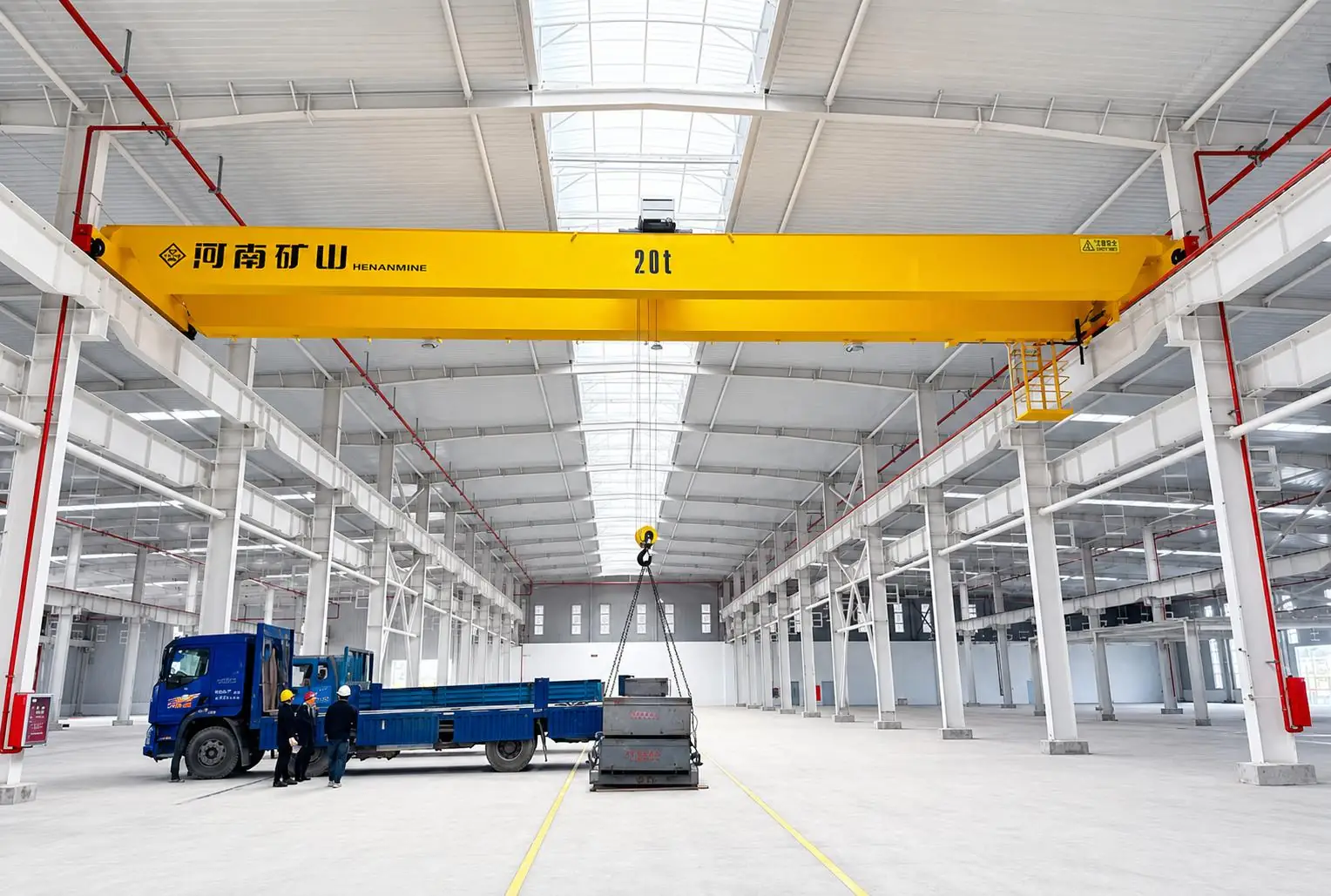
    Henan Mine Crane overhead crane inside a workshop bay
    Henan Mine Crane overhead crane inside a workshop bay
    Project planning notes

    Key points for this crane project.

    1. Application overview
    2. One Hydropower Project, Several Distinct Lifting Duties
    3. Hydropower Plant Crane Configurations
    Read the technical guide

    Application overview

    Primary systems Powerhouse bridge crane and rail-mounted gantry crane

    Engineering basis Critical lift, coverage, duty and civil interfaces

    One Hydropower Project, Several Distinct Lifting Duties

    The powerhouse crane handles the station’s highest-value components. During construction it supports the approved installation sequence for turbine runners, generator rotors and stators, shafts, covers and related assemblies. After commissioning, the same crane must provide the hook coverage and controlled motion required for scheduled outages and major overhaul work.

    Dam and waterway operations require a different machine. A rail-mounted gantry crane may handle intake gates, spillway gates, stoplogs, trash racks or maintenance equipment at positions distributed along the dam crest. Its structure, lifting media, below-the-hook device, outdoor protection and rail interface are therefore designed for the gate schedule rather than for turbine-hall work.

    Installed generating output in MW does not determine crane capacity in tonnes. The crane rating comes from the heaviest verified suspended load, including the component, lifting beam, slings, shackles and other rigging, together with the specified load path and operating method.

    Hydropower Plant Crane Configurations

    01 · Powerhouse Overhead Crane

    A double-girder bridge crane for generating-unit erection, rotor and stator handling, turbine disassembly and scheduled maintenance across the powerhouse bay.

    02 · Pumped-Storage Powerhouse Crane

    A high-capacity, frequently low-headroom arrangement for underground caverns, with project-defined synchronized lifting, precision motion and monitoring functions.

    03 · Dam-Crest Gantry Crane

    A rail-mounted outdoor crane serving multiple gate or stoplog positions, engineered for long travel, wind exposure, drainage, corrosion protection and safe parking.

    04 · Intake Gate and Stoplog Crane

    A lifting system with a purpose-designed spreader or engagement device for intake gates, emergency gates, stoplogs and trash racks at specified slots.

    05 · Tailrace or Draft-Tube Service Crane

    A separate crane or hoist for downstream gates, draft-tube stoplogs and maintenance tasks where access, water level and lifting depth differ from the dam crest.

    06 · Auxiliary Maintenance Crane

    An appropriately rated bridge crane, monorail or electric-hoist system for valve, pump, workshop and service-bay loads that do not require the main crane.

    Compare Hydropower Crane and Gate-Lifting Options

    The correct machine is selected from the load, location and operating sequence. These configurations are complementary and should not be treated as interchangeable quotations.

    Lifting configurationPrimary dutyCritical design inputsProcurement distinction
    Double-girder powerhouse overhead craneTurbine-generator erection and overhaulCritical suspended load, hook approach, lift height, runway reactionsHeavy engineered system integrated with the powerhouse
    Dam or intake gantry craneGate, stoplog and trash-rack handlingGate weight, slot positions, lifting depth, rail layout, outdoor environmentMobile outdoor system with project-specific spreader
    Fixed gate hoistRoutine operation of one dedicated gate or gate groupGate forces, travel, connection points and operating sequenceNot a traveling crane and normally tied to a fixed location
    Electric-hoist maintenance cranePumps, valves and smaller workshop loadsLocal load, headroom, frequency and coverageEconomical for defined service loads, not a substitute for the critical lift

    Select Capacity from the Critical Lift

    For a powerhouse crane, the critical lift may be a generator rotor, stator, turbine runner, main shaft or a combined assembly defined by the turbine supplier. Rated capacity must cover the complete suspended mass, not only the equipment nameplate weight. The lifting beam, hook block, slings, shackles and temporary tooling are included in the lift calculation as applicable.

    Large circular components require verified lifting points, centre of gravity, allowable inclination and clearances through the erection bay. If two hooks, two trolleys or two cranes are involved, permissible load sharing and synchronization must be engineered. Two nameplate ratings cannot simply be added to authorize a combined lift.

    For a gantry crane, the design input includes gate or stoplog dead weight together with seating, friction, water-pressure effects and the approved operating condition. The hydropower designer defines the governing forces and lifting sequence for the crane supplier.

    Critical Lift Data

    Component dimensions, centre of gravity and lifting points

    Technical Specification for a Hydropower Plant Crane

    Final values are established from the EPC drawings, turbine or gate supplier data, structural design and operating philosophy. Henan Mine Crane can develop the general arrangement and technical proposal after the following project inputs are confirmed.

    Specification itemProject information required
    Main and auxiliary capacityHeaviest complete suspended load and separately defined service loads
    Span and runwayRail gauge, runway length, rail profile, support spacing and allowable wheel reactions
    Lifting height or depthHook travel above and below rail, gate-slot depth and required operating elevations
    Hook and spreader coverageGenerating units, erection bay, gate slots, storage racks and maintenance areas
    Duty and load spectrumConstruction lifts, overhaul frequency, gate cycles and expected operating life
    Speeds and positioningNormal and slow speeds, acceleration, stopping behavior and positioning tolerance
    EnvironmentIndoor or outdoor location, humidity, condensation, temperature, corrosion, wind and seismic data
    Electrical and control systemSite power, control station, communications, monitoring and plant-system interfaces

    Precision Control and Safety Architecture

    Controlled Low-Speed Motion

    Variable-frequency drives can provide smooth acceleration, reduced mechanical shock and a specified slow-speed range for alignment over the turbine pit or gate slot.

    Hook Synchronization

    Where the approved lift uses two hooks or lifting points, feedback and control functions are configured to maintain the project-defined relationship and stop on unacceptable deviation.

    Braking and Limits

    Hoisting brakes, upper and lower limits, overload protection, travel limits, buffers and emergency functions are selected to the risk assessment and applicable contract standard.

    Anti-Sway and Monitoring

    Project-defined anti-sway, position feedback, fault recording and operating-data monitoring can support repeatable heavy lifts and maintenance planning.

    Crane and Runway Interface

    Wheel loads, skew control, rail tolerances, end stops and structural deflection criteria are coordinated with the powerhouse or dam civil design.

    Maintenance Access

    Service platforms, guarded access, inspection points, lighting and maintainable component placement are incorporated according to the approved arrangement.

    Hydropower Environment and Gate-Handling Requirements

    An underground powerhouse may combine high humidity, condensation, restricted access and limited headroom. Motors, brakes, enclosures, cable systems, coatings and ventilation are selected for the documented conditions. A low-headroom bridge layout can improve usable hook elevation, but it must be checked together with maintenance access and building reactions.

    Outdoor dam cranes require the specified wind design, storm parking and anchoring arrangement, corrosion-protection system, drainage, low-temperature provisions where applicable and weather-resistant electrical equipment. Wind operating limits and out-of-service securing procedures belong in the operating documentation.

    Gate and stoplog engagement is application-specific. The spreader, latching device, guide system, sensing and lifting media must match the gate geometry and approved procedure. The crane quotation should clearly identify whether spreaders, lifting beams, storage racks and gate-position interfaces are included.

    600t Low-Headroom Pumped-Storage Powerhouse Crane

    Henan Mine Crane supplied a batch of lifting equipment for a pumped-storage power station, including a 600t overhead crane as the core heavy-lifting system. The crane uses a low-headroom structural arrangement developed for the restricted space of an underground powerhouse.

    The equipment incorporates full variable-frequency control, high-precision synchronized operation of two hooks, intelligent anti-sway functions and digital operating-data monitoring. Factory pre-assembly and integrated adjustment were completed before shipment to reduce interface risk during site execution.

    This project demonstrates the engineering priorities of a pumped-storage crane: high-capacity lifting, controlled multi-point handling, efficient use of cavern headroom and traceable operating status. Its 600t rating is project-specific and does not establish the required capacity for another station.

    Engineering Documentation and Quality Control

    Hydropower lifting equipment is integrated with civil works, generating equipment and the construction schedule. The technical submission can be structured around the contract’s document register and inspection plan, with responsibilities clearly assigned before manufacturing.

    Design Package

    General arrangement, wheel loads, hook approaches, mechanism data, electrical architecture and agreed calculation documents.

    Manufacturing Control

    Material traceability, welding and inspection records, dimensional control, mechanism checks and agreed witness points.

    Testing and Handover

    Factory tests, site commissioning, protection verification, load testing, manuals, spare-parts documentation and training records.

    Installation, Commissioning and Lifecycle Service

    Early Civil Coordination

    Confirm runway elevation, support reactions, rails, embedded items, access openings and crane assembly sequence before the structure is closed.

    Site Execution

    Coordinate transport dimensions, underground access, erection equipment, electrical supply, installation supervision and commissioning resources.

    Long-Term Availability

    Establish inspection intervals, lubrication points, rope and brake checks, critical spares and outage support before operational handover.

    The procurement schedule should identify when the crane is required for turbine-generator erection or gate installation, not only the final plant commissioning date. Manufacturing, delivery, runway readiness and site load testing must be aligned with those milestones.

    Hydropower Plant Crane Price and Budget Boundaries

    A hydropower plant crane has no dependable universal list price. These figures are not like-for-like and are not a Henan Mine Crane quotation.

    A meaningful commercial comparison requires every bidder to price the same technical boundary. Henan Mine Crane develops the quotation after the lifting duty, structure, controls and delivery responsibilities are defined.

    Commercial packageItems to confirm
    Crane equipmentBridge or gantry structure, trolley, hoists, hooks, drives, controls and protection
    Below-the-hook equipmentLifting beam, gate spreader, engagement device, slings, storage stand and sensors
    Runway and civil interfaceRails, power feed, embedded parts, support checks and structural modifications
    Project executionInspection, packing, freight, erection, supervision, commissioning and load testing
    Handover and supportDocumentation, training, initial spares, warranty boundary and lifecycle service

    Capacity, span, lifting height, hook arrangement, precision-control functions, environmental protection, destination and Incoterm materially affect the price. Each proposal should state its currency, validity, exclusions and responsibilities for site work.

    Hydropower Plant Crane RFQ Information

    Submit the powerhouse, dam or intake drawings; equipment lift list; maximum suspended load including rigging; component or gate dimensions; span; lifting height or depth; hook approaches; runway information; duty; speed and positioning requirements; power supply; environmental data; destination; applicable standard; delivery schedule; and requested installation and testing scope.

    Frequently Asked Questions

    What type of crane is used in a hydropower powerhouse?

    A double-girder overhead crane is commonly selected for turbine-generator erection and major overhaul. Capacity, hook arrangement, span, lift height and duty are established from the station’s approved lift study.

    How is hydropower plant crane capacity calculated?

    Use the governing component weight plus the complete below-the-hook equipment and rigging, then verify the handling method and load path. The plant’s MW output is not the crane’s rated lifting capacity.

    Why may a pumped-storage crane need a low-headroom design?

    Many pumped-storage units are located in underground caverns where roof elevation and installation access are constrained. A low-headroom arrangement can improve hook elevation, subject to structural and maintenance-clearance checks.

    When are synchronized double hooks required?

    They may be specified when the approved lifting method uses two lifting points on a large component. Required load sharing, permitted deviation, feedback and stopping logic must be defined by engineering.

    What does a dam gantry crane handle?

    Depending on the project, it can handle intake or spillway gates, stoplogs, trash racks and maintenance equipment at multiple positions along a rail. The spreader and lifting sequence are matched to the gate design.

    Is a gate hoist the same as a gantry crane?

    A fixed gate hoist normally serves a defined gate position, while a gantry crane travels along rails and can serve multiple slots or maintenance points. The correct choice follows the operating philosophy.

    What protection is needed for an outdoor hydropower crane?

    The specification may include a suitable coating system, weather-resistant electrics, drainage, wind monitoring, rail clamps or anchoring, lightning protection and low-temperature measures based on actual site conditions.

    Can an existing hydropower crane be replaced or modernized?

    A retrofit is possible after checking the existing runway, wheel loads, clearances, electrical supply, access route and outage window. The retained structure and new equipment require a documented interface assessment.

    How much does a hydropower plant crane cost?

    There is no reliable unit price without capacity, span, lift height, hook or gate-spreader arrangement, controls, environmental protection and supply boundary. An itemized quotation is required for a valid comparison.

    What information is needed for a fast quotation?

    Provide drawings, the critical lift or gate data, span, lift height or depth, runway details, duty, environment, site power, destination, required standard, schedule and installation or commissioning scope.

    Related Hydropower Crane Products and Solutions

    Double-Girder Overhead Crane

    Bridge-crane configuration for appropriately rated powerhouse and maintenance duties.

    Double-Girder Gantry Crane

    Heavy rail-mounted structure adaptable to engineered outdoor hydropower duties.

    Cross-Travel Overhead Crane

    Track-switching access for compatible, specifically engineered maintenance routes.

    Double-Trolley Electric-Hoist Crane

    Coordinated handling option for defined service loads and approved lifting methods.

    Hydropower Industry Solutions

    Explore lifting applications for water conservancy and hydropower projects.

    Share the critical lift, turbine or gate data, plant drawings, runway information, required operating environment, destination and project schedule. Henan Mine Crane will develop a defined equipment configuration and commercial scope for the hydropower facility.

    Discuss the crane arrangement for your project.

    Hydropower lifting needs to serve identified equipment and maintenance positions. Provide component weights, approved lifting points and removal routes so the proposed crane can be coordinated with the station layout. Share the load, available drawings, working cycle and site conditions with Henan Mine Crane so the required configuration and supply boundary can be discussed.

    Related crane configurations

    Explore crane product families and technical parameters ↗

    Updated 2026 · Henan Mine Crane
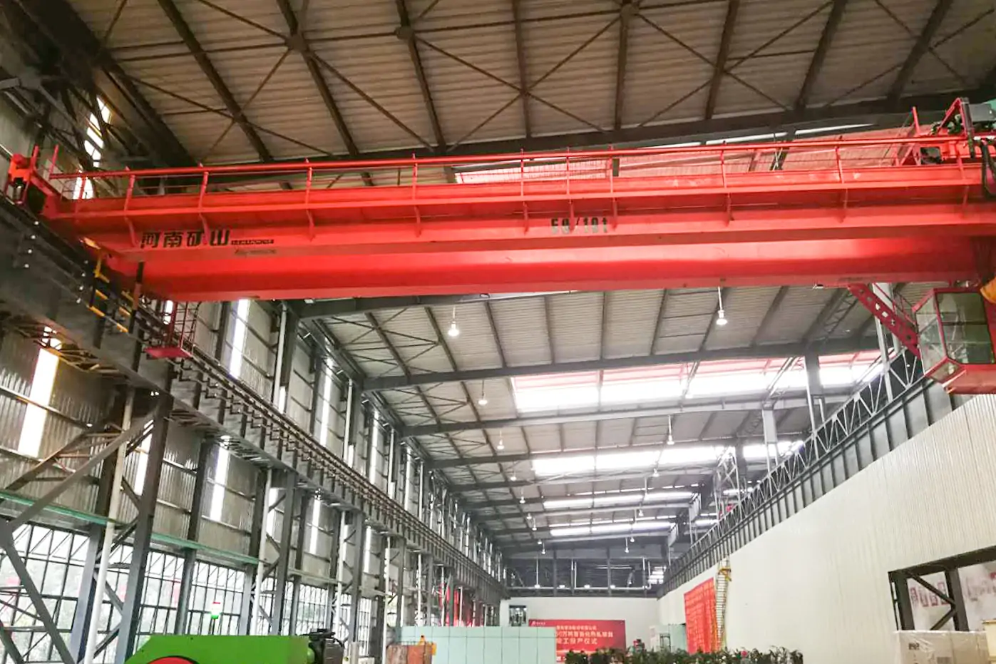
  • Hot Rolling Mill Cranes: Product Transfer and Thermal Exposure

    Hot Rolling Mill Cranes: Product Transfer and Thermal Exposure

    Selection guide

    Hot Rolling Mill Cranes: Product Transfer and Thermal Exposure

    Hot rolling operations need lifting equipment matched to the material and process stage. Describe the product geometry, lifting appliance and operating path so the proposed crane can be assessed for the actual exposure and cycle.

    Henan Mine CraneSelection guide · Updated 2026Crane selection, project scope and operating requirements
    Hot Rolling Mill Crane Systems for Steel Production
    Hot Rolling Mill Crane Systems for Steel Production
    Project planning notes

    Key points for this crane project.

    1. What Is a Hot Rolling Mill Crane?
    2. Hot Rolling Mill Crane Configurations
    3. Compare Hot Rolling Mill Crane Systems
    Read the technical guide

    What Is a Hot Rolling Mill Crane?

    A hot rolling mill crane is an overhead lifting system designed for the production, storage and maintenance tasks surrounding a hot-rolling line. The term covers several purpose-specific cranes because slabs, rolls, plates, coils, tooling and mechanical assemblies create different load shapes, temperatures, cycle frequencies and failure consequences.

    Production cranes may transfer hot or ambient slabs, feed process buffers, move plate or coil products and support continuous material flow. Roll-handling cranes lift work rolls, backup rolls, chocks and roll-changing equipment. Service cranes handle motors, gearboxes, mill stands, guides and other maintenance loads during planned shutdowns. A crane suitable for occasional maintenance is not automatically suitable for repeated production cycles.

    The engineering basis combines maximum gross suspended load, attachment weight, span, lifting height, hook approach, runway length, load spectrum, moves per hour, required speed, positioning tolerance and operating environment. Radiant heat, scale, dust, fumes and restricted maintenance access affect component placement, enclosures, cooling, lubrication and inspection frequency.

    A complete hot-rolling crane proposal therefore defines each crane by process station and coordinates common controls, documentation, components and spare parts across compatible units. Fleet standardization should simplify operation without forcing unlike applications into one technical specification.

    Hot Rolling Mill Crane Configurations

    01 · Slab Transfer Crane

    Moves hot or ambient slabs between continuous casting, cooling, storage and reheating-furnace preparation. Mechanical clamps, magnet beams or approved lifting beams are selected from slab temperature, geometry and stack access.

    02 · Rolling-Line Production Crane

    Supports mill-line material movement, tooling exchange and production interventions. High duty, controlled acceleration, protected electrical equipment and clear operating visibility address the heat, scale and production rhythm.

    03 · Roll-Shop and Roll-Change Crane

    Handles work rolls, backup rolls, chocks, cassettes and roll-changing equipment. Multi-point beams, auxiliary hoists, precise low-speed control and accurate hook approach support alignment and workshop safety.

    04 · Plate Handling Crane

    Uses magnets, clamps or lifting beams for plates and long products after rolling, cooling and finishing. Load flatness, plate temperature, surface quality and multi-magnet control determine the attachment system.

    05 · Coil Handling Crane

    Transfers coils with C-hooks, coil grabs, magnets or engineered beams. Coil eye orientation, width, outside diameter, mass, storage saddles and emergency lowering requirements govern configuration.

    06 · Maintenance and Service Crane

    Provides intermittent access to drives, stands, motors, gearboxes and production equipment. Useful hook approach, low-speed positioning, rigging clearance and shutdown installation access are more important than production throughput.

    Compare Hot Rolling Mill Crane Systems

    Crane SystemPrimary LoadsTypical AttachmentEngineering Priority
    Slab handling craneHot or ambient slabs and bloomsClamp, magnet beam or lifting beamHigh duty, thermal protection and controlled stacking
    Roll handling craneWork rolls, backup rolls, chocks and cassettesRoll beam, tong, hook system or dedicated attachmentPrecise multi-point lifting and alignment control
    Production service craneTooling, mill components and process loadsMain and auxiliary hooks or engineered beamFrequent operation with controlled positioning
    Magnetic plate craneFerromagnetic plates and long steel productsFixed or rotating electromagnetic beamFast pickup with coordinated magnet groups
    Coil handling craneHot- or cold-rolled coils within approved temperatureC-hook, coil grab, magnet or fork attachmentStable coil transfer and accurate saddle placement
    Maintenance bridge craneMotors, gearboxes, stand components and general loadsHook block, sling and removable lifting beamFlexible access for scheduled service work

    Fleet selection rule: build the crane schedule by bay and process task, then standardize controls, component families, documentation and spare parts only where capacity, duty and environment remain compatible.

    Crane Applications Across the Hot Rolling Process

    Process AreaHandling TaskCrane DirectionEngineering Data
    Slab yard and buffer storageReceive, identify, stack and retrieve feed slabsSlab clamp or magnetic-beam craneSlab geometry, residual heat, stack pattern and retrieval sequence
    Reheating-furnace preparationDeliver selected slabs to charging or transfer equipmentHeavy-duty slab or hook-beam craneFurnace schedule, buffer capacity, temperature and transfer interface
    Roughing and finishing millTooling exchange, process intervention and maintenance supportDouble-girder production or service craneHeat, scale, obstruction, operating window and equipment access
    Roll shop and roll storageMove rolls, chocks, cassettes and grinding-shop loadsRoll-handling crane with dedicated beam or hooksRoll dimensions, balance, pickup points and storage stands
    Cooling, cutting and plate finishingTransfer plates between cooling, leveling, cutting and inspectionMagnetic, clamp or beam-equipped cranePlate temperature, flatness, length and surface requirement
    Coil or plate warehouseStack, retrieve and dispatch finished productsCoil, plate or automated warehouse craneInventory logic, throughput, coordinates and vehicle loading

    A rolling-mill fleet can include cranes with similar rated capacities but different mechanism classes and safety functions. Production duty, attachment mass, average load and heat exposure determine the design more reliably than capacity alone.

    Technical Selection and Specification Framework

    These project values demonstrate available engineering directions; final parameters are approved separately for every crane position.

    Specification ItemProject InputRequired Engineering OutputProcurement Control
    Capacity basisMaximum load plus hook block, beam, clamp, magnet, C-hook, sling and every suspended componentNet product mass and gross suspended load are stated separatelyFuture lifts are included only when defined and structurally approved
    Span and coverageRunway rail centers, bridge travel, equipment centers and side approachesDimensioned plan with hook or attachment coverageBuilding width is not substituted for crane span
    Lift and headroomLowest pickup, highest placement, rail elevation, attachment depth and roof obstructionsDimensioned vertical section and maintenance-removal routeHighest hook position and actual load height are verified together
    Duty and load spectrumMoves per hour, average load, full-load frequency, shifts, annual hours and travel distanceCrane and mechanism classification for each positionProduction and maintenance cranes are classified independently
    Temperature and contaminationAmbient air, product temperature, radiant heat, distance, scale, dust, fumes and humidityProtection schedule for structure, motors, brakes, cables, cabinets and lubricationProduct surface temperature is not treated as ambient temperature
    Attachment and load controlHook, beam, clamp, magnet, C-hook, grab or roll-handling equipmentAttachment drawing, mass, operating envelope and interlocksAttachment weight and geometry enter capacity and headroom calculations
    Speed and positioningHoist, trolley, bridge, auxiliary and rotation speeds plus required low-speed rangeVFD, brake, encoder and anti-sway descriptionCycle performance is checked against stopping distance and load stability
    Controls and integrationCabin, radio, local station, PLC, cameras, automation and MES or WMS interfaceControl narrative, I/O schedule and fault-recovery philosophyManual fallback and data boundary are defined before software approval

    Safety and Control Requirements

    Hot-rolling crane safety combines conventional overhead-crane protection with controls for hot products, long loads, production equipment, shared runways and restricted work zones. The final architecture follows the governing design basis and plant risk assessment.

    Hoisting Protection

    Overload limitation, upper and lower limits, brake monitoring, rope guidance, slack-rope protection and low-speed positioning are selected for the load and duty.

    Heat and Electrical Protection

    Heat shields, protected cabinets, temperature-rated cables, cooling or ventilation and suitable lubrication reduce radiant-heat and scale exposure.

    Long-Load and Attachment Control

    Synchronized lifting, attachment status, magnet monitoring, clamp locks and controlled release prevent skew, unequal loading and unintended load loss.

    Travel and Collision Protection

    End limits, buffers, rail sweeps, anti-collision, restricted zones and crane-separation logic address adjacent cranes and fixed production equipment.

    Operator Visibility

    Cabin position, cameras, lighting, warning devices and communication systems provide visibility around mills, stacks, vehicles and maintenance teams.

    Automation and Recovery

    Position feedback, anti-sway, permissive logic, safe stop, fault diagnosis, controlled restart and manual recovery govern automated cycles.

    Maintenance Isolation

    Accessible isolators, lockout points, platforms, walkways and component-removal zones support planned work above active production areas.

    Emergency Operating Plan

    Load retention, controlled lowering, alternate power, emergency braking and production shutdown responsibilities are documented for credible failures.

    Crane Structure, Fleet Logic and Workshop Interface

    Top-running double-girder bridges are widely applied in rolling mills because the structure supports higher capacities, open-winch trolleys, main and auxiliary hoists, service platforms and process attachments. Box-girder design, trolley arrangement and wheel distribution are selected from the span, fatigue duty, headroom and building reactions.

    Production cranes require motion profiles that combine efficient clear travel with controlled approach near the mill, stack or vehicle. Variable-frequency drives, encoders and suitable braking provide low-speed positioning without abrupt acceleration of long slabs, rolls, plates or coils. Maximum speed alone does not determine throughput; pickup, alignment and safe release often control the cycle.

    Fleet planning assigns a unique equipment number, bay, runway, load family and duty to every crane. Common operator interfaces, drive families, brakes, electrical components and documentation can reduce training and spare-parts complexity where ratings remain compatible. Process-specific attachments and protection stay unique to the workstation.

    Runway reactions, rail alignment, conductor location, maintenance platforms, mobile-crane access and removal paths should be coordinated with building and process-equipment design before fabrication. Late interface changes can affect hook coverage, wheel loads and installation cost.

    Project Case: 34-Crane Fleet for Chongqing Panhua Plate

    Henan Mine Crane supplied 34 double-girder overhead cranes for Chongqing Panhua Plate’s intelligent hot-rolling project.

    The cranes serve production, roll handling, tooling, equipment service and maintenance positions. Capacity and duty were assigned by workstation, while compatible controls, documentation and spare-parts planning were coordinated across the fleet.

    Phased engineering, manufacturing and delivery aligned crane availability with workshop construction and commissioning. The case demonstrates the procurement value of one fleet schedule: every crane retains the required span, lift, duty, attachment and environmental protection while project-wide interfaces remain controlled.

    Engineering, Manufacturing and Quality Documentation

    A rolling-mill crane package should connect the approved process data to controlled fabrication, mechanism selection, electrical assembly, testing and handover records. Inspection requirements should be agreed before production release.

    Design Package

    General arrangement, wheel loads, hook approaches, mechanism class, attachment drawing, electrical demand and control narrative.

    Structural Records

    Material identification, approved welding procedures, welder qualifications, dimensions and specified non-destructive examination.

    Mechanism Data

    Motor, gearbox, brake, drum, rope, wheel, bearing, coupling and lubrication information matched to the declared duty.

    Electrical Documents

    Single-line diagram, schematics, I/O schedule, drive data, protection settings, network boundary and configured parameters.

    Inspection and Tests

    Inspection plan, witness points, dimensions, mechanisms, brakes, limits, alarms, attachment functions and contracted load testing.

    Fleet Handover

    Crane-numbered manuals, final drawings, test records, spare-parts lists, maintenance schedules and commissioning data.

    Installation, Commissioning and Lifecycle Planning

    Fleet Engineering Schedule

    List every crane by bay, quantity, capacity, span, lift, duty, attachment, power, control mode and required drawing, manufacturing and delivery date.

    Runway and Site Verification

    Confirm rail centers, elevation, alignment, support capacity, conductor arrangement, crane separation, end stops and installation access before shipment.

    Phased Packing and Delivery

    Match bridge sections, trolleys, panels, attachments and loose parts to the equipment number and destination bay. Delivery batches follow site readiness.

    Erection and Alignment

    Plan mobile-equipment access, assembly areas, lifting method, rail checks, conductor installation, attachment assembly and work near process equipment.

    Commissioning and Acceptance

    Verify brakes, limits, drives, synchronization, controls, alarms, communications and attachment functions before load and process trials.

    Operator and Maintenance Training

    Cover operating modes, warning responses, daily checks, isolation, fault recovery, attachment inspection and crane-specific limitations.

    Preventive Maintenance

    Inspection intervals reflect load cycles, heat, scale, dust and production consequence. Brakes, ropes, wheels, rails, cables and attachments receive defined wear limits.

    Fleet Spare-Parts Planning

    Standardize compatible brake, drive, contactor, encoder, sensor, limit, rope and seal families while retaining crane-specific critical spares.

    Hot Rolling Mill Crane Budget and Supply Scope

    Hot-rolling production cranes, roll-change cranes and maintenance cranes have different loads and operating cycles. Budget each role separately, including the lifting attachment and the plant interfaces needed for that role.

    Budget packageMain scope inputs
    Bridge, trolley and attachmentGross load, span, hook travel, load geometry and handling method
    Operating duty and environmentLifts per hour, load spectrum, speeds, heat, scale, dust and cooling requirements
    Control and fleet integrationPositioning, crane coordination, production interfaces and recovery arrangements
    Site and lifecycle supportRunways, electrical supply, erection, testing, training, maintenance access and spares

    Request an itemised proposal from Henan Mine Crane using the same production schedule and supply boundary for all bidders. Quote freight, civil works, installation and commissioning explicitly rather than assuming that an equipment price includes the completed mill installation.

    Information Required for a Hot Rolling Mill Crane Quote

    A complete request should contain one crane schedule covering every workshop and process position. Building drawings, equipment layouts, load sketches and project milestones should accompany the following data.

    Crane Schedule

    Quantity, equipment number, bay, capacity, span, lifting height, runway length, headroom, hook approach and required delivery sequence.

    Load and Attachment

    Load name, maximum and typical mass, dimensions, center of gravity, pickup points, temperature, attachment type and attachment mass.

    Duty and Throughput

    Moves per hour, load spectrum, shifts, annual hours, full-load frequency, travel distance, target cycle and production consequence.

    Motion and Control

    Hoist, trolley and bridge speeds, low-speed range, main and auxiliary hooks, cabin or radio control, anti-sway and positioning tolerance.

    Environment

    Ambient temperature, product temperature, radiant heat, distance, scale, dust, fumes, humidity, corrosion and electrical enclosure requirements.

    Runway and Building

    Rail section, runway beam, column spacing, rail elevation, wheel-load limits, conductor position, obstructions and installation access.

    Automation and Interfaces

    PLC or MES communication, I/O, equipment interlocks, stack or target coordinates, cameras, data records and manual recovery mode.

    Commercial and Acceptance Scope

    Trade term, packing, freight, runway, installation, load testing, third-party inspection, training, spares and schedule milestones.

    Hot Rolling Mill Crane FAQ

    Which crane types are required in a hot rolling mill?

    Typical systems include slab transfer cranes, production bridge cranes, roll-handling cranes, plate or coil cranes and maintenance cranes. The exact fleet follows process layout, load families and maintenance strategy.

    How is crane capacity selected?

    Capacity includes the maximum load and every suspended attachment. Roll beams, clamps, magnets, C-hooks, hook blocks and rigging enter the gross-load calculation. Future lifts require defined geometry and duty.

    Can one crane handle slabs, rolls and coils?

    A shared crane is possible only when capacity, attachment changes, headroom, duty, heat exposure and operating routes remain compatible. Dedicated process cranes normally provide clearer safety and throughput for frequent tasks.

    What duty class suits a rolling mill crane?

    Duty follows load spectrum, moves per hour, shifts, travel distance and operating consequence. A production crane and an intermittent maintenance crane can require different mechanism and structural classifications at the same capacity.

    How is radiant heat addressed?

    Thermal design considers product surface temperature, ambient air, exposure distance and duration. Shields, protected cabinets, suitable cables, component placement, cooling and lubrication are selected from the actual heat map.

    Can rolling mill cranes integrate with MES?

    PLC-based systems can exchange task, permissive, status, position and fault data with plant systems. Interface ownership, protocol, I/O, cybersecurity boundary and manual recovery are defined before implementation.

    What attachment is suitable for steel plate?

    Magnets support fast handling of approved ferromagnetic plates, while clamps or beams may suit restricted magnetic use or specific surface requirements. Temperature, air gap, plate range and power-loss strategy govern selection.

    How should roll changes be handled?

    A dedicated roll beam or multi-point arrangement should match roll centers, mass, balance and storage stands. Synchronized lifting, precise low-speed motion and clear exclusion zones support controlled alignment.

    Can a large crane fleet be delivered in phases?

    Drawing approval, production and shipment can follow workshop readiness. Every component and document should retain the correct crane number, bay and delivery batch throughout the project.

    What should a commercial quotation include?

    The proposal should identify crane and attachment scope, technical parameters, runway interface, heat protection, controls, documentation, testing, packing, freight, erection, commissioning, training, spares, exclusions and schedule.

    Related Steel Mill Crane Products

    Compare process-crane families after load, duty, temperature, attachment and workshop interfaces have been defined. Each configuration is finalized through project-specific engineering.

    Slab Handling Crane

    Process crane for hot or ambient slabs in transfer, stacking, storage and rolling-mill feed operations.

    Electromagnetic Hanging Crane

    Rotating magnetic-beam system for approved plates, profiles and magnetically responsive steel products.

    Upper-Rotating Magnetic Crane

    Slewing-trolley magnetic crane for multi-angle positioning across production and warehouse bays.

    Double-Girder Bridge Crane

    Customizable bridge platform for higher capacity, longer span, maintenance and specialized attachments.

    Metallurgical Bridge Crane

    Heavy-duty overhead crane family developed for heat, dust and intensive metallurgical service.

    Electromagnetic Bridge Crane

    Magnetic overhead crane platform for approved plates, billets and other ferromagnetic materials.

    Discuss the crane arrangement for your project.

    Submit the crane schedule, workshop layouts, load list, attachment requirements, duty, temperature conditions, runway data, power supply, controls, project milestones, destination and delivery boundary. Henan Mine Crane will prepare a coordinated technical configuration and commercial quotation.

    Related crane configurations

    Explore crane product families and technical parameters ↗

    Updated 2026 · Henan Mine Crane
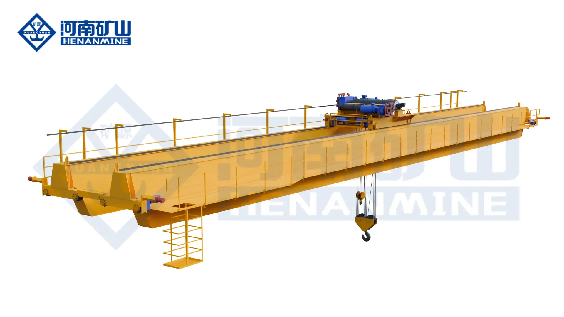
  • Heat Treatment Cranes: Furnace Interfaces and Handling Sequence

    Heat Treatment Cranes: Furnace Interfaces and Handling Sequence

    Selection guide

    Heat Treatment Cranes: Furnace Interfaces and Handling Sequence

    Heat treatment lifting depends on the workpiece and the way it enters or leaves the process. Define the attachment, working positions and exposure conditions so crane coverage and controls can be developed around the furnace operation.

    Henan Mine CraneSelection guide · Updated 2026Crane selection, project scope and operating requirements
    Heat Treatment Crane Systems
    Heat Treatment Crane Systems
    Project planning notes

    Key points for this crane project.

    1. Application overview
    2. What Is a Heat Treatment Crane?
    3. Heat Treatment Crane Applications
    Read the technical guide

    Application overview

    Published ranges describe the Henan Mine Crane quenching-crane platform, not a universal model. The approved project specification governs final capacity, speed, span, lift, classification and performance.

    What Is a Heat Treatment Crane?

    A heat treatment crane is an overhead process crane designed to move workpieces, baskets, racks or fixtures between furnaces, quench tanks, wash stations, tempering equipment, cooling positions and inspection areas. The term includes general furnace-transfer cranes as well as high-speed quenching cranes that must immerse a hot load within a specified time and motion profile.

    The distinction matters. A general double-girder crane may be suitable for controlled transfer where the process has no rapid immersion requirement and the thermal, vapor, splash and duty conditions remain within its engineered limits. A quenching overhead crane requires a verified lowering speed, brake and overspeed architecture, power-loss response, load stability, bath clearance and recovery method. Substituting a general-purpose crane without this process review can compromise both treatment results and safe load control.

    Heat treatment cranes handle solid workpieces. They are not automatically suitable for ladles or molten metal. A foundry or casting crane uses a different load path and safety architecture. Henan Mine Crane develops heat-treatment systems from its quenching crane, metallurgical bridge crane and double-girder bridge crane platforms according to the actual process duty.

    Heat Treatment Crane Applications

    Vertical Shaft and Roll Quenching

    Lift long shafts, rolls or rotors in a controlled vertical orientation and lower them into a tank while maintaining clearance, stability and the specified immersion profile.

    Batch and Basket Quenching

    Transfer loaded baskets, racks or fixtures from the furnace to water, polymer, brine or oil baths with repeatable pickup, travel, immersion and drainage positions.

    Die and Mold Heat Treatment

    Handle dies, mold blocks and tool steel between heating, quenching, tempering and inspection stations with an attachment matched to geometry and hot-load behavior.

    Gear, Ring and Bearing Production

    Move rings, gears, rollers and bearing components through controlled thermal cycles where positioning, batch traceability and repeatable transfer time are required.

    Forging Heat-Treatment Bay

    Transfer heavy forgings, flanges and pressure-vessel parts from furnaces to cooling or quenching stations, including single- or dual-point handling where approved.

    Automatic Heat-Treatment Line

    Coordinate crane movements with furnace doors, tank covers, agitation systems, recipes, tracking databases and defined safe zones through an approved signal matrix.

    Components and Operating Principle

    1. Bridge and end carriages: distribute trolley, load and dynamic reactions to the runway while maintaining the required approach to furnaces and tanks.
    2. Process hoist: provides normal lifting, rapid or controlled immersion, recovery and low-speed positioning through a motion profile matched to the treatment recipe.
    3. Brakes and monitoring: use the project-defined service, holding and emergency functions, with overspeed, position, limit and load supervision where required.
    4. Below-hook equipment: may include baskets, racks, spreaders, lifting beams, tongs, clamps or vertical lifting fixtures engineered for the hot workpiece and bath.
    5. Controls and interfaces: coordinate bridge, trolley and hoist motion with furnace doors, tank equipment, restricted zones, process recipes and operator commands.
    6. Environmental protection: addresses radiant heat, steam or vapor, splash, corrosion, scale, water drainage, oil mist, cable routing, enclosure selection and maintenance access.

    Rated-load basis: crane capacity must cover the heaviest workpiece plus the basket, rack, lifting beam, chains, fixture, hook block and every other suspended item. It must also account for retained liquid, eccentric loading, dual-point load sharing and the approved dynamic case. Workpiece mass alone is not the crane rating.

    Heat Treatment Crane Selection Considerations

    Selection begins with the treatment cycle and complete load path. Capacity, span and lift are necessary, but they do not define immersion performance, safe recovery or the interface with the furnace and tank.

    Load and Orientation

    Minimum, typical and maximum gross load; dimensions; center-of-gravity range; vertical or horizontal orientation; single or multiple pickup points; fixture mass and retained liquid.

    Transfer and Immersion Time

    Furnace-door release to bath entry, travel distance, required lowering profile, entry depth, dwell, agitation interaction, withdrawal speed and drainage time.

    Temperature and Exposure

    Workpiece temperature at pickup, furnace opening duration, radiant-heat map, steam or vapor plume, splash envelope and measured temperatures at ropes, brakes, motors, sensors and panels.

    Bath and Medium

    Tank length, width, depth and freeboard; water, polymer, brine or oil; operating temperature; agitation; covers; overflow; ventilation; fire strategy; drainage and contamination controls.

    Duty and Availability

    Lifts per hour, starts and reversals, shifts, annual hours, load spectrum, required production availability, maintenance windows and the consequence of an interrupted batch.

    Power Loss and Recovery

    Safe load state, controlled lowering or lifting, emergency power source, brake behavior, manual recovery, tank access and the permitted response at each point in the process cycle.

    Building and Runway

    Rail-center span, runway length and elevation, available headroom, hook approaches, wheel-load limits, furnace and tank obstructions, ventilation ducts and installation access.

    Controls and Acceptance

    Cabin, radio or automatic operation; positioning tolerance; anti-sway; recipe signals; traceability; safe zones; FAT, SAT and representative-load test criteria.

    Heat Treatment Crane Configurations Compared

    The correct configuration follows the process motion, load orientation and failure response. The table separates common arrangements that may look similar in a workshop layout but serve different duties.

    ConfigurationTypical ProcessLoad ArrangementDefining Engineering Requirement
    General Heat-Treatment Handling CraneFurnace charging, extraction, tempering and cooling transferHook, beam, basket or fixtureThermal exposure, duty, attachment and controlled low-speed positioning
    Vertical Quenching CraneShaft, roll, rotor or long-part immersionVertical fixture with guided or stabilized pickupClearance, vertical stability, immersion speed and emergency recovery
    Batch or Basket Quenching CraneGrouped components or mixed production batchesBasket, rack or multi-point spreaderGross batch mass, even support, retained liquid, drainage and repeatable pickup
    Automatic Quenching-Line CraneRecipe-driven furnace and tank sequenceStandardized fixtures with identificationPositioning, anti-sway, signal ownership, traceability and defined fallback modes
    Heavy Forging Heat-Treatment CraneLarge forgings, flanges, rings and pressure componentsHeavy beam, clamp, tongs or dual-point rigHigh gross load, eccentric cases, attachment behavior and intensive duty
    Foundry or Casting CraneMolten-metal ladle transferLadle beam and auxiliary hookMolten-metal load path and applicable foundry requirements

    Preliminary Heat Treatment Crane Specifications

    These values summarize the published Henan Mine Crane quenching-crane platform and common project variables. They support an initial enquiry; they are not a substitute for the approved data sheet.

    ParameterRequired Project Confirmation
    Rated CapacityMaximum gross suspended load and all abnormal load cases
    SpanRail-center dimension, runway condition and hook approaches
    Lifting HeightHighest pickup, lowest immersion point, freeboard and hook-block geometry
    Hoisting SpeedNormal lift, creep, immersion, withdrawal and emergency motion profiles
    Working ClassificationApplicable classification system, load spectrum, cycles and design life
    Power SupplySite voltage, frequency, earthing, short-circuit data and emergency source
    Control ModeOperating philosophy, visibility, safe zones, interfaces and fallback mode
    PositioningTolerance at furnace, tank and fixture; speed; sway; load and environmental conditions

    Quenching Cycle and Motion Engineering

    A useful performance specification describes the entire motion from furnace pickup to bath exit. It states when timing begins, the path and acceleration limits, the liquid-entry point, the required immersion depth, permitted swing, dwell time, withdrawal profile and the condition in which the load may travel again. A single maximum hoist speed does not prove that the cycle can be achieved.

    1. Pickup and confirmation: verify fixture engagement, gross load and permission to leave the furnace zone.
    2. Transfer: use the approved bridge, trolley and hoist profile while controlling sway and clearance.
    3. Immersion: transition to the specified lowering mode and reach the defined depth within the treatment window.
    4. Bath dwell: hold or move the load only as permitted by the recipe, tank agitation and fixture design.
    5. Withdrawal and drainage: recover at the defined speed, stop at the drainage position and contain liquid before travel.
    6. Completion and traceability: release the route only after the load, tank and downstream station meet the agreed conditions.

    Power-loss scenario: the specification must define the safe response before the load leaves the furnace, during transfer, during immersion, while submerged and during withdrawal. Emergency power, redundant functions or a manual recovery arrangement are selected from the process risk assessment and site infrastructure.

    Bath Media, Heat, Vapor and Corrosion Protection

    Workpiece temperature is not the same as crane ambient temperature. Thermal design uses exposure at each component, including radiation from the load and furnace, hot vapor above the bath, splash, air movement and the time spent in each zone.

    Process MediumCrane Interface to DefineProject Measures to Evaluate
    WaterSteam plume, splash, condensation and retained waterDrainage, corrosion system, enclosure and cable selection, visibility and ventilation
    Polymer SolutionConcentration, residue, compatibility and cleaning methodMaterial compatibility, wash-down boundaries, slip control and maintenance access
    BrineSalt mist, splash and accelerated corrosionProtective coating, stainless or protected hardware where justified, sealed equipment and inspection intervals
    OilVapor, mist, surface contamination and fire riskSite fire strategy, ventilation, electrical-area review, emergency response and contamination control

    Oil Quenching Requires a Site-Specific Fire Review

    Oil type, flash characteristics, bath temperature, vapor control, ignition sources, fire detection, suppression, ventilation and emergency procedures are defined by the process owner and applicable local requirements. Electrical-area classification and equipment selection follow that review; they should not be assumed from the word “oil” alone.

    The crane supply boundary should state who provides the tank cover, ventilation, fire system, process sensors, emergency power, cable interfaces, containment and final integrated test.

    Attachments, Fixtures and Load Orientation

    Baskets and Racks

    Define empty and loaded mass, support points, deformation limits, liquid flow, drainage, center of gravity, maximum temperature and positive engagement.

    Lifting Beams and Spreaders

    Confirm hook spacing, headroom, load equalization, hot-zone exposure, proof testing, storage position and compatibility with every approved load family.

    Tongs and Clamps

    Establish the gripping principle, acceptable surface contact, engagement confirmation, loss-of-force response and behavior at process temperature.

    Vertical Lifting Fixtures

    Control long-load alignment, lateral stability, tank clearance and pickup verification through the full lift and immersion depth.

    Dual-Point Suspension

    Specify capacity split, permitted tilt, synchronization tolerance, load sharing, reeving behavior and the response to unequal motion or sensor loss.

    Attachment Changeover

    Plan storage, identification, mechanical and electrical connections, interlocks, inspection status and the process for preventing the wrong attachment selection.

    Complete load path: bundle bands, temporary ties and handling aids are not treated as lifting points unless they are designed, documented and approved for that purpose. The engineered attachment must retain every component throughout transfer, immersion, agitation, withdrawal and drainage.

    Manual, Semi-Automatic and Automatic Control

    Control LevelOperator RoleTypical FunctionsData Needed Before Quotation
    ManualDirectly commands each motion from cabin or radioVariable speed, limits, overload monitoring, permissives and status displaySight lines, operator location, cycle sequence and restricted zones
    Semi-AutomaticSelects a destination or cycle and supervises executionStored positions, assisted route, automatic immersion profile and interlocksPosition list, tolerance, command ownership and manual takeover rules
    AutomaticSupervises production and handles exceptionsRecipe routing, load tracking, anti-sway, interface handshake, diagnostics and recordsFunctional specification, I/O list, network, cybersecurity boundary and recovery modes

    Interface Matrix

    Every exchange with the furnace, door, tank cover, agitation system, ventilation, process controller and plant network should identify the signal owner, permissive condition, timeout, fault reaction, reset authority and safe state. Automatic travel should be blocked when equipment is not in the agreed position.

    Remote access, event records, user permissions and network segregation are agreed with the plant’s operational technology policy. Automation scope includes the practical means to recover a load after a sensor, communication or drive fault.

    Design Basis, Inspection and Acceptance

    The contract identifies the governing country, crane classification, structural and mechanism rules, electrical requirements, below-hook device standard, local registration and inspection route. Depending on destination and project requirements, the design basis may reference ISO 4301 classification; EN 13001, EN 15011 and EN 13155; or CMAA 70 with applicable ASME B30.2, B30.20 and BTH-1 provisions. Local laws and the signed specification take precedence.

    Design Review

    Approved load cases, mechanism classification, fatigue basis, runway reactions, motion profile, attachment, heat and environmental map, failure analysis and interface schedule.

    Factory Testing

    Material and fabrication records, dimensional checks, mechanism and brake tests, panel and software checks, simulated I/O, alarms, limits and document review under the agreed inspection plan.

    Site Acceptance

    Installation and alignment checks, proof and functional tests, representative fixture or load trials, process sequence, emergency response, interfaces, recovery, training and handover documents.

    Published Solution and Adjacent Project Experience

    YH Quenching-Crane Product Platform

    Henan Mine Crane publishes a quenching-crane platform for rapid immersion of high-temperature workpieces, with project options for thermal protection, dual braking, emergency power, manual or PLC control and automatic positioning. Published applications include steel rolls, mold steel, shafts, gears, flanges, bearing components and high-strength fasteners.

    The platform description establishes an engineering starting point. Project performance is confirmed only in the signed technical proposal and acceptance criteria.

    Adjacent High-Temperature and Automation References

    Published Henan Mine Crane hot-rolled steel and fully automatic metallurgical-crane projects demonstrate adjacent capabilities in heavy-duty bridge engineering, thermal environments, positioning and production-line integration.

    These adjacent references are not presented as heat-treatment deliveries. They illustrate transferable engineering disciplines; the furnace, bath, fixture and quenching cycle require separate project validation.

    Evidence boundary: product ranges on this page come from published Henan Mine Crane information. Application descriptions explain engineering routes. Adjacent project photographs show related high-temperature or automated crane work and do not represent the exact configuration offered for every heat-treatment enquiry.

    Heat Treatment Crane Price and Budget Scope

    Purpose-built heat treatment and quenching cranes are normally priced by project. A public web review completed on 20 September 2026 found specialist suppliers presenting these cranes through request-for-quotation pages rather than comparable numeric prices. No credible like-for-like public price was found for a complete quenching-crane system with a defined load, immersion cycle, bath medium, emergency strategy and delivery scope.

    The listing described a general workshop or warehouse crane, not a heat-treatment duty, and is therefore not a dependable budget for a quenching system. A valid comparison must normalize the technical and commercial scope.

    Market ReferencePublished Price StatusHow to Use It
    Specialist Heat-Treatment or Quenching CraneProject quotation / RFQObtain a configuration-based proposal against one common duty specification
    Public Specialist Platform PagesCapacity and dimensional ranges published; numeric price generally not publishedUseful for identifying available engineering envelopes, not for installed-project budgeting
    Henan Mine Crane Heat Treatment SystemProject quotationPrice follows approved process, crane, attachment, interface and supply-boundary data

    Main Cost Drivers

    Comparable quotation rule: issue the same load matrix, motion cycle, bath data, duty, layout, standards and supply boundary to every supplier. Require explicit inclusions, exclusions, utilities, interface responsibilities, testing scope, spare parts and commercial terms.

    Information Required for a Heat Treatment Crane Quote

    A complete enquiry allows the crane structure, hoist, attachment, thermal protection, emergency response, controls, runway reactions and commercial scope to be priced on the same basis.

    Workpiece and Fixture

    Minimum, normal and maximum mass and dimensions; material; temperature at pickup; center of gravity; orientation; basket, rack, spreader or clamp data; drawings and photographs.

    Treatment Cycle

    Furnace pickup point, route, maximum transfer time, immersion depth and profile, dwell, agitation, withdrawal, drainage, destination, cycles per hour and load spectrum.

    Tank and Environment

    Bath medium and temperature; tank dimensions and freeboard; covers and agitation; vapor, splash and ventilation; furnace and ambient heat data; corrosion and fire strategy.

    Workshop and Runway

    Rail-center span, runway length and elevation; required lift; headroom; approaches; rail and beam data; wheel-load limits; cross-section, equipment layout and installation access.

    Controls and Emergency Strategy

    Manual, assisted or automatic mode; positions and tolerances; interface signals; cameras; anti-sway; power-loss response; emergency source; recovery access and safe states.

    Commercial and Compliance Scope

    Destination, power supply, standards, inspection route, Incoterm, freight, installation, electrification, commissioning, testing, training, spares, documentation and warranty requirements.

    Frequently Asked Questions

    Is a heat treatment crane the same as a quenching crane?

    A quenching crane is one type of heat treatment crane. It is specifically engineered for timed immersion and recovery. Heat-treatment handling can also include furnace transfer, tempering, annealing and cooling operations without rapid immersion.

    How is heat treatment crane capacity calculated?

    Start with the heaviest workpiece and add the basket, fixture, beam, rigging, hook block, retained liquid and every suspended accessory. Then evaluate eccentric loading, multi-point load sharing, dynamic motion and abnormal cases.

    Can a standard overhead crane perform quenching?

    Only if a dedicated engineering review confirms the complete process. Immersion time, hoist profile, brakes, power-loss response, thermal exposure, vapor, splash, corrosion, fixture, clearance and duty can require a purpose-built system.

    Which quenching media can the crane serve?

    Water, polymer solution, brine and oil can be considered. Each medium creates different vapor, splash, corrosion, contamination, ventilation and fire conditions, so the bath data and site risk assessment are required.

    How much does a heat treatment crane cost?

    Specialist suppliers normally quote by project, and the September 2026 public review found no dependable like-for-like numeric price. Capacity, immersion performance, attachment, environment, redundancy, automation, runway and installed scope must be defined first.

    What happens if power fails during quenching?

    The required response is defined for every cycle stage. Depending on the risk assessment, the solution may use emergency power, selected redundant functions, controlled recovery and a documented manual procedure.

    Can the crane integrate with furnaces and tank controls?

    Integration can include door, cover and agitation interlocks, route permissions, load identification, recipe selection, position confirmation, event records and plant-system communication under an approved functional specification.

    What should be tested before handover?

    Tests cover rated and proof loads, brakes, limits, overspeed and overload functions, process motion, positioning, attachment, interfaces, safe states, emergency response, manual recovery and representative treatment sequences.

    Related Heat-Treatment and Metallurgical Crane Products

    Each product platform serves a different process load and risk profile. Final selection follows the material, temperature, movement, environment, duty and site data.

    Quenching Crane

    Specialized platform for rapid workpiece immersion, bath dwell, recovery and heat-treatment line integration.

    Metallurgical Bridge Crane

    Heavy-duty bridge platform for declared high-temperature and metallurgical process environments.

    Double-Girder Bridge Crane

    Configurable platform for furnace transfer and general handling where rapid immersion is not required.

    Double-Girder Casting Crane

    Dedicated molten-metal handling platform when foundry ladle transfer is separately in scope.

    Automatic Metallurgical Crane

    Integrated control reference for defined production routes, positioning and plant-system communication.

    Special Metallurgical Overhead Crane

    Project-specific lifting platform for demanding metallurgical process conditions and safety requirements.

    Submit the workpiece and fixture matrix, pickup temperature, furnace-to-bath sequence, transfer and immersion timing, bath medium and dimensions, duty cycle, span, lift, runway data, control level, power-loss strategy, destination and supply boundary. Henan Mine Crane will prepare a configuration-based technical and commercial proposal.

    Discuss the crane arrangement for your project.

    Heat treatment lifting depends on the workpiece and the way it enters or leaves the process. Define the attachment, working positions and exposure conditions so crane coverage and controls can be developed around the furnace operation. Share the load, available drawings, working cycle and site conditions with Henan Mine Crane so the required configuration and supply boundary can be discussed.

    Related crane configurations

    Explore crane product families and technical parameters ↗

    Updated 2026 · Henan Mine Crane
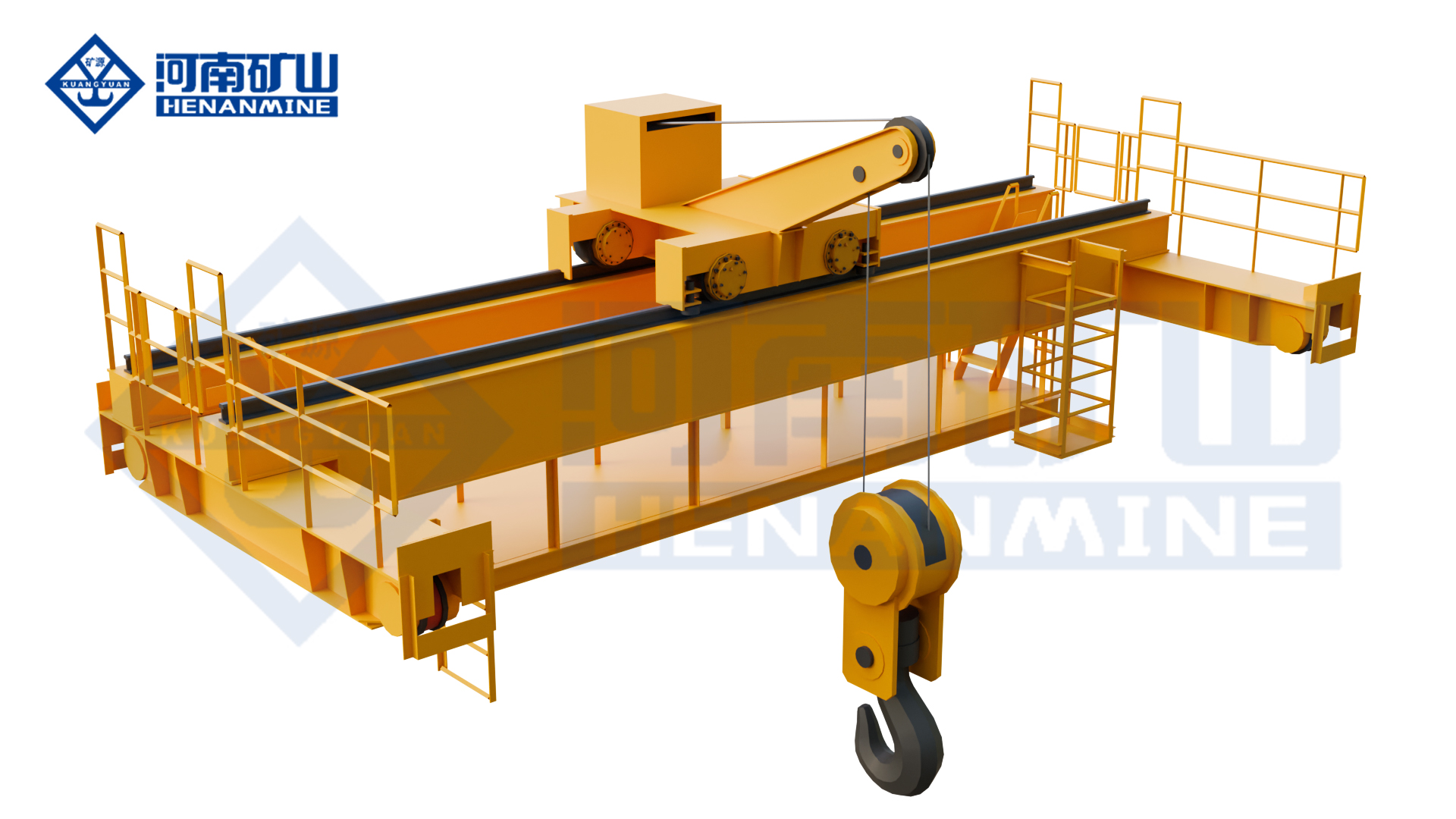
  • Galvanizing Line Cranes: Immersion Tasks and Process Atmosphere

    Galvanizing Line Cranes: Immersion Tasks and Process Atmosphere

    Selection guide

    Galvanizing Line Cranes: Immersion Tasks and Process Atmosphere

    A galvanizing line needs a lifting arrangement coordinated with its tanks and transfer stages. Describe the workpiece, lifting tools and local atmosphere so equipment protection and movement requirements can be reviewed together.

    Henan Mine CraneSelection guide · Updated 2026Crane selection, project scope and operating requirements
    Galvanizing Line Crane
    Galvanizing Line Crane
    Project planning notes

    Key points for this crane project.

    1. What Is a Galvanizing Line Crane?
    2. Galvanizing Line Crane Types
    3. Compare Galvanizing Line Crane Configurations
    Read the technical guide

    What Is a Galvanizing Line Crane?

    A galvanizing line crane is an overhead process crane engineered to move steel products, racks, baskets or crossbeams through batch hot-dip galvanizing operations. It may execute loading, tank-to-tank transfer, controlled immersion, dwell, withdrawal, drainage, cooling and unloading. Its motions can form part of the production recipe, so the crane must be specified as process equipment rather than as a general workshop lifting machine.

    A galvanizing facility may require several distinct crane duties: one or more production-line cranes for the chemical tanks and zinc kettle, a loading or finishing crane outside the aggressive process zone, and a separate maintenance crane for the kettle, furnace equipment, lifting beams and removable plant components. Combining incompatible duties without a route, availability and environmental review can restrict production or create an unsuitable protection concept.

    Capacity, span and lifting height are only the starting parameters. A procurement specification also requires the complete suspended mass, workpiece geometry, lifting-point arrangement, tank coordinates, immersion angle, process speeds, cycle histogram, chemical and thermal exposure, automation interfaces, safe-recovery philosophy and responsibility boundary.

    Galvanizing Line Crane Types

    01 · Single-Girder Process Crane

    A compact bridge with one or two hoists for moderate suspended loads, shorter spans and defined production cycles. Hoist synchronization, service access, corrosion protection and the required duty class must be verified before selecting this lower-self-weight arrangement.

    02 · Double-Girder Process Crane

    A robust platform for longer spans, frequent cycles, higher suspended loads, service walkways and process-specific trolley arrangements. It provides greater flexibility for automation, redundant positioning feedback and maintainable component layouts.

    03 · Twin-Hoist or Twin-Trolley Crane

    Two lifting points stabilize long workpieces and support controlled entry, withdrawal and drainage angles. The control system defines synchronized lifting, permitted differential height, restricted independent motion and fault recovery.

    04 · Automated Galvanizing Transport System

    One or more cranes execute recipe-based routes using position feedback, tank handshakes, inter-crane zoning, production tracking and controlled recovery modes. The crane, line PLC and supervisory-system boundaries are defined before quotation.

    05 · Cantilever Zinc-Pot Crane

    A project-defined cantilever extends hook coverage beyond the normal bridge envelope for empty-pot handling, furnace-area service and equipment maintenance. It is not automatically a substitute for the production transport crane.

    06 · Loading, Finishing and Maintenance Crane

    A single- or double-girder overhead crane for racking, unloading, inspection, component removal and workshop service. Environmental protection is selected for its actual zone, while process-crane features are included only when the duty requires them.

    Compare Galvanizing Line Crane Configurations

    The correct configuration follows the workpiece, process route, immersion method, cycle demand and exposure zone. Cranes with the same rated capacity may have different hoist arrangements, controls, protection systems and commercial scope.

    Crane ConfigurationPrimary DutyLifting ArrangementCritical Design Basis
    Single-Girder Process CraneModerate-load process transfer on a defined lineOne or two electric hoists with project-specific beam or rack interfaceSpan, duty, synchronization, headroom, environment and maintenance access
    Double-Girder Process CraneFrequent cycles, longer spans, higher loads and automationTop-running trolley with single, twin or process-specific hoistingCycle histogram, wheel loads, service access, motion control and plant interfaces
    Twin-Hoist or Twin-Trolley CraneLong-load stabilization, tilting and controlled drainageTwo lifting points operating synchronously or within a restricted differentialLoad stiffness, lifting-point spacing, maximum angle, feedback and fault response
    Cantilever Zinc-Pot CranePot replacement, furnace maintenance and extended hook coverageProject-defined cantilever with hook or maintenance lifting beamComponent weights, outreach, headroom, structural forces and service procedure
    Integrated Multi-Crane SystemHigh-throughput lines, parallel tanks and separated process zonesMultiple coordinated cranes, transfer points and buffer stationsRoute simulation, collision zones, queue logic, availability and recovery strategy

    Selection principle: define the crane from the complete process duty. A general overhead crane does not become a galvanizing process crane by adding corrosion-resistant paint, and two standard hoists do not provide controlled tilting without the required synchronization, permissions and fault response.

    Match the Crane to the Galvanizing Process Area

    A plant-wide handling study records every pickup point, tank coordinate, dwell time, travel route, attachment, restricted zone and line interface. It also separates loading, production and maintenance duties that cannot share one machine because of environmental exposure, incompatible working envelopes or required availability.

    For the pretreatment tanks, the study addresses corrosive vapor, liquid carryover, drainage, tank-rim clearance and fume-extraction interfaces. For molten-zinc immersion, it defines slow process speed, load angle, withdrawal profile, drip route, heat exposure, cover permissions and the safe position for abnormal recovery.

    Loading, cooling and unloading areas require stable handover, product identification and safe interaction with operators. Pot replacement and furnace maintenance require a separate component-weight schedule, removal route, outreach, shutdown plan and verified set-down points.

    Process AreaHandling TaskCrane Starting PointEssential Project Data
    Loading and RackingPick up prepared jigs, baskets or crossbeamsLoading crane or first process craneLoad geometry, lifting points, identification and handover method
    Degreasing, Rinsing and PicklingLower, dwell, lift, drain and transfer between tanksCorrosion-protected process craneChemicals, vapor, tank layout, liquid carryover and extraction
    Fluxing and DryingMaintain process sequence and transfer toward the kettleProcess crane with station interlocksDwell time, dryer interface, queue logic and permissible route
    Molten-Zinc ImmersionControlled entry, immersion, withdrawal and drainageTwin-hoist or purpose-built process craneAngle, slow speed, differential height, heat, fumes and recovery
    Cooling and FinishingTransfer hot galvanized loads to inspection and unloadingProcess or finishing craneTemperature, drip route, clearance, tracking and handover
    Kettle and Plant MaintenanceRemove empty pots, furnace parts, beams and equipmentIndependent maintenance or cantilever craneComponent schedule, outreach, removal route and shutdown plan

    Technical Selection and Specification Framework

    A procurement specification should convert production requirements into measurable crane performance and assign every building, process and control interface. Each hoist, trolley, lifting beam or process tool may require a separate capacity, speed, duty and acceptance criterion.

    Specification ItemRequired Project InputEngineering OutputRisk if Undefined
    Rated Load and Load CaseWorkpiece, rack, crossbeam, chains, hooks, retained liquid or zinc and center of gravityRated loads by mechanism, load combinations, overload settings and structural basisUndersized equipment or unnecessary capital cost
    Span, Runway and ClearancesRail centers, runway length, elevations, tank rims, covers, ducts and allowable wheel loadsGeneral arrangement, approaches, wheel-load schedule and interference studyBuilding conflict, reinforcement or delayed installation
    Immersion and Drainage ProfileEntry angle, lowering speed, dwell, withdrawal speed, drain angle and safe positionHoist arrangement, differential limits, VFD range, feedback and motion profilePoor coating flow, load instability or tank-rim contact
    Duty and AvailabilityRoute variants, loads per hour, dwell times, shifts, annual hours and standby philosophyCrane classification, motor thermal checks, speeds, fleet quantity and maintenance planPremature wear, queue growth or production stoppage
    Environment and ProtectionChemicals, vapor concentration, humidity, condensation, temperatures, fumes and wash-downMaterials, coating, sealing, enclosure, heating, cooling, cable and sensor selectionCorrosion, overheating, unreliable controls or shortened life
    Control and AutomationManual tasks, recipes, positioning, station signals, line PLC, network and data ownershipOperating modes, permissions, interlocks, HMI, communications and recovery logicScope gaps between crane, line and plant-control suppliers
    Compliance and AcceptanceDestination law, purchaser standard, area classification, witness points and trial materialCode matrix, inspection plan, FAT, load tests, SAT and process-trial criteriaRepeated tests, unclear compliance or contractual dispute

    Protection, Controls and Safety for Galvanizing-Line Conditions

    Controlled Immersion and Drainage

    Variable-frequency hoisting, slow process speed, position feedback and defined approach zones support controlled entry and withdrawal. Twin lifting points require permitted differential height, maximum angle and a documented recovery sequence.

    Chemical and Corrosion Protection

    Coating systems, protected cavities, corrosion-resistant hardware, sealed bearings, suitable ropes or chains, cable materials and maintainable inspection points are selected from the measured exposure in each process zone.

    Heat and Fume Exposure

    Heat shields, equipment separation, protected cable routing, ventilation and component temperature ratings are coordinated with the dryer, kettle, enclosure and extraction system rather than assigned from a generic ambient temperature.

    Electrical and Control Protection

    Enclosures, anti-condensation heating, protected electrification, control cabinets and network hardware are located and rated for the verified humidity, vapor and temperature. Explosion protection is supplied only where formal area classification requires it.

    Load, Motion and Collision Safety

    Overload limiting, brakes, operating and final limits, attachment confirmation, buffers, anti-derailment measures, fixed-obstacle zones, inter-crane separation and tank-occupancy logic form one coordinated protection architecture.

    Access, Isolation and Acceptance

    Guarded access, maintenance platforms, isolators, lockout provisions, emergency stops, safe-state logic and manual recovery are verified through functional tests, load tests, interlock trials and fault-recovery demonstrations.

    Galvanizing Line Crane Automation and Process Integration

    Manual, assisted, semi-automatic and fully automatic operating concepts are available. The correct level depends on product variety, route stability, required throughput, tank demand, operator-access restrictions, traceability and the production consequence of a crane becoming unavailable.

    An automated system can manage product identification, recipe association, station sequence, dwell time, approach speed, immersion and withdrawal profiles, drain position, crane separation, buffer priority and alarm history. Tank-ready signals, covers, extraction status, doors and attachment confirmation can be used as process permissions.

    The quotation should define the boundary between crane PLC, line PLC, supervisory system, tank equipment, extraction system and production database. Signal lists, network protocols, safe states, manual overrides and restart procedures must be agreed before software development and factory testing.

    Galvanizing Pot and Maintenance Crane

    Henan Mine Crane configures galvanizing special overhead cranes for zinc-pot handling, equipment maintenance and high-temperature workshop service.

    The crane can be configured with a single- or double-girder structure and a project-defined cantilever to extend vertical hook coverage outside the normal bridge envelope. Variable-frequency motion, overload protection, travel limits, emergency braking and anti-derailment provisions are incorporated according to the final design.

    These values define an available design range, not an automatic specification for every galvanizing line. A crane that carries workpieces through chemical tanks and molten zinc requires an independent review of synchronized lifting, process cycle, attachments, corrosion zones, automation interfaces and safe recovery.

    Engineering Deliverables and Quality Records

    A procurement-ready proposal defines crane performance, process and building interfaces, inspection, acceptance and site responsibilities. Documents remain traceable from approved inputs through manufacturing, factory testing, installation and commissioning.

    Design Basis

    Approved load schedule, process route, duty calculations, general arrangement, lifting-device envelope, wheel loads, exposure zones, code matrix and responsibility boundary.

    Control Documentation

    Electrical diagrams, PLC and network architecture, operating modes, I/O schedule, interlock matrix, alarms, safe states, recovery logic and plant communications.

    Manufacturing Records

    Material traceability, welding procedures, welder qualifications, dimensional inspection, NDT, machining checks, coating reports and component certificates as contracted.

    Factory Acceptance

    Drive, brake, limit, overload, alarm and interlock tests; synchronized-hoist functions; control modes; communications; simulated recipes and purchaser witness points.

    Review Henan Mine Crane manufacturing and quality capabilities →

    Installation, Commissioning and Lifecycle Planning

    Site Readiness

    Confirm runway survey, rail elevation, building reserve, erection route, tank and kettle coordinates, extraction interfaces, power, network, access controls and shutdown windows.

    Installation

    Bridge and trolley assembly, rail and conductor checks, lifting-device integration, sensor alignment, control cabinets, utilities and line-network connections follow approved method statements.

    Commissioning

    Testing progresses from no-load motion and safety devices to proof testing, positioning calibration, synchronized lifting, signal checks, dry recipe simulation and controlled process trials.

    Lifecycle Support

    Training covers operation, attachment handling, isolation, alarms and recovery. Preventive maintenance addresses mechanisms, controls, electrification, coatings, enclosures and sensors exposed to the process environment.

    Galvanizing Line Crane Price and Supply Scope

    A purpose-built galvanizing line crane is priced against an approved technical scope. Capacity, span and lifting height affect the equipment cost, but the hoist arrangement, workpiece attachment, corrosion protection, process motion, automation, runway interface, delivery boundary and site services determine whether quotations are technically comparable.

    Quotation LevelTypical Included ScopePrincipal Cost Drivers
    Loading or Finishing CraneBridge, hoist or trolley, standard controls and defined attachment interfaceCapacity, span, lift height, duty, headroom and environmental protection
    Galvanizing Process CraneProcess hoists, lifting beam interface, VFD motion, corrosion protection, positioning and tank interlocksCycle demand, twin-hoist control, immersion profile, protection zones and process interfaces
    Automated Multi-Crane SystemMultiple cranes, route control, collision management, recipe handling, production tracking and plant communicationCrane quantity, throughput, redundancy, software boundary, signal count and trial scope
    Zinc-Pot Maintenance CraneBridge and cantilever structure, maintenance hoist, access, high-temperature protection and dedicated toolingMaximum component load, outreach, removal route, structural reactions and shutdown requirements

    A valid commercial comparison requires the same technical data sheet, lifting-device boundary, automation responsibility matrix, inspection plan, delivery term and site-service scope. A lower equipment-only price may exclude essential process functions or transfer substantial cost and risk to the purchaser.

    Crane Equipment

    Bridge, trolleys, hoists, motors, brakes, wheels, platforms, access and power collection.

    Process Handling

    Crossbeams, racks, baskets, chains, synchronized lifting, tilting and attachment confirmation.

    Protection and Controls

    Coatings, sealed components, VFDs, PLC, positioning, interlocks, sensors and plant communications.

    Project Services

    Engineering, documents, FAT, packing, freight, installation, commissioning, trials and training.

    Information Required for a Galvanizing Line Crane Quote

    A complete inquiry allows the crane configuration, process interfaces, delivery scope and commercial exclusions to be evaluated together. Preliminary drawings are acceptable during concept design when unresolved values are clearly identified.

    New line, expansion or modernization; loading, pretreatment, kettle, cooling, finishing or maintenance duty; required throughput and crane role.

    Layout, sections, rail span, runway length, elevation, headroom, end approaches, rail data, building capacity and allowable wheel loads.

    Workpiece range, racks, baskets, crossbeams, chains and hooks; maximum suspended mass, dimensions, center of gravity and lifting points.

    Tank and kettle coordinates, covers, ducts, pickup and discharge points, route variants, buffers, obstacles and restricted zones.

    Immersion and withdrawal profile, drain angle, dwell times, speeds, positioning accuracy, cycles, shifts and availability target.

    Chemicals, concentrations, vapor, humidity, condensation, temperatures, fumes, wash-down, altitude and area classification.

    Manual or automatic modes, recipes, line PLC, supervisory system, network protocol, covers, doors, extraction and station sensors.

    Voltage, frequency, destination, governing crane and electrical standards, inspection authority, FAT, load test and process trials.

    Destination, trade term, packing, freight, runway, electrification, installation, commissioning, local labor, training and production support.

    Required delivery date, shutdown window, documentation language, recommended spares, maintenance capability and service expectations.

    Galvanizing Line Crane FAQ

    Can a standard overhead crane be used on a galvanizing line?

    A general crane may serve a clean loading or maintenance area after verification, but a process crane requires protection and controls selected for chemicals, humidity, heat, fumes, cycle frequency, attachments and immersion movements.

    How is the required crane capacity calculated?

    Use the maximum combined mass of the workpiece, rack or crossbeam, chains, hooks, lifting devices and retained process liquid or zinc, then apply the required engineering and regulatory allowances.

    Why are two hoists used on some galvanizing cranes?

    Two lifting points can stabilize long loads and permit a controlled entry, withdrawal and drainage angle. The controls must define synchronized operation, permitted differential height and fault response.

    Is full automation necessary?

    Manual control suits flexible or lower-output plants, semi-automation provides controlled station movements, and full automation is appropriate where repeatable recipes, throughput and restricted access justify the integration.

    What corrosion protection is required?

    The protection system depends on measured exposure by zone. It may include specialized coatings, sealed components, corrosion-resistant hardware, protected electrification, anti-condensation measures and remote control cabinets.

    Does a galvanizing line crane need explosion protection?

    Only where a formal hazardous-area classification and applicable local standard require it. The process and chemicals should be reviewed by the plant designer before electrical equipment is specified.

    Can the crane communicate with the galvanizing line PLC?

    The project can include station requests, tank-ready signals, cover and extraction status, job identification, recipe data, alarm exchange and production tracking through an agreed protocol.

    What determines the number of cranes?

    The answer depends on route timing, dwell times, simultaneous tank demand, crane travel distances, queues, maintenance strategy and the production impact of one crane becoming unavailable.

    Why do galvanizing line crane quotations vary widely?

    The supply may range from a bridge and hoist to a complete process system with synchronized lifting, attachments, corrosion protection, PLC control, line interfaces, documents, freight and site services.

    What should be demonstrated before final acceptance?

    Verify safety devices, load performance, positioning, synchronization, line interlocks, recipe sequences, alarms, manual recovery, fault recovery, documentation and operator-maintenance training.

    Related Galvanizing Line Crane Products

    The final lifting system may combine a dedicated galvanizing process crane with separate loading, maintenance or special-environment equipment.

    Galvanizing Special Overhead Crane

    Project-configured crane for zinc-pot handling, high-temperature service and galvanizing-workshop maintenance.

    Double Girder Bridge Crane

    Flexible structural platform for longer spans, frequent cycles, service access and process-specific hoist arrangements.

    Single Girder Bridge Crane

    Compact option for loading, finishing, maintenance or moderate-duty process work after environmental verification.

    Insulated Bridge Crane

    Special configuration for project-defined electrical isolation requirements in industrial process areas.

    Explosion-Proof Bridge Crane

    Hazardous-area lifting solution when required by the formal area classification and destination standard.

    New Electric Hoist

    Compact lifting mechanism for compatible light- and medium-duty crane configurations outside severe process exposure.

    Discuss the crane arrangement for your project.

    Submit the product and attachment data, tank-line drawing, maximum suspended load, production cycle, environmental information, control scope, destination standards and delivery location. Henan Mine Crane will prepare a project-specific technical and commercial proposal.

    Related crane configurations

    Galvanizing Process Overhead Crane

    View product parameters
    Lifting capacity: 5 – 32 tSpan: 10.5 – 31.5 mLifting height: 6 – 24 m

    Transfer suspended workpieces through a galvanizing process with a crane matched to the line. Coordinate lifting points, corrosive exposure, tank geometry and the required handling sequence.

    Updated 2026 · Henan Mine Crane

  • Freestanding Bridge Cranes: Support Frames and Workshop Coverage

    Freestanding Bridge Cranes: Support Frames and Workshop Coverage

    Selection guide

    Freestanding Bridge Cranes: Support Frames and Workshop Coverage

    A freestanding arrangement introduces its own structural and foundation interfaces. Show the required handling area, load and building constraints so the crane supplier and structural team can coordinate the proposed system.

    Henan Mine CraneSelection guide · Updated 2026Crane selection, project scope and operating requirements
    Henan Mine Crane Multi Support Double Girder Underhung Crane
    Henan Mine Crane Multi Support Double Girder Underhung Crane
    Project planning notes

    Key points for this crane project.

    1. What Is a Freestanding Bridge Crane?
    2. Freestanding Bridge Crane Applications
    3. Selection Considerations
    Read the technical guide

    What Is a Freestanding Bridge Crane?

    A freestanding bridge crane is an overhead travelling crane carried by its own steel support structure rather than by the roof or primary columns of a building. Parallel runway beams are mounted on independent columns. The bridge travels along the runways, the hoist or trolley crosses the bridge, and the lifting mechanism raises and lowers the load. This movement provides longitudinal, cross-travel and vertical positioning across a defined working area.

    The structural load path runs from the lifted load through the hook, hoist, bridge girders, end carriages and rails into the runway beams, columns, bracing and foundations. Crane wheel reactions, horizontal forces and operating loads therefore require coordinated structural verification. A floor slab suitable for normal production traffic is not automatically suitable for crane-column reactions.

    Equipment definition: A freestanding bridge crane is a fixed overhead lifting installation. It is not a portable gantry crane. Relocation, extension or capacity changes require engineering review of the crane, steelwork, anchors, floor or foundations and revised operating clearances.

    Freestanding Bridge Crane Applications

    Production and Assembly Cells

    Dedicated lifting over machining, fabrication, assembly, testing and packing stations without transferring crane reactions into the building roof.

    Existing Industrial Buildings

    Facilities without an approved crane runway or with building steel that cannot accept the required vertical and horizontal crane loads.

    Warehousing and Maintenance

    Controlled handling of machinery, dies, components, maintenance assemblies and stored equipment across a rectangular service area.

    Leased or Adaptable Facilities

    Independent support can limit modifications to the main building, subject to permission for anchors, foundations, services and the complete installed structure.

    Crane Bays Inside Larger Workshops

    A defined lifting zone can operate below or beside other facility equipment when elevations, interferences and operating boundaries are coordinated.

    New Process Areas

    Independent runway systems for new production lines where crane coverage, column spacing and material flow can be planned together.

    Selection Considerations

    Capacity and Load Geometry

    Rated capacity includes the lifted item and below-the-hook attachment. Load dimensions, centre of gravity, pickup method and potential side loading affect system design.

    Hook Envelope and Approaches

    Runway gauge, bridge travel, hook approaches, lifting height and obstructions determine usable coverage rather than the outside steel dimensions alone.

    Columns, Bracing and Foundations

    Column spacing must suit equipment routes and floor activity. Base plates, anchors, bracing and concrete support are verified from crane reactions and site conditions.

    Operating Cycle and Motion

    Lifts per hour, shifts, load spectrum, travel distance, positioning tolerance and process criticality establish mechanism duty and motion-control requirements.

    Headroom and Building Interfaces

    Roof steel, lights, ducts, doors, sprinklers, conveyors, racks and other cranes must remain outside the required structural and operating envelope.

    Site Conditions and Compliance

    Indoor or outdoor exposure, temperature, dust, corrosion, hazard classification, seismic conditions and applicable rules must be defined before configuration.

    Freestanding Bridge Crane Compared with Other Crane Configurations

    ConfigurationSupport and MovementSelection Direction
    Freestanding Top-Running Bridge CraneBridge wheels travel on rails above independently supported runway beams.Evaluated for industrial motorized systems requiring defined capacity, span, duty and lifting envelope.
    Freestanding Underhung Bridge CraneBridge end trucks run from the lower flanges or dedicated track below the independent runway structure.Considered for lighter applications, workstation coverage or layouts suited to suspended bridge travel.
    Building-Supported Bridge CraneRunway loads transfer into approved building columns or roof structure.Reduces floor columns where the building is designed or verified for crane reactions and clearances.
    Gantry CraneThe bridge is supported by legs that travel with the crane on floor rails, wheels or a defined route.Suitable where a moving leg structure is compatible with floor routes, outdoor yards or changing work zones.
    Monorail SystemA hoist travels along one fixed track with line-based coverage.Selected for a repeatable linear material route rather than full rectangular area coverage.
    Jib CraneA rotating boom provides local circular or sector coverage around one support.Suitable for one workstation where local rotation meets the handling route.

    Freestanding Bridge Crane Specifications

    A freestanding crane is defined by the approved crane schedule, runway arrangement and structural calculations. Final values are stated in the technical proposal and general arrangement drawing; capacity alone is not sufficient for equipment selection.

    SpecificationEngineering DirectionRequired Project Data
    Rated CapacityProject-defined for the selected crane and hoisting mechanismMaximum load, typical loads, attachment weight and load spectrum
    Span and Runway LengthMatched to coverage, bridge structure and support spacingRunway gauge, travel distance, bay dimensions and required hook positions
    Lifting Height and HeadroomDefined from hook travel, hoist arrangement and available top clearancePickup level, placement level, rigging height and overhead obstructions
    Bridge and Runway TypeSingle or double girder; top-running or underhung as selectedCapacity, span, duty, headroom, access and support geometry
    Independent Support SteelRunway beams, columns, base plates, anchors and bracingColumn limits, floor plan, concrete data, soil or foundation data and seismic criteria
    Working Duty and SpeedsSelected from operating frequency, load spectrum and process needsLifts per hour, shifts, loaded cycles, travel distance and positioning tolerance
    Control and PowerPendant, radio or engineered control with site-matched electrical equipmentControl preference, voltage, frequency, phases, earthing and power-feed location
    Operating EnvironmentGeneral industrial or purpose-configured environmental protectionTemperature, humidity, dust, corrosion, wind, hazard classification and local requirements

    Runway Columns, Bracing and Foundations

    The support structure controls crane alignment, stability and load transfer. Runway beams and rails must maintain the geometry required by the bridge end carriages. Columns and bracing must resist vertical wheel reactions and the horizontal forces produced by travel, acceleration, braking, skewing and operating conditions.

    Column positions are coordinated with machines, aisles, vehicle routes, doors, storage and emergency access. Bracing locations must remain compatible with the working floor. Where cross-bracing would interfere with operations, an alternative structural arrangement may be evaluated within the applicable design limits.

    Foundation responsibility must be stated in the quotation. Existing slab thickness alone does not confirm adequacy. Concrete strength, reinforcement, slab condition, subgrade, anchor edge distances and calculated reactions must be reviewed by the responsible structural parties.

    Hook Coverage, Headroom and Facility Integration

    Usable Hook Coverage

    End approaches, trolley limits, conductor arrangements and physical end stops reduce hook coverage from the outside runway footprint. Required pickup and deposit points must be plotted before final sizing.

    Available Headroom

    Column height, runway elevation, bridge depth, hoist headroom and upper clearances establish the highest hook position. A low-headroom arrangement may require a different bridge or trolley configuration.

    Overhead and Floor Interfaces

    The crane envelope is coordinated with roof trusses, lights, sprinklers and services, while independent columns are coordinated with production equipment, racks, forklifts and pedestrian routes.

    Layout control: A dimensioned floor plan and building section provide the most reliable basis for crane geometry. The drawing package should identify runway gauge, rail level, overall support width, column spacing, hook approaches, lifting height, power-feed point and all fixed obstructions.

    Hoisting, Travel and Control System

    Hoisting Mechanism

    Electric chain hoists can suit selected light workstation duties. Wire-rope electric hoists or engineered trolley mechanisms are evaluated for industrial capacities, longer lifts, higher duty and process requirements.

    Bridge and Trolley Travel

    Manual movement may suit certain light enclosed-track systems. Motorized travel is configured where load, span, runway length, duty, production rate or positioning requirements make powered motion appropriate.

    Controls and Variable Speed

    Pendant or radio control can be specified. Variable-frequency control may support smoother acceleration, controlled approach, reduced load swing and more consistent positioning where the application requires it.

    Safety and Structural Coordination

    Safety functions and guarding are defined from the crane configuration, operating method, risk assessment and destination requirements. Final provisions are stated in the approved technical offer.

    Crane Protection

    • Upper and lower hoisting limits as specified
    • Overload protection for the selected hoisting arrangement
    • Travel end stops and buffers appropriate to the system

    Runway and Support Control

    • Defined wheel reactions and horizontal design forces
    • Foundation and concrete responsibility established by contract

    Operating Area

    • Clear separation from doors, racks and moving vehicles
    • Control visibility matched to the load route
    • Site procedures for operation, isolation and inspection

    Freestanding Bridge Crane Supply Scope

    Proposal comparison requires a defined boundary for the crane, independent runway structure and site work. The final contract identifies included equipment, excluded work and interface responsibilities.

    Crane Equipment

    • Bridge girder or girders and end carriages

    Independent Runway System

    • Anchor bolts when included in the supply
    • Main power feed along the runway when specified

    Site and Project Services

    • Foundation design and construction as contractually assigned
    • Commissioning, testing and operator instruction as agreed

    Manufacturing, Inspection and Documentation

    Manufacturing begins after approval of the technical configuration, interfaces and commercial scope. Bridge and runway components are produced against the agreed drawing package, with material, fabrication, dimensional, mechanical and electrical controls assigned through the manufacturing plan.

    • General arrangement drawings and principal interface dimensions
    • Electrical diagrams and equipment information within the agreed package
    • Inspection and test records required by the contract
    • Operating and maintenance documentation for the supplied equipment

    Manufacturing facilities and production scenes are available in the Henan Mine Crane factory display.

    Installation, Commissioning and Maintenance

    Site Verification

    Floor plan, elevations, concrete conditions, access routes, electrical services and obstructions are confirmed before installation.

    Support Erection

    Columns, bracing, runway beams and rails are erected, aligned and secured to the approved foundation or concrete arrangement.

    Crane Installation

    Bridge, hoist, power feed, controls and safety components are installed after runway geometry and access conditions are accepted.

    Commissioning

    Functional checks, agreed tests, control verification and documentation support formal handover of the installed system.

    Lifecycle Maintenance

    Inspection access, lubrication points, wearing parts, rail condition, anchors and structural connections are included in the maintenance plan.

    Freestanding Bridge Crane Price

    Freestanding bridge crane price depends on two connected scopes: the lifting equipment and the independent runway structure. These market budgets are not fixed Henan Mine Crane selling prices and are not equivalent to a complete industrial motorized bridge-crane project.

    Price comparison rule: Equipment-only offers and complete installed systems cannot be compared as equal packages. A commercial review must confirm hoist inclusion, bridge and runway lengths, support steel, anchors, foundation work, power feed, freight, unloading, erection, commissioning, testing, taxes and destination compliance.

    Information Required for a Freestanding Bridge Crane Quotation

    A dimensioned layout and complete operating data support accurate crane selection, runway engineering and commercial scope definition.

    Coverage and Structure

    • Required span, runway length and hook positions

    Freestanding Bridge Crane FAQ

    Does a freestanding bridge crane attach to the building?

    The runway is carried by independent floor-supported columns rather than relying on the roof or main building columns for crane reactions. Clearances and any stabilizing interface must still be reviewed for the project.

    Is a freestanding bridge crane portable?

    It is a fixed overhead crane system secured to engineered supports and foundations or verified concrete. Some light modular systems can be dismantled and reconfigured, but any relocation requires renewed structural, anchor, clearance and operating assessment.

    Can an existing concrete floor support the crane columns?

    Adequacy depends on calculated reactions, slab thickness, concrete strength, reinforcement, condition, subgrade, anchor layout and edge distances. Structural verification is required; general floor capacity does not establish crane-foundation capacity.

    What capacity is available?

    Capacity is project-defined. Light enclosed-track workstation systems and industrial motorized bridge cranes are different product families. The required load, span, duty, headroom and support reactions determine the applicable configuration.

    When is a top-running system selected?

    Top-running arrangements are evaluated for industrial systems requiring defined capacity, span, duty or lifting envelope. Underhung configurations may suit selected lighter or workstation applications. Final selection depends on the complete load path and layout.

    How much does a freestanding bridge crane cost?

    Industrial motorized systems require a project quotation covering both crane equipment and the independent runway structure.

    Can the runway be extended later?

    An extension may be possible when the original and proposed structures, rail alignment, electrical system, end stops, columns, foundations and operating envelope are compatible. Future expansion requirements should be stated during initial engineering.

    Does the quotation include foundations and installation?

    Inclusion depends on the stated commercial scope. Runway steel, columns, bracing, anchors, civil work, freight, unloading, erection, electrical connection, commissioning and testing must be identified separately when proposals are evaluated.

    Which drawings are needed for quotation?

    A floor plan, building section and equipment layout should show the required working area, hook positions, roof height, obstructions, floor or foundation conditions, column restrictions and incoming power location. Load and operating data complete the enquiry package.

    Related Overhead Crane Products

    Single-Girder Overhead Crane

    Electric-hoist bridge crane for general manufacturing, warehousing and maintenance duties.

    Double-Girder Overhead Crane

    Two-girder structure for demanding duty, alternative trolley layouts and defined lifting envelopes.

    LX Suspension Overhead Crane

    Underhung single-girder arrangement for compatible runway and support conditions.

    Frequency-Conversion Overhead Crane

    Electric-hoist crane with controlled travel characteristics for industrial material handling.

    5 Ton Overhead Crane

    Five-ton bridge crane configurations for defined spans, duties and operating environments.

    All Overhead Crane Products

    Compare general-purpose and special-purpose overhead crane configurations from Henan Mine Crane.

    Submit the required capacity, span, runway length, lifting height, duty, floor plan, building section, permitted column locations, concrete or foundation information, power supply, operating environment and project location. Henan Mine Crane will develop a freestanding bridge crane proposal with the applicable equipment configuration, runway arrangement, technical data and defined supply scope.

    Discuss the crane arrangement for your project.

    A freestanding arrangement introduces its own structural and foundation interfaces. Show the required handling area, load and building constraints so the crane supplier and structural team can coordinate the proposed system. Share the load, available drawings, working cycle and site conditions with Henan Mine Crane so the required configuration and supply boundary can be discussed.

    Related crane configurations

    Multi Support Double Girder Underhung Crane

    View product parameters
    Lifting capacity: 3 – 40 tSpan: 10 – 80 mLifting height: 6 – 30 m

    Use a multi-support double-girder underhung arrangement for wide-span working areas and large components. The building supports, lifting coverage and load distribution are designed together.

    Single-Girder Bridge Crane

    View product parameters
    Lifting capacity: 1–20 tSpan: 7.5–31.5 mLifting height: 6, 9, 12, 18, 24 or 30 m; capacity-dependent

    Use an LDA single-girder bridge and electric hoist for general workshop material handling. Select the lifting capacity, runway geometry and hoist duty around the building and load.

    Updated 2026 · Henan Mine Crane

  • Foundry Crane Selection: Material Condition and Process Requirements

    Foundry Crane Selection: Material Condition and Process Requirements

    Selection guide

    Foundry Crane Selection: Material Condition and Process Requirements

    Foundry lifting includes several tasks with different load and exposure conditions. Identify the material, attachment and handling path before comparing the crane configuration, protection functions and project scope.

    Henan Mine CraneSelection guide · Updated 2026Crane selection, project scope and operating requirements
    YZS four girder foundry crane with dual trolley arrangement
    YZS four girder foundry crane with dual trolley arrangement
    Project planning notes

    Key points for this crane project.

    1. What Is a Foundry Crane?
    2. Selection Considerations
    3. Compare Foundry and Metallurgical Crane Configurations
    Read the technical guide

    What Is a Foundry Crane?

    A foundry crane is a special overhead travelling crane designed to lift and transport ladles containing molten iron, steel, aluminium or other liquid metal. A main hoisting mechanism normally carries a ladle beam or gantry-type plate hook that engages the ladle trunnions. An auxiliary hook can support tilting, controlled pouring, maintenance or secondary handling when required by the process.

    The terms foundry crane, casting crane and ladle crane overlap in procurement, but the required functions must be stated precisely. Direct lifting of molten metal presents a materially different risk from moving solid billets, scrap, moulds or furnace components. A general metallurgical crane is therefore not automatically acceptable for a direct ladle-handling duty.

    Ladle Transfer

    Carry molten-metal ladles between furnace, refining, treatment, pouring and casting stations along a defined process route.

    Controlled Pouring

    Coordinate main and auxiliary hooks for ladle tilting where the pouring method, attachment and operating procedure permit.

    Furnace and Charge Handling

    Support furnace charging, material-box handling and selected hot-process operations with the correct attachment and protection package.

    Foundry Maintenance

    Handle moulds, furnace components and production equipment when the selected crane and attachment are approved for the additional load cases.

    Selection Considerations

    Complete Suspended Load

    Include liquid metal, ladle and refractory lining, ladle beam or gantry hook, rigging and all allowances required by the selected design basis.

    Trunnions and Attachment

    Define trunnion diameter, centre distance, ladle envelope, pickup clearance, allowable rotation and the geometry of the plate hook or lifting beam.

    Furnace-to-Pour Path

    Establish pickup and placement elevations, transfer distance, obstacles, restricted zones, ladle-car interfaces, pouring points and emergency set-down positions.

    Load Spectrum and Cycle

    State heat schedule, lifts per hour, percentage of lifts near rated load, travel distances, operating hours, production criticality and required design life.

    Heat, Dust and Splash

    Record ambient and radiant temperatures, exposure duration, dust concentration, corrosive fumes, splash risk and required enclosure and insulation levels.

    Defined Failure Response

    Specify the required response to power loss, motor or gearbox fault, brake fault, overspeed, overload, upper-limit activation and control-system interruption.

    Building and Rail Interface

    Verify wheel loads, horizontal reactions, rail section and alignment, column and bracket capacity, thermal environment, clearances and erection access.

    Operation and Project Boundary

    Define cabin, remote or automatic control, sightlines, speed ranges, process interlocks, power supply, governing standard, inspection plan and installation responsibility.

    Capacity alone cannot determine a foundry crane. Two cranes carrying the same ladle can require different structures, reeving, brakes, controls and thermal protection when the heat cycle, transfer path, production frequency, runway strength or governing safety rules differ.

    Compare Foundry and Metallurgical Crane Configurations

    The correct product depends on the handled material and process function. The following comparison separates direct ladle handling from other metallurgical duties and establishes an initial specification route.

    Crane ConfigurationPrimary DutySelection Direction
    YZ Double-Girder Foundry CraneLadle transfer and foundry production with a double-girder, single-trolley arrangementMedium- and heavy-capacity direct molten-metal handling where the selected safety basis is satisfied
    YZS Four-Girder Casting CraneUltra-heavy ladle handling with independent main and auxiliary trolleysLarge ladles, demanding torsional load cases, multi-function handling and high production criticality
    YZD Metallurgical Bridge CraneProject-specific metallurgical lifting, including selected hot-metal and high-temperature processesFlexible range, subject to confirmation of suitability for the exact molten-metal load case
    YX Metallurgical Bin CraneMaterial-box lifting, furnace charging and tippingSelect when the primary load is a charge box or bin rather than a molten-metal ladle
    Slab Handling CraneSolid slab, billet and steel-product handlingNot a substitute for direct molten-ladle lifting; attachment and loss-of-power response are different
    Quenching CraneRapid immersion and withdrawal of hot components during heat treatmentSelect for quenching cycles, not ladle transfer or pouring

    Published ranges identify separate product families and do not create a universal capacity–span combination. Final values are confirmed by structural calculation, mechanism selection, runway limits and the approved technical specification.

    Molten-Metal Lifting, Transfer and Pouring

    Secure Ladle Engagement

    The gantry-type plate hook or ladle beam engages both trunnions within the defined clearance envelope. Attachment geometry must control seating, disengagement risk, side loading and inspection access.

    Stable Vertical Lift

    The main hoist raises the complete suspended load with controlled acceleration. Reeving symmetry, drum arrangement, brake control and low-speed capability influence ladle stability.

    Controlled Cross and Long Travel

    Trolley and bridge drives transport the ladle through the approved route. Variable-frequency control, defined approach speeds and interlocks can reduce abrupt motion near furnaces, ladle cars and pouring stations.

    Pouring or Safe Placement

    Where the process requires crane-assisted pouring, the auxiliary hook and ladle arrangement are evaluated as one system. Normal placement and emergency set-down locations are defined before controls and operating procedures are finalized.

    Foundry Crane Structure and Hoisting Safety

    Engineered Primary Load Path

    Girders, trolley frame, drums, ropes, sheaves, equalizing elements, hooks and ladle attachment are evaluated for rated, dynamic, off-centre and process-specific load cases.

    Hoisting Redundancy

    Dual drive trains, multiple brakes, drum brakes, balancing devices or emergency operating provisions can be specified where required by capacity, risk assessment and governing rules.

    Braking and Limits

    Service and emergency braking functions, upper limits, overload limiting, overspeed response and travel limits are defined by function, setpoint, independence and test method.

    Thermal Protection

    Heat shields, protected cables, metallurgical-duty motors, ventilated cabinets, insulated cabins and temperature monitoring can protect critical equipment from radiant heat and dust.

    No single component list establishes molten-metal lifting safety. The technical agreement must define the complete safety architecture, credible failure conditions, functional response, verification procedure, destination regulations and responsibilities for crane, runway, power supply and operating procedure.

    Foundry Crane Specifications

    The product family covers several structural arrangements. Listed values are initial model ranges; each commercial proposal requires confirmation against the ladle, process cycle, building and selected standard.

    Control, Monitoring and Operator Protection

    Operator Cabin

    An enclosed, thermally protected cabin provides a stable operating position for long travel and continuous foundry duty. Sightlines, glazing, access, ventilation and emergency egress require project review.

    Remote or Automatic Control

    Radio remote, remote station or automatic operation can be evaluated when visibility, exclusion zones, communications, risk assessment and process interlocks support the selected method.

    Drive and Motion Control

    Variable-frequency drives, low-speed approach, controlled acceleration and coordinated bridge drives support stable transfer. Required speeds follow cycle-time and ladle-stability calculations.

    Condition and Safety Monitoring

    Load, brake state, motor temperature, cabinet temperature, limits, travel position and selected drivetrain conditions can be monitored, alarmed and recorded within the agreed control scope.

    Representative Foundry Crane Projects

    A relevant project record identifies the handled load, structural arrangement, operating environment and process function. The following installations demonstrate heavy and ultra-heavy molten-metal crane engineering.

    360 t Four-Girder Foundry Crane

    The four-girder, four-rail arrangement distributes the ultra-heavy trolley and operational loads across the structure.

    The project demonstrates the additional engineering required for very high capacity: dual-trolley operation, high-temperature protection, redundant hoisting functions, wheel-load coordination and a defined interface with the plant runway.

    Four-Girder Casting Crane for Foundry Production

    This configuration addresses ladle lifting, molten-metal transfer, pouring and selected general handling within steel, foundry and non-ferrous smelting plants. Independent main and auxiliary trolley functions support separate heavy-lift and process-assistance tasks.

    The structural and mechanical design is developed around repeated heavy duty, torsional stability, heat shielding, operator protection and maintainable access to critical hoisting and travel equipment.

    Engineering, Manufacturing and Project Documentation

    A foundry crane purchase specification should establish the design basis, safety functions, manufacturing inspections, factory tests and handover records before fabrication. Henan Mine Crane aligns the document schedule with the agreed product scope and destination requirements.

    Engineering Package

    • General arrangement, hook coverage and clearance drawings

    Manufacturing Controls

    • Drum, sheave, rope, brake and wheel alignment checks
    • Heat shielding, cab and electrical enclosure inspection

    Testing and Handover

    • Factory mechanism, brake, limit and interlock tests

    Applicable standards, third-party inspection, witness points, functional tests, certificate formats and document language must be named in the inquiry and purchase agreement.

    Delivery, Installation, Commissioning and Maintenance

    Shipment and Site Readiness

    Transport segmentation, packing, unloading route, erection equipment, runway completion, power availability and shutdown permits are coordinated before dispatch.

    Erection and Alignment

    Installation covers bridge and trolley assembly, rail and wheel interface checks, attachment setup, electrification, cabin systems and verification of process clearances.

    Commissioning and Acceptance

    Commissioning verifies motions, brakes, limits, overload functions, emergency responses, communications, alarms, interlocks and specified no-load and load tests.

    Lifecycle Maintenance

    Inspection plans address ropes, sheaves, drums, hooks, ladle attachments, brakes, wheels, rails, heat shields, cabins, electrical equipment and safety functions based on duty and condition.

    Foundry Crane Price and Complete Cost Scope

    The range covers materially different products—from relatively basic double-girder models to ultra-heavy four-girder, dual-trolley systems—and cannot be treated as a standard selling price.

    Cost PackageTypical InclusionsPrincipal Cost Drivers
    Crane EquipmentBridge, trolley or trolleys, hoisting and travel mechanisms, cabin, controls, electrification and specified safety functionsCapacity, span, lift, duty, speed, redundancy, heat exposure and control architecture
    Ladle Attachment and RiggingGantry-type plate hook, ladle beam, forged hooks, sheaves, rigging interfaces and special monitoring as agreedLadle geometry, trunnion interface, heat, load case, rotation and inspection requirements
    Runway, Building and Electrical WorkRails, runway beams, columns or reinforcement, conductor system, isolators, feeder and plant interfaces when includedRunway length, wheel loads, existing structure, foundations, power supply and local construction rates
    Delivery, Erection and AcceptancePacking, freight, unloading, erection supervision or installation, commissioning, load testing, training and inspection supportDestination, shipment size, access, labor, test loads, shutdown schedule and regulatory process

    A valid commercial comparison uses the same complete suspended load, span, lift, duty, redundancy, heat protection, control method, standards, attachment, runway boundary, delivery term, documentation and site-service scope. Equipment-only offers are not directly comparable with installed-system quotations.

    Foundry Crane FAQ

    Is a foundry crane the same as a ladle crane or casting crane?

    The terms commonly overlap when the crane lifts molten-metal ladles. A purchase specification should still identify the exact material, ladle, attachment, transfer route and pouring function because not every metallurgical crane is approved for direct molten-metal handling.

    When is a four-girder foundry crane preferred?

    Four-girder construction is evaluated for ultra-heavy ladles, demanding torsional and wheel-load conditions, separate main and auxiliary trolleys, multi-function operation and high production criticality. Final selection depends on structural calculation and risk assessment.

    How is foundry crane capacity calculated?

    Rated load must account for the molten metal, ladle shell and refractory lining, ladle beam or gantry hook, rigging and allowances required by the governing design basis. Liquid-metal mass alone is not the crane capacity.

    Does every foundry crane require two motors and two reducers?

    Redundancy depends on rated load, operating risk, destination rules and selected standard. Dual drive trains, multiple brakes or an emergency brake can be required for some projects, while another approved architecture may apply to a different capacity and duty.

    Which working class is used for foundry cranes?

    Henan Mine Crane foundry product families are listed from A6 to A8, with direct production ladle cranes commonly in the A7–A8 range. The final class follows the selected classification system, operating hours, starts, load spectrum and process criticality.

    How is the crane protected from foundry heat?

    Protection can include shields below girders and trolley equipment, heat-resistant cables and motors, cooled or ventilated cabinets, protected braking equipment, thermal monitoring and an insulated operator cabin. The package follows measured ambient and radiant exposure.

    Can a foundry crane use an existing runway?

    An existing runway can be considered after checking rail condition and alignment, vertical and horizontal reactions, columns, brackets, foundations, crane clearances and the effect of heat. Structural verification is required before crane manufacture.

    Is cabin or remote control more suitable?

    Cabin control is common for intensive ladle transfer because it provides a defined protected station. Radio remote or automatic control can be evaluated when visibility, exclusion zones, communications, emergency response and process risk support the method.

    How much does a foundry crane cost?

    Final cost depends on capacity, structure, duty, redundancy, attachment, heat protection, runway work, freight, installation and inspection scope.

    What information is required for a foundry crane quotation?

    The RFQ should include metal type and temperature, liquid-metal and complete ladle mass, ladle and trunnion drawing, required attachment, span, lift, runway length, operating cycle, transfer route, power supply, site environment, governing standards and delivery and installation boundary.

    Related Foundry and Metallurgical Crane Products

    Double-Girder Casting Crane

    YZ double-girder, single-trolley crane for heavy ladle transfer and foundry production duty.

    Four-Girder Casting Crane

    YZS four-girder, dual-trolley system for ultra-heavy molten-metal and multi-function handling.

    Metallurgical Bridge Crane

    High-duty overhead crane family for project-specific hot-metal and metallurgical operations.

    YX Metallurgical Bin Crane

    Material-box crane for furnace charging, bin lifting and controlled tipping in smelting plants.

    Quenching Crane

    Fast-response process crane for immersing and withdrawing hot components during heat treatment.

    Slab Handling Crane

    Special metallurgical crane for solid slab, billet, stacking and steel-product handling.

    Henan Mine Crane prepares a project-specific foundry crane configuration, safety scope and commercial schedule from the process and site data. The RFQ should include:

    • Molten-metal type and temperature, liquid-metal mass, complete ladle mass and normal fill level.
    • Ladle drawing, trunnion diameter and centres, required ladle beam or gantry hook and pouring method.
    • Runway span, lifting height, runway length, rail elevation, building section and available wheel-load limits.
    • Heat schedule, lifts per hour, load spectrum, travel distances, required speeds and production criticality.
    • Ambient and radiant heat, dust, fumes, splash exposure, cabin position and preferred control method.
    • Power supply, project country, governing standards, inspection plan, delivery term and installation boundary.

    Discuss the crane arrangement for your project.

    Foundry lifting includes several tasks with different load and exposure conditions. Identify the material, attachment and handling path before comparing the crane configuration, protection functions and project scope. Share the load, available drawings, working cycle and site conditions with Henan Mine Crane so the required configuration and supply boundary can be discussed.

    Related crane configurations

    Double Girder Casting Crane

    View product parameters
    Lifting capacity: 75/20–200/50 tSpan: 10m – 35mLifting height: 6m – 25m

    Lift and transfer molten-metal ladles with a YZ casting crane configured for the full suspended load and casting process. Review ladle interfaces, thermal exposure and the operating sequence together.

    Four Beam Casting Crane

    View product parameters
    Lifting capacity: 125/32–320/80 tSpan: 10m~40mLifting height: 6m~30m

    Handle molten-metal ladles with a YZS four-beam casting crane. Main and auxiliary trolley functions, thermal exposure and the lifting sequence are selected for the casting process.

    Updated 2026 · Henan Mine Crane

  • Factory and Workshop Cranes: Match Coverage to the Production Route

    Factory and Workshop Cranes: Match Coverage to the Production Route

    Selection guide

    Factory and Workshop Cranes: Match Coverage to the Production Route

    The required lifting arrangement follows the tasks performed in each work area. Map machinery, assembly positions and material transfers so equipment selection can be based on useful hook coverage and the operating cycle.

    Henan Mine CraneSelection guide · Updated 2026Crane selection, project scope and operating requirements
    Henan Mine Crane overhead crane inside a workshop bay
    Henan Mine Crane overhead crane inside a workshop bay
    Project planning notes

    Key points for this crane project.

    1. What Are Factory and Workshop Cranes?
    2. Selection Considerations
    3. Factory and Workshop Crane System Comparison
    Read the technical guide

    What Are Factory and Workshop Cranes?

    Factory cranes and workshop cranes are industrial lifting systems selected to move machinery, components, tooling, fabricated structures, raw materials and maintenance loads within a defined production area. The search term describes an application family rather than one fixed crane model.

    A top-running overhead bridge crane is commonly selected when full-bay coverage, unobstructed floor space and regular production lifting are required. An underhung crane can suit light or moderate loads where a suitable roof structure exists. A freestanding runway separates crane loads from the building. Gantry and semi-gantry cranes are alternatives when legs and floor-level travel rails are acceptable.

    Production Handling

    Movement of workpieces between machining, welding, assembly, inspection and dispatch stations.

    Equipment Assembly

    Controlled positioning of frames, modules, molds, fixtures, engines and large machine components.

    Plant Maintenance

    Planned removal and replacement of motors, pumps, dies, rollers and production-line equipment.

    Internal Logistics

    Transfer between receiving, buffer storage, process cells and outbound staging without occupying floor aisles.

    Selection Considerations

    Maximum Load and Attachment

    Record the heaviest regular and occasional loads, dimensions, center of gravity, pick points and the mass of hooks, beams, magnets, grabs or fixtures.

    Travel Path and Coverage

    Map loading points, machines, assembly positions, storage areas, obstructions, restricted zones and required hook approaches throughout the bay.

    Cycles and Load Spectrum

    Define lifts per hour, operating hours, typical load distribution, travel distances, starts, inching demand and expected service life.

    Span, Lift and Headroom

    Confirm rail span, highest load position, floor-to-rail elevation, roof clearance, end approaches and hook side-approach requirements.

    Building and Runway Capacity

    Verify column spacing, brackets, roof steel, runway beams, rail condition, wheel-load limits, deflection criteria and foundation capacity.

    Indoor Operating Conditions

    State temperature, humidity, dust, fumes, corrosive agents, hazardous-area classification, washdown exposure and any hot-material duty.

    Speed, Control and Accuracy

    Specify required lifting and travel speeds, positioning tolerance, anti-sway needs, radio control, cabin operation and automation interfaces.

    Standards and Project Boundary

    Define applicable standards, runway responsibility, power supply, freight terms, erection, commissioning, load testing, training, spares and documentation.

    A dependable quotation requires a plant layout or bay dimensions, maximum load data, required lifting height, operating frequency, runway information, local power supply, installation location and required delivery scope.

    Factory and Workshop Crane System Comparison

    The correct configuration is determined by the lifting task and supporting structure. The following systems address different operating and building conditions.

    Crane SystemSuitable Operating ProfileStructural RequirementPrincipal Selection Boundary
    Single-Girder Bridge CraneGeneral production, maintenance and material transfer with moderate capacity and dutyTop-running runway supported by building brackets or independent columnsEconomical full-bay coverage when load, span and service intensity remain within the selected design
    Low-Headroom Electric Overhead CraneNew or existing workshops requiring efficient vertical space and controlled motionRunway geometry coordinated with compact hoist and end-carriage arrangementSelected where hook height, smooth control and reduced wheel loads provide project value
    Double-Girder Bridge CraneHeavier loads, wider spans, higher duty, maintenance platforms or specialized trolleysTop-running runway designed for the calculated vertical, horizontal and dynamic reactionsPreferred when performance and serviceability justify greater equipment and runway requirements
    Underhung Workshop CraneLight or moderate handling where floor columns must be minimizedRunway suspended from verified roof framing or dedicated overhead steelworkBuilding support capacity and permissible roof deflection must be confirmed before selection
    Double-Trolley Overhead CraneLong, flexible or off-center loads requiring two lifting points and coordinated movementBridge and runway sized for trolley positions, combined loads and governing wheel reactionsLoad-sharing logic, lifting-beam design and allowable skew must form part of the operating procedure
    Gantry or Semi-Gantry CraneIndoor bays without suitable elevated runway support or with a partial building runwayCrane legs transfer loads to floor rails, foundations or a combined floor-and-building arrangementLegs and rails occupy floor zones and must be separated from personnel, vehicles and production equipment

    Crane Systems for Factory and Workshop Workflows

    Machining and Fabrication

    Cranes transfer plate, structural sections, fixtures and workpieces between cutting, machining, welding and inspection areas. Hook approaches and travel routes are coordinated with machine envelopes and safe access zones.

    Assembly and Positioning

    Variable-speed drives, low-speed hoisting and suitable below-the-hook devices support controlled alignment of frames, modules, dies and mechanical assemblies.

    Maintenance and Tool Change

    Maintenance coverage can include production machinery, utilities and service pits. Occasional heavy lifts still govern rated capacity, even when daily loads are lighter.

    Receiving and Dispatch

    End approaches, building doors and loading areas are considered so material can move efficiently between transport, staging and production without unsafe cross-traffic.

    Workshop Layout and Supporting Structure

    Crane performance depends on the interaction between bridge geometry, runway alignment, building stiffness and operating clearances. Layout coordination should begin before the crane specification is frozen.

    Existing Building Assessment

    Available drawings, actual dimensions, rail survey data and structural calculations establish whether existing columns, brackets, roof members and foundations can accept crane reactions.

    Independent Runway Option

    A freestanding steel runway can isolate crane reactions from the building. Column positions, foundation loads, aisle clearance and installation access require coordination with plant equipment.

    New Factory Coordination

    Early crane data allows the building designer to reserve rail elevation, column brackets, roof clearance, maintenance access, conductor routing and erection openings.

    Configurable Factory Crane Specification

    The final data sheet is issued for the selected crane and project conditions. The schedule below identifies the principal procurement inputs and engineering decisions.

    Specification ItemProject DefinitionEngineering Significance
    Rated capacityMaximum lifted load plus applicable attachment allowanceGoverns hoist, bridge, trolley, brakes and structural reactions
    Span and runway lengthVerified rail center distance and required longitudinal coverageDetermines girder design, end carriages, conductor length and travel limits
    Lifting height and headroomLowest pick point, highest load position, rail elevation and roof clearanceDefines rope length, hook path and low-headroom requirement
    Duty classificationService based on cycles, load spectrum and operating timeAligns mechanism and structure life with actual production demand
    Hoisting and travel speedsMain speeds, low-speed range and acceleration requirementsBalances cycle time, load control, motor power and wheel behavior
    Control methodPendant, radio remote, cabin, fixed station or automated interfaceMatches operator position, visibility, process risk and control architecture
    Electrical supplySite voltage, frequency, phases, earthing and control voltageEstablishes motors, panels, protection and conductor arrangement
    Environment and protectionTemperature, dust, humidity, corrosion, hazardous zones and indoor exposureSets enclosure, insulation, coating, component and special-protection requirements

    Hoisting, Controls and Production Integration

    Wire-Rope Hoist or Open-Winch Trolley

    Compact electric wire-rope hoists suit many general workshop duties. Open-winch trolleys support heavier capacity, higher duty, greater lifting height, redundant arrangements and specialized process requirements.

    Variable-Frequency Motion

    Variable-frequency drives can provide controlled acceleration and deceleration, low-speed positioning and reduced load swing. Speed ranges are selected from process cycle and control requirements.

    Operator Interface

    Pendant control supports close-range handling; radio remote control improves mobility and viewing position; a cabin can suit intensive or elevated operations. Control mode follows the risk assessment and operating procedure.

    Monitoring and Automation

    Available functions can include load display, operating-hour records, fault diagnostics, restricted zones, position feedback, anti-sway logic and data exchange with plant control or manufacturing systems.

    Safety and Reliability Configuration

    Protective functions are selected from the crane type, operating risk, applicable standard and plant rules. Safety devices support a controlled lifting system but do not replace trained operation, planned inspection or a site-specific safe system of work.

    Lifting Protection

    Upper and lower travel limits, overload protection, brake monitoring where specified and rope-guidance provisions.

    Travel Protection

    End limits, buffers, rail sweeps, audible or visual warnings and anti-collision functions for multiple cranes.

    Electrical Protection

    Main isolation, emergency stop, phase and circuit protection, earthing and enclosure ratings matched to the site.

    Maintenance Access

    Service platforms, guarded access, lighting, inspection points and maintainable component arrangement where required.

    Factory Crane Project Applications

    Completed manufacturing applications demonstrate why production route, building interfaces and operational data must be considered together. Project scope and specifications remain specific to each facility.

    Smart Factory Crane Application

    A customized lifting package supports non-excavation equipment manufacturing, with the crane arrangement developed for large workpieces, high-bay workshop conditions, controlled motion and intelligent factory integration.

    Industrial Manufacturing Crane Application

    Batch crane supply for construction-machinery manufacturing addresses production-line handling, operational reliability, monitoring functions and interfaces with digital plant-management systems.

    Manufacturing and Factory Inspection

    Factory-production scenes provide additional visibility into structural fabrication, component assembly and crane manufacturing capability before technical and commercial evaluation.

    Engineering, Manufacturing and Documentation

    Design Input Review

    Load cases, classification, crane geometry, wheel reactions, power, controls and building interfaces are reviewed before detailed design.

    Controlled Manufacturing

    Material traceability, cutting, welding, dimensional inspection, machining, assembly and coating follow the approved manufacturing plan.

    Inspection and Functional Checks

    Dimensional checks, electrical inspection, mechanism operation, limit functions and specified factory tests are recorded before dispatch.

    Project Document Package

    Approved drawings, data sheets, component information, manuals, certificates and test records are supplied as defined by the contract.

    Typical Technical Submittals

    • General arrangement drawing with span, approaches, hook path, rail level and principal dimensions
    • Wheel loads, power demand, conductor data and equipment interface schedule
    • Mechanism, motor, brake, rope, hook, wheel and electrical component data
    • Electrical schematics, control description and terminal or communication interfaces
    • Operation, inspection, maintenance, lubrication and recommended spare-parts information

    Installation, Commissioning and Maintenance

    Pre-Installation Verification

    Runway span, rail alignment, elevation, clearances, power availability, erection access and lifting resources are confirmed before assembly begins.

    Erection and Commissioning

    The agreed scope can cover assembly guidance, mechanical alignment, electrical connection, functional checks, commissioning, load testing and operator or maintenance training.

    Planned Maintenance

    Inspection intervals reflect operating duty, local regulations and component instructions. Brakes, ropes, hooks, wheels, rails, fasteners, lubrication, electrical protection and limit devices require documented attention.

    Lifecycle Support

    Recommended commissioning spares and operating spares can be quoted with the crane. Accurate equipment identification supports future parts supply and technical service.

    Factory and Workshop Crane Price

    Factory crane price varies substantially because public figures often cover different supply boundaries. Equipment-only quotations may exclude runway steel, columns, electrification, freight, duties, erection, commissioning and testing. A valid commercial comparison requires the same capacity, span, duty, controls, components, standards and delivery scope.

    Public 2026 market listings provide only broad budget context. These figures are not Henan Mine Crane quotations and should not be used without scope normalization.

    Crane Equipment

    Bridge or gantry structure, hoist or trolley, end carriages, drives, electrical equipment, controls and selected safety functions.

    Supporting Infrastructure

    Runway beams, columns, rails, foundations, conductor system, access platforms, building modifications and plant power interfaces.

    Delivery and Site Work

    Packing, inland transport, ocean freight, insurance, import charges, erection resources, commissioning, testing and training.

    Information Required for an Accurate Price

    Maximum load and attachment · span · lifting height · runway length · operating cycles · duty classification · required speeds · control method · building or runway data · environment · voltage and frequency · installation country · delivery terms · erection, testing and documentation scope.

    Factory and Workshop Crane FAQ

    Which crane type is most suitable for a general workshop?

    A single-girder top-running overhead crane is often suitable for general light and medium production duties. Capacity, span, duty and building support must still be verified. Double-girder, underhung or gantry designs may be more appropriate under different conditions.

    How is factory crane capacity selected?

    Rated capacity must cover the maximum lifted load and any lifting attachment included in the suspended mass. Load geometry, center of gravity, dynamic effects and occasional maintenance lifts also require consideration.

    Can an overhead crane be installed in an existing factory?

    Installation is possible when dimensions, clearances, runway condition and structural capacity are verified. If the building cannot support the calculated reactions, an independent runway or gantry arrangement can be evaluated.

    What information is needed to confirm crane span?

    Crane span is normally based on the verified center-to-center distance between runway rails. Building width alone is insufficient. Rail geometry, end clearance and hook approaches are also required.

    When is a double-girder workshop crane required?

    Double-girder construction is commonly evaluated for heavier loads, wider spans, higher operating duty, greater lifting height, maintenance platforms or specialized trolley and attachment arrangements.

    What is the difference between an underhung crane and a top-running crane?

    An underhung crane travels on the lower flange of a suspended runway, while a top-running crane travels on rails above the runway beams. Capacity, span, approach, building reactions and headroom differ between the systems.

    Can one crane serve several production machines?

    One overhead crane can serve multiple stations within its hook coverage when travel routes, machine clearances, cycle demand and scheduling are compatible. Overlapping cranes or local lifting devices may be required for simultaneous operations.

    Does a crane quotation include the runway and installation?

    Not automatically. Crane equipment, runway steel, rails, electrification, freight, erection, commissioning and load testing can be separate scope items. The commercial schedule should state every inclusion, exclusion and interface.

    Can workshop cranes use radio remote control?

    Radio remote control can be specified for many workshop cranes. The final control concept considers operator visibility, emergency controls, interference management, backup operation and site safety rules.

    How can comparable factory crane quotations be evaluated?

    Compare rated load, span, duty, speeds, motor and brake data, structural weights, wheel loads, electrical brands, safety functions, runway scope, documentation, testing, freight terms, installation and lifecycle parts support.

    Related Factory and Workshop Crane Products

    Single-Girder Bridge Crane

    Economical full-bay handling for general manufacturing, fabrication and maintenance duties.

    Electric Single-Girder Overhead Crane

    Compact electric-hoist configuration for workshops requiring efficient headroom and smooth handling.

    Double-Girder Bridge Crane

    Higher-capacity and higher-duty solution for demanding production and maintenance operations.

    Multi-Support Underhung Crane

    Suspended runway arrangement for wide workshop coverage with reduced floor obstruction.

    Intelligent Electric Hoist Overhead Crane

    Controlled-motion crane platform for production monitoring, positioning and plant integration requirements.

    Double-Trolley Electric Hoist Crane

    Two-point lifting solution for long assemblies, coordinated handling and controlled load orientation.

    Submit the maximum load, workshop dimensions, span, lifting height, runway information, operating frequency, power supply, installation location and required project scope. Henan Mine Crane will prepare a configuration and quotation based on the verified application data.

    Discuss the crane arrangement for your project.

    The required lifting arrangement follows the tasks performed in each work area. Map machinery, assembly positions and material transfers so equipment selection can be based on useful hook coverage and the operating cycle. Share the load, available drawings, working cycle and site conditions with Henan Mine Crane so the required configuration and supply boundary can be discussed.

    Related crane configurations

    Explore crane product families and technical parameters ↗

    Updated 2026 · Henan Mine Crane
  • EOT Crane Specification: Load, Motions and Building Support

    EOT Crane Specification: Load, Motions and Building Support

    Selection guide

    EOT Crane Specification: Load, Motions and Building Support

    An electric overhead travelling crane needs a clearly defined load and working envelope. Provide the bay geometry, movement requirements and daily duty so suppliers can develop a configuration-specific technical proposal.

    Henan Mine CraneSelection guide · Updated 2026Crane selection, project scope and operating requirements
    Henan Mine Crane Multi Support Double Girder Underhung Crane
    Henan Mine Crane Multi Support Double Girder Underhung Crane
    Project planning notes

    Key points for this crane project.

    1. How Does an EOT Crane Work?
    2. EOT Crane Technical Specifications
    3. Selection Considerations
    Read the technical guide

    How Does an EOT Crane Work?

    EOT crane, electric overhead crane and electric bridge crane commonly describe the same industrial arrangement. Its three motions position the hook within the working envelope:

    Hoisting: Raise and Lower

    The hoist motor, transmission, rope drum and hook system lift the suspended load. Required hook travel and handling accuracy guide the hoist arrangement and speed selection.

    Cross Travel: Across the Bay

    The trolley or travelling hoist moves along the bridge. This motion reaches pickup and placement points across the span, within the hook’s side approaches.

    Long Travel: Along the Bay

    Powered end carriages move the bridge along its runways. Runway length, end stops and crane dimensions determine the usable longitudinal coverage.

    Workshop EOT cranes can transfer fabrications between machines, position assemblies or remove equipment for repair. Warehouse applications require access around stored goods and vehicle loading areas. Mark these handling routes on the building plan before selecting the bridge arrangement.

    EOT Crane Technical Specifications

    These selected product references provide a starting point for an EOT crane enquiry. Each row corresponds to the linked model or model family; the single-girder entries are specific examples from its capacity tables.

    The unit t denotes a metric tonne. The final combination of capacity, span, lifting height and operating duty requires project confirmation. Maximum values in different columns are not automatically available together.

    Complete the Technical Specification

    • Highest and lowest hook positions, runway length, side approaches and end approaches.
    • Typical and maximum loads, lifting attachment weight, operating shifts and handling cycles.
    • Hoist, cross-travel and long-travel speeds, including any positioning requirement.
    • Site voltage, frequency, phases, power connection and pendant, radio or cabin control.
    • Crane and mechanism duty, design standard, environment, wheel loads and maintenance access.

    Selection Considerations

    Define the Lift

    Provide the maximum load, typical load, dimensions and lifting points. Include the weight and arrangement of slings, lifting beams or other attachments when defining the required lifting capacity.

    Check the Building

    Supply a plan and cross-section showing runway spacing, runway elevation, roof members, columns and services. For existing facilities, identify obstructions and the condition of the supporting structure.

    Describe the Work Cycle

    List lifts per hour, travel distances and operating shifts. An assembly crane making occasional heavy lifts and a production crane handling loads repeatedly can require different mechanisms despite the same rated capacity.

    Define the Environment

    State indoor or outdoor operation, temperature, dust, humidity and corrosion exposure. Hazardous atmospheres, hot loads and process attachments need their own equipment and protection requirements.

    EOT Crane Compared with Other Industrial Crane Configurations

    Single girder and double girder describe the bridge structure. Top running and underhung describe its connection to the runways. A hoist hanging below a beam does not make the whole crane an underhung design.

    ConfigurationArrangementSelection Implication
    Single-Girder EOT CraneOne bridge girder, commonly with a travelling electric hoist beneath it.Compare the installed cost, hook height, side approaches and specified duty for workshop or maintenance handling.
    Double-Girder EOT CraneTwo bridge girders supporting the selected hoist trolley.Can accommodate different trolley layouts and hook elevations. Include the crane envelope, runway loading and access requirements in the comparison.
    Single-Girder Underhung EOTBridge end carriages travel on the lower flanges of suitable runway beams.Evaluate runway flange loading, suspension connections and the structure supporting those beams.
    Multi-Support Underhung EOTA suspended bridge arranged across several runway supports.Suited to an engineered multi-rail layout. Support alignment and load distribution require coordinated design.
    Gantry CraneTravelling legs support the bridge, usually above ground-level runways.Consider where elevated crane runways are unsuitable. Allow for legs, travel lanes, foundations and load clearance.

    Working Duty, Load Spectrum and Production Cycles

    Rated capacity describes a lifting limit; duty selection also considers how the crane will be used over time. A larger capacity label alone does not establish suitability for continuous production.

    Load Spectrum

    Record how often loads are light, intermediate or close to rated capacity. Repeated near-capacity lifts create a different service requirement from occasional maximum lifts.

    Mechanism Operating Time

    Separate time spent hoisting, cross travelling and long travelling from the shift duration. Include repeated positioning movements, starts and any simultaneous motion required by the process.

    Classification and Design Basis

    Identify the applicable standard and the proposed duty for the crane and its mechanisms. Codes from different classification systems need an engineering assessment before they can be treated as equivalent.

    For frequent handling or controlled placement, compare the frequency-conversion electric-hoist overhead crane configuration. Agree the load cycle and required positioning performance before selecting motors, drives and brakes.

    Runway, Headroom and Building Integration

    Span and Hook Coverage

    Crane span follows the runway centreline spacing. The hook cannot normally reach those centrelines because the trolley and bridge have approach limits. Check every machine, loading point and storage position on the plan.

    Headroom and Lifting Height

    Show the highest required hook level relative to the floor and runway. Load depth, lifting gear, crane height, roof clearance and maintenance space all affect the usable lift.

    Runway Loads and Supports

    Provide the proposed wheel loads, wheel spacing and applicable horizontal reactions for structural review. Existing runway beams, rails, connections and supporting columns must suit the selected crane.

    For a replacement EOT crane, survey the actual runway and building interfaces. Two cranes with the same lifting capacity can have different wheel loads, wheelbases, hook approaches and power requirements.

    Electrical Supply, Speeds and Operator Controls

    The electrical proposal should identify what is included for each motion. Variable-frequency drives can control acceleration and speed; anti-sway, automatic positioning and production-line interfaces are separate functions with their own requirements.

    SystemConfiguration Requirement
    Hoist SpeedSelect transfer and positioning speeds around the load and lifting task. Dual-speed or variable-frequency operation is specified for the selected hoist.
    Cross Travel and Long TravelDefine these motions separately. Acceleration, deceleration, travel distance and load settling affect the handling cycle as well as maximum speed.
    Electrical SupplyState site voltage, frequency, phases and earthing arrangement. Motors, brakes, transformers, controls and incoming protection must be coordinated with that supply.
    Pendant, Radio or CabinSelect around visibility and operator movement. With more than one control station, define control priority, changeover and the response to signal loss.
    Power DistributionDistinguish the runway power feed from power to the moving trolley. Conductor systems, festoons or cable-management arrangements are selected for their respective routes.

    Safety, Special Loads and Process Requirements

    Match the protection schedule to the crane arrangement, operating environment and consequences of a fault. The quotation should distinguish required protections from additional process functions.

    • Load and travel protection: identify overload protection, hoist limits, travel limits, braking, emergency stops and electrical protections, with their intended responses.
    • Shared runways: assess crane separation, collision prevention and access during maintenance where multiple cranes operate in the same bay.
    • Double-trolley EOT cranes: specify individual ratings, permitted shared loads, hook spacing and coordinated controls. Adding two hoist ratings does not establish an unrestricted combined lifting capacity.
    • Grab overhead cranes: select the grab and crane together using material density, payload, attachment weight, discharge height and required throughput.
    • Explosion-proof EOT cranes and metallurgical overhead cranes: define the hazardous-area classification or hot-material process before equipment selection. General workshop configurations cannot be assumed suitable for these duties.

    Additional brakes, monitoring, anti-sway and redundancy arrangements depend on the specified risk and operating duty. Their purpose, scope and acceptance method should be recorded in the technical agreement.

    Manufacturing, Inspection and Technical Documentation

    Henan Mine Crane manufactures overhead lifting equipment for industrial material handling. The company’s factory facilities page shows its manufacturing workshops and crane structures.

    For your EOT crane order, define the documents and inspections needed to connect the agreed specification with the delivered equipment:

    • General arrangement drawing with capacity, span, hook levels, crane dimensions and runway interfaces.
    • Component schedule and electrical diagrams identifying the supplied hoist, drives, controls and protection functions.
    • Agreed material, fabrication and inspection records, including any specified weld examinations.
    • Factory and site acceptance scope, operation and maintenance manuals, and a spare-parts list.

    Agree witness points and acceptance criteria before manufacture. Any conformity documents must correspond to the ordered equipment and destination requirements.

    Installation and Maintenance

    Installation Preparation

    Coordinate crane delivery with runway readiness, electrical availability, unloading access and assembly space. Identify the lifting equipment and site personnel needed for installation.

    Commissioning and Handover

    Agree alignment checks, control verification, protection checks and the applicable load-test scope. Identify responsibility for test loads, witnessing, records and operator familiarisation.

    Maintenance Planning

    Provide safe access and isolation arrangements for the hoist, ropes, brakes, wheels, drives and electrical system. Base inspection and lubrication schedules on the supplied manuals and actual duty.

    For production-critical applications, identify essential spares and component replacement access before the crane enters service. Service arrangements, documentation language and on-site support belong in the agreed supply scope.

    EOT Crane Price and Supply Scope

    An EOT crane price depends on the selected load, span, lift, duty, mechanism arrangement and installation scope. Two quotations for a 10-ton crane can differ because they include different hoists, controls, runway equipment or site services.

    Compare offers against the same specification and ask for the following scope items to be identified:

    • Crane bridge, end carriages, hoist or trolley, controls and included protection functions.
    • Runway beams, rails, support steelwork and electrical power distribution, with supply boundaries stated.
    • Packing, transport, unloading, installation, commissioning and operator familiarisation.
    • Inspection documents, required spares, service arrangements and delivery terms.

    For a new EOT crane for sale, request a project quotation with the model configuration and exclusions clearly listed. Manufacturing and delivery timing should be confirmed against drawing approval, component availability and the destination.

    EOT Crane FAQ

    What is the full form of EOT crane?

    EOT stands for Electric Overhead Travelling. It describes an overhead bridge crane with electrically powered lifting and travelling motions, used to move materials within the available hook coverage.

    Is an EOT crane the same as an overhead crane?

    EOT is a common name for an electrically powered overhead travelling crane. “Overhead crane” is a broader description, so an enquiry should still identify the bridge arrangement, hoist, runway support and required motions.

    Should a 5-ton or 10-ton EOT crane use one girder or two?

    Both capacities can be considered within different arrangements. Compare required hook height, span, duty, runway loading and installed cost.

    What is the difference between an EOT crane and an electric hoist?

    The hoist is the lifting mechanism. A complete EOT crane also includes the bridge, travel mechanisms, controls and interfaces to the runway and electrical supply. Confirm which equipment is included when comparing prices.

    Can an EOT crane operate continuously?

    Continuous service requires a specification based on the actual load spectrum, operating time and work cycle. Girder count and rated capacity do not establish continuous-duty capability; crane and mechanism selection must cover the intended service.

    Can the crane run on our existing runway?

    Possibly, after surveying the runway and checking its structure, alignment and electrical interfaces against the proposed crane. Provide existing drawings and condition information, then compare wheel loads, wheel spacing, rail compatibility and clearances.

    Does the quotation include installation and runway steelwork?

    These items depend on the agreed scope. Identify crane equipment, rails, beams, columns, power supply, unloading, erection and commissioning separately, including responsibility for site tests and any local installation work.

    Related Crane Products

    Single-Girder Overhead Crane

    Electric-hoist bridge arrangements for workshop transfer, assembly and maintenance.

    Double-Girder Electric-Hoist Crane

    Two bridge girders carrying a hoist trolley, with project-specific hook levels and interfaces.

    Multi-Support Underhung Crane

    Suspended lifting coverage across an engineered multi-runway building layout.

    Frequency-Conversion Overhead Crane

    Electric-hoist configurations with specified speed-control and monitoring options.

    Double-Trolley Overhead Crane

    Two lifting points for defined independent or coordinated handling tasks.

    Explosion-Proof Overhead Crane

    Equipment selection around a defined hazardous area and protection requirement.

    Send Henan Mine Crane your required capacity, span, lifting height, working cycle and site power supply. Include the installation country, building drawing, load details and required supply scope so the proposal can address the equipment and its installation interfaces.

    Discuss the crane arrangement for your project.

    An electric overhead travelling crane needs a clearly defined load and working envelope. Provide the bay geometry, movement requirements and daily duty so suppliers can develop a configuration-specific technical proposal. Share the load, available drawings, working cycle and site conditions with Henan Mine Crane so the required configuration and supply boundary can be discussed.

    Related crane configurations

    Multi Support Double Girder Underhung Crane

    View product parameters
    Lifting capacity: 3 – 40 tSpan: 10 – 80 mLifting height: 6 – 30 m

    Use a multi-support double-girder underhung arrangement for wide-span working areas and large components. The building supports, lifting coverage and load distribution are designed together.

    Single-Girder Bridge Crane

    View product parameters
    Lifting capacity: 1–20 tSpan: 7.5–31.5 mLifting height: 6, 9, 12, 18, 24 or 30 m; capacity-dependent

    Use an LDA single-girder bridge and electric hoist for general workshop material handling. Select the lifting capacity, runway geometry and hoist duty around the building and load.

    Updated 2026 · Henan Mine Crane

  • EAF Steelmaking Cranes: Define Furnace and Material-Handling Interfaces

    EAF Steelmaking Cranes: Define Furnace and Material-Handling Interfaces

    Selection guide

    EAF Steelmaking Cranes: Define Furnace and Material-Handling Interfaces

    Electric arc furnace operations require the crane's task within the process to be identified precisely. Describe the handled material, attachments, transfer positions and exposure so the lifting arrangement can be developed for that duty.

    Henan Mine CraneSelection guide · Updated 2026Crane selection, project scope and operating requirements
    Henan Mine Crane LH Electric Hoist Double Girder Crane
    Henan Mine Crane LH Electric Hoist Double Girder Crane
    Project planning notes

    Key points for this crane project.

    1. What Is an EAF Crane?
    2. EAF Crane Types for Electric Arc Furnace Melt Shops
    3. Compare EAF Crane Configurations
    Read the technical guide

    What Is an EAF Crane?

    An EAF crane, or electric arc furnace crane, is a process crane serving one or more material-handling stages in an electric arc furnace melt shop. The term does not describe one universal crane model. It can refer to a scrap-yard crane, a charge-bucket crane, a molten-steel ladle crane, a slag-pot crane or a maintenance crane. Each duty has a different suspended load, attachment, thermal zone, operating cycle and consequence of failure.

    The charging sequence typically begins with scrap receiving and preparation. Magnet or grab cranes sort and load scrap into a charging bucket. A dedicated charging crane then lifts the complete bucket, travels to the furnace and positions it for the approved charging sequence. After melting and refining, a casting or ladle crane transfers the full steel ladle from the furnace tapping area to secondary metallurgy or continuous casting. Service cranes handle furnace roof sections, electrodes, water-cooled panels, refractory equipment and maintenance components only within their engineered duty.

    A procurement specification should define the complete process route before equipment selection. Combining scrap charging, ladle transfer and maintenance in one crane can create incompatible attachments, cycle conflicts and availability risks. Henan Mine Crane evaluates the melt shop as a handling system, assigns each task to the appropriate crane and develops the required capacity, structure, controls and safety functions.

    EAF Crane Types for Electric Arc Furnace Melt Shops

    01 · Scrap Yard Magnet or Grab Crane

    Handles incoming scrap, stockpile management, sorting, blending and charge-bucket loading. Electromagnets suit ferrous scrap with an approved magnet-control strategy; orange-peel grabs suit loose or mixed scrap. The crane is selected from scrap density, attachment mass, pile geometry, bucket volume and hourly throughput.

    02 · Scrap Charging Crane

    Lifts the filled charge bucket from the preparation area and transfers it to the EAF charging position. Capacity includes the bucket, scrap charge, lifting beam or chains and all below-hook components. Furnace roof, electrode mast, fume duct, platform and building clearances govern the approach envelope.

    03 · Ladle Transfer or Casting Crane

    Transfers the full molten-steel ladle from the tapping area to LF, VD, VOD, RH or continuous casting. Double-girder and four-girder configurations use a metallurgical trolley, gantry beam and plate hooks, with main and auxiliary lifting functions selected for transfer and pouring duties.

    04 · Slag Pot Handling Crane

    Moves slag pots between the furnace, cooling area and downstream slag-treatment stations. The crane and attachment are designed around gross pot mass, trunnion geometry, radiant heat, possible deposits, route conditions and the approved tipping or set-down method.

    05 · Furnace Maintenance Crane

    Handles furnace roof sections, electrodes, panels, burner assemblies, refractory equipment and maintenance loads during planned work. It is not a molten-metal or scrap-charging crane unless its structure, mechanisms, controls and acceptance basis explicitly cover those operations.

    06 · Automated EAF Crane System

    Adds position feedback, variable-frequency motion, route zoning, anti-sway functions, load monitoring and plant handshakes. Automatic or assisted sequences are engineered with the furnace supplier and plant integrator so that every permissive, safe state and manual recovery method has a defined owner.

    Compare EAF Crane Configurations

    Crane selection should follow the handled object and process function rather than the shared location inside the EAF building. The same nominal capacity can require a substantially different attachment, duty classification, heat protection, control architecture and acceptance plan.

    Crane ConfigurationPrimary LoadTypical AttachmentPrincipal Selection Basis
    Scrap Handling CraneLoose ferrous scrap and prepared charge materialElectromagnet, orange-peel grab or combined attachmentScrap density, pile profile, bucket volume, throughput, duty and attachment deadweight
    Scrap Charging CraneFilled EAF charge bucketCharging-bucket lifting beam, hooks or project-specific riggingMaximum gross bucket mass, pickup geometry, furnace approach, charging cycle and clearance study
    Double-Girder Casting CraneFull steel ladle and process toolingGantry beam with paired plate hooks and auxiliary hook where requiredGross suspended load, ladle trunnions, heat, cycle histogram, transfer route and pouring method
    Four-Girder Casting CraneUltra-heavy full ladle with main and auxiliary dutiesSeparate main and auxiliary trolleys on four or six railsMain/auxiliary capacities, structural stiffness, redundancy, wheel loads and production availability
    Furnace Service CraneRoof, electrodes, panels, refractory tools and maintenance componentsForged hook, beam or dedicated maintenance toolComponent mass, headroom, outage sequence, access and maintenance frequency
    Integrated Automated PackageMultiple process loads handled by dedicated cranesCrane-specific attachments with shared supervisory interfacesProduction route, station coordinates, traffic management, plant signals and recovery philosophy

    System principle: the EAF process should determine the crane package. A scrap charging crane, ladle crane and maintenance crane may share a building, but they should not share an assumed design basis.

    Match the Crane to Each EAF Process Area

    The crane study begins with a coordinated plan and elevation of the scrap yard, charge-bucket preparation area, EAF bay, tapping aisle, secondary metallurgy stations, continuous caster, slag bay and maintenance zones. Pickup and set-down coordinates are checked against the furnace shell, retractable roof, electrode mast, fume-extraction duct, platforms, ladle cars, transfer cars and adjacent crane envelopes.

    The route analysis identifies load elevations, hook approaches, bucket swing, ladle pickup tolerances, obstructions, crane passing rules and emergency set-down locations. A process-ready arrangement also provides inspection access outside uncontrolled heat and traffic zones.

    Separating production and maintenance functions protects throughput. A ladle crane remains available for tapping and caster supply while service equipment supports furnace work. Shared runways require collision avoidance, traffic priority and recovery procedures.

    Process AreaHandled LoadCrane FunctionCritical Interfaces
    Scrap receiving and storageBaled, loose or heavy ferrous scrapUnload, sort, blend, stockpile and reclaim materialTruck or rail unloading, stock bays, pile height and pedestrian segregation
    Charge-bucket preparationScrap fractions loaded into the charging bucketControlled loading and weight distributionBucket size, loading sequence, weighing system and preparation stations
    EAF charging aisleComplete scrap charging bucketLift, travel, position and support the approved charging sequenceFurnace roof, electrodes, fume duct, platform, charging opening and exclusion zone
    Tapping and ladle transferFull molten-steel ladlePickup at tapping position and transfer to the next processLadle car, furnace platform, trunnions, tapping aisle and emergency set-down
    Secondary metallurgyFull ladle at LF, VD, VOD or RH stationPlace, retrieve and reposition the ladle at treatment stationsElectrodes, vacuum equipment, covers, cars and station coordinates
    Continuous castingFull and empty ladles, covers and related toolingDeliver the ladle to the caster and remove it after the sequenceLadle turret, casting platform, tundish route and queue management
    Slag and maintenance areasSlag pots, roof sections, panels, electrodes and refractory equipmentSlag transfer, shutdown maintenance and component replacementCooling zones, tipping stations, service platforms and access routes

    Technical Selection and Specification Framework

    An EAF crane inquiry should define production duty and acceptance criteria rather than capacity and span alone. These inputs establish the structural, mechanical, electrical and control basis for each crane.

    Specification ItemInformation to ProvideEngineering DecisionWhy It Changes the Crane
    Maximum gross loadBucket or ladle, contents, lifting beam, hooks, chains, blocks, attachment and every suspended componentRated capacity, load combinations, overload basis and mechanism sizingControls hoist, ropes, drums, brakes, trolley, girders, wheels and runway reactions
    Load geometry and interfaceBucket drawings, ladle trunnions, centers of gravity, pickup points, tilt point and permitted tolerancesBeam, hook, plate-hook or rigging geometry and engagement methodDetermines secure pickup, headroom, load stability and inspection criteria
    Span, lift and approachesRail span, runway length and elevation, lowest pickup, highest operating position and end approachesGirder form, hoist range, rope capacity, trolley layout and limiting dimensionsConfirms access to every station without furnace, duct or building interference
    Cycle and duty spectrumLifts per heat, heats per day, travel distances, load distribution, shifts, annual hours and availability targetMechanism classification, fatigue design, motor and brake thermal ratingsProduction cranes are selected by repeated duty and criticality, not nominal load alone
    Motion performanceHoisting and travel speeds, creep speeds, acceleration limits, positioning tolerance and cycle targetDrive power, VFD control, feedback, anti-sway functions and brake responseBalances production throughput with stable bucket and ladle handling
    Thermal environmentAmbient and radiant temperatures by location, exposure duration, hot surfaces, splash zones and ventilationHeat shields, cooling, component placement, insulation, cables and enclosure ratingProtects mechanisms and electrical equipment in the verified exposure zone
    Dust, fumes and contaminationScrap dust, conductive dust, furnace fumes, scale, slag, water exposure and housekeeping practiceSealing, pressurization, filters, cabinet location, cable protection and maintenance accessReduces contamination-related faults and supports reliable inspection
    Runway and buildingRail section, runway capacity, allowable wheel loads, deflection limits, columns and building reserveWheel quantity, wheel base, end carriage, rail gauge and structural reactionsCan govern crane configuration and building reinforcement cost

    EAF Crane Safety, Redundancy and Heat Protection

    Load Path and Attachment Verification

    The bridge, trolley, hoist, ropes, blocks, beam, hooks, plate hooks, chains and bucket or ladle interface are evaluated as one load path. Engagement geometry, wear limits, inspection access and permissible load orientation are documented for the specific handled object.

    Hoisting Brakes and Protective Functions

    Service and emergency braking functions, operating and final limits, overspeed detection, overload monitoring and safe response to power or drive failure are selected from the governing standard and project risk assessment. The molten-metal crane receives its own critical-function architecture.

    Furnace Charging Permissions

    Charging motion is permitted only within the plant-approved furnace state. Roof and electrode position, charging opening, extraction equipment, crane location, load condition and personnel exclusion can form part of the interlock matrix developed with the furnace supplier and plant integrator.

    Thermal, Dust and Fume Protection

    Heat shields, protected equipment locations, ventilation or cooling, suitable insulation systems, heat-resistant cables, sealed or pressurized cabinets and guarded access are selected from measured environmental data rather than a single assumed furnace temperature.

    Controlled Motion and Collision Management

    Variable-frequency drives, controlled acceleration, creep speeds, position feedback, anti-sway functions, inter-crane spacing, restricted zones and traffic priority support stable movements through the furnace, refining and casting bays.

    Emergency Set-Down and Recovery

    Approved set-down positions, backup functions, manual recovery boundaries, communications, rescue access and incident response are established with plant operations. Recovery planning addresses a loaded charge bucket, a full ladle and a maintenance load as separate scenarios.

    Scrap Charging, Ladle Transfer and Process Automation

    A charging cycle starts after the scrap bucket has been prepared and released for transfer. The crane engages the approved pickup points, raises the bucket to travel height and follows the permitted route to the EAF. Final approach uses controlled speed. Charging proceeds only after the furnace system confirms the required roof, electrode, extraction and exclusion-zone conditions.

    Molten-steel transfer follows a separate sequence. The ladle crane engages both trunnions through the gantry beam and plate hooks, lifts from the tapping or ladle-car position and travels to secondary metallurgy or continuous casting. Controlled acceleration, low-speed approach, route permissions and emergency set-down provisions protect the load and process equipment.

    Automation can coordinate positions, speed zones, load identification, anti-sway functions, weighing, collision avoidance, monitoring and plant handshakes. The control narrative defines crane and plant responsibilities, communication-failure behavior and recovery of an interrupted cycle. Higher automation follows validation of routes, sensors and safe states under production conditions.

    450 t Four-Girder Casting Crane for an EAF Steelmaking Plant

    It serves ultra-heavy molten-metal transfer and was configured around the plant layout, thermal environment and production duty.

    The project uses heavy-duty lifting machinery with PLC control, industrial Ethernet and safety monitoring for coordinated operation and status supervision. Structural analysis, trolley-frame machining, assembly control and functional testing formed part of project execution.

    This installation represents the ladle-transfer portion of an EAF system, not scrap charging. Charge buckets and full steel ladles require different attachments, routes, hazards and permissions. A new melt shop may therefore combine casting, scrap-yard, charging and maintenance cranes.

    Engineering Deliverables and Quality Records

    A procurement-ready proposal defines process assumptions, safety functions, plant interfaces, verification activities and site responsibilities. Contracted records support technical approval, manufacturing traceability and commissioning.

    Safety and Control Documents

    Functional description, operating modes, brake philosophy, limit and interlock matrix, PLC and network architecture, safe states, charging permissions, emergency set-down logic, alarm list and recovery procedures.

    Manufacturing Quality Records

    Material traceability, welding procedures, welder qualifications, dimensional inspection, NDT, heat treatment or stress-relief records, machining checks, assembly records and coating reports as defined in the contract.

    Factory and Site Acceptance

    No-load and functional tests, brake and limit verification, overload functions, travel motions, communications, fault simulation, proof-load plan, site commissioning, dry process trials and operator-maintenance training.

    Review Henan Mine Crane manufacturing and quality capabilities →

    Installation, Commissioning and Lifecycle Planning

    Runway and Site Readiness

    Survey rail span, elevation, alignment and runway capacity; confirm furnace, duct, platform and station clearances; verify erection access, electrification, control networks, construction sequence and shutdown windows before shipment.

    Installation and Assembly

    Bridge sections, end carriages, trolleys, reeving, beams, attachments, heat shields, conductor systems and control cabinets are assembled under approved lifting, alignment, bolting, welding, torque and electrical procedures.

    Commissioning and Process Trials

    Testing progresses from no-load motions and protective functions to proof loading, brake verification, positioning, interlocks, communications, dry charging-route simulation, ladle-route simulation and controlled production trials.

    Inspection and Maintenance Strategy

    The program covers ropes, drums, sheaves, brakes, hooks, plate hooks, beams, bucket interfaces, structures, wheels, heat shields, cables, sensors, cabinets and controls. Intervals follow actual duty, environment, regulation and manufacturer instructions.

    EAF Crane Price and Supply Scope

    An electric arc furnace crane has no reliable universal list price. A valid budget depends on whether the scope covers scrap handling, charge-bucket transfer, ladle handling, maintenance or an integrated package.

    Quotation LevelTypical Included ScopePrincipal Cost Drivers
    Scrap Receiving CraneBridge or gantry crane, magnet or grab, attachment power and controls, cabin or remote stationScrap throughput, attachment mass, pile area, duty, magnet controls and outdoor protection
    Scrap Charging CraneHeavy-duty crane, bucket lifting interface, controlled drives, heat protection and furnace permissionsGross bucket load, furnace approach, clearance, cycle rate, duty, interlocks and process integration
    Ladle or Casting CraneDouble- or four-girder bridge, metallurgical trolley, ladle beam, plate hooks and safety packageGross ladle load, main/auxiliary ratings, redundancy, A7–A8 duty, heat and wheel loads
    Furnace Maintenance CraneService crane, hook or dedicated tooling, access provisions and maintenance controlsComponent weights, headroom, thermal zone, outage plan, access and lifting frequency
    Integrated EAF Crane PackageCoordinated cranes, engineering, process interfaces, documentation, freight, installation and commissioningCrane count, automation level, destination, trade term, site access, statutory inspection and schedule

    General-crane advertisements commonly exclude process attachments, safety functions, automation, runway work, freight, erection, testing and statutory acceptance. Compare bids against one approved data sheet, functional specification, document list, delivery term and site-service matrix.

    Crane Equipment

    Bridge, trolley, hoists, drives, brakes, ropes, wheels, platforms, access and electrification.

    Process Attachments

    Magnet, grab, charging beam, bucket rigging, gantry beam, plate hooks and slag-pot interface.

    Safety and Automation

    Limits, monitoring, VFDs, PLC, positioning, zoning, plant signals and process sequences.

    Project Services

    Engineering, FAT, packing, freight, erection, commissioning, load tests, trials and training.

    Information Required for an EAF Crane Quote

    A complete inquiry allows each crane, attachment and process interface to be evaluated against one operating basis. Preliminary drawings are suitable when assumptions are identified.

    EAF size and heat schedule, scrap practice, tapping route, LF/VD/VOD/RH stations, continuous casting interface, shifts, annual hours and required availability.

    Identify separate duties for scrap receiving, bucket loading, furnace charging, ladle transfer, slag pots, furnace maintenance and general service.

    Scrap, bucket or ladle, refractory, slag, beam, plate hooks, chains, blocks, magnet or grab and every suspended component for each permitted load case.

    Charge bucket dimensions and pickup points; ladle diameter, height, trunnion size and spacing; center of gravity, tilt point and interface tolerances.

    Plans, sections, rail span, runway length and elevation, rail type, allowable wheel loads, headroom, end approaches, building reserve and erection access.

    Scrap bays, charging position, furnace roof and electrodes, ducts, platforms, ladle cars, refining stations, caster, slag bay and emergency set-down coordinates.

    Lifts per heat, cycle time, travel distances, load spectrum, main and creep speeds, acceleration limits, positioning accuracy and load-sway requirements.

    Ambient and radiant temperatures by zone, dust, fumes, scale, splash, humidity, altitude, outdoor exposure, ventilation and operator environment.

    Control stations, manual or automated modes, PLC and network preferences, signal list, destination standards, inspection body, FAT and acceptance requirements.

    Delivery location and trade term, packing, freight, runway and electrification boundary, erection, commissioning, local labor, training, spares and target schedule.

    EAF Crane FAQ

    Is an EAF crane one specific crane type?

    The term covers cranes serving an electric arc furnace melt shop. Scrap handling, charge-bucket transfer, ladle handling, slag handling and maintenance should each be assigned a defined crane configuration and operating boundary.

    What is the difference between an EAF charging crane and a ladle crane?

    A charging crane handles the scrap-filled bucket and approaches the furnace charging position. A ladle crane handles a vessel containing molten steel after tapping. The load interface, hazard, route, redundancy and process permissions are different.

    How is scrap charging crane capacity calculated?

    Use the maximum filled bucket mass plus the bucket, lifting beam, hooks or chains, blocks and all suspended tooling. Include all permitted charge recipes and abnormal but approved load cases in the load schedule.

    Can one crane handle scrap charging and molten-steel ladles?

    Only after a project-specific engineering and risk assessment demonstrates compatible attachments, load paths, duty, clearances, heat protection, controls and production availability. Dedicated cranes are often the more robust plant arrangement.

    When is a four-girder casting crane considered?

    Four-girder multi-rail construction is considered for ultra-heavy ladles, intensive duty, separate main and auxiliary trolleys, high structural stiffness and critical availability. Building reactions, erection and lifecycle maintenance must support the choice.

    What data is needed to check furnace clearances?

    Provide coordinated plan and elevation drawings for the furnace shell, roof, electrodes, mast, extraction duct, platforms, bucket, lifting attachment, crane rails and neighboring equipment in every operating position.

    Can EAF crane operation be automated?

    Position feedback, VFD motion, anti-sway functions, route zoning, load identification and plant handshakes can support assisted or automatic operation. Safe states, signal ownership and manual recovery must be validated.

    Which standards apply to an EAF crane?

    The applicable basis depends on destination, buyer requirements and crane duty.

    What determines EAF crane price?

    Crane duty, gross loads, span, lift, bridge and trolley structure, attachments, heat protection, safety architecture, automation, wheel loads, documentation, shipping, erection and commissioning determine the commercial scope.

    Can an existing runway be reused?

    Reuse requires survey and structural verification of rails, runway beams, columns, foundations, wheel-load capacity, fatigue condition, alignment and clearances. The assessment must also consider the new crane duty and thermal environment.

    Related EAF and Metallurgical Crane Products

    An electric furnace steel plant normally combines several crane types to cover molten-steel transfer, scrap logistics, hot-material handling and downstream production.

    Four-Girder Casting Crane

    Four-girder, four- or six-rail crane with main and auxiliary trolleys for ultra-heavy molten-steel service.

    Double-Girder Casting Crane

    Heavy-duty double-girder crane configured for ladle transfer, controlled pouring and steelmaking production.

    Metallurgical Bridge Crane

    Process-specific overhead crane platform for hot materials, molten metal and demanding metallurgical duties.

    Electromagnetic Bridge Crane

    Magnetic lifting crane for ferrous scrap, billets, plates and other magnetically conductive steel materials.

    Electromagnetic Hanging Crane

    Rotating electromagnetic-beam crane for controlled handling and positioning of long steel products.

    Slab Handling Crane

    Special crane for hot or ambient slabs in continuous casting, storage, stacking and loading operations.

    Discuss the crane arrangement for your project.

    Submit the EAF melt-shop layout, crane responsibilities, charge bucket and ladle drawings, maximum gross loads, span, lifting heights, duty cycle, thermal conditions, process interfaces, destination standards and delivery location. Henan Mine Crane will prepare a project-specific technical and commercial proposal.

    Related crane configurations

    LH Electric Hoist Double Girder Crane

    View product parameters
    Lifting capacity: 3, 5, 10, 16, 20 tSpan: 10.5–31.5 mLifting height: 6, 9, 12 or 18 m

    Use an LH double-girder bridge with an electric-hoist trolley for workshop lifting, assembly and maintenance. Match the hoist arrangement to the suspended load, hook travel and available building space.

    Single-Beam Suspension Crane

    View product parameters
    Lifting capacity: 0.5–10 tSpan: 3–16 mLifting height: 6, 9, 12 or 18 m

    Suspend an LX single-girder crane from an approved overhead runway to cover workshop lifting positions. Building support, runway geometry and available hook height determine the installation.

    Updated 2026 · Henan Mine Crane

  • Copper Smelter Cranes: Hot-Material Handling and Process Coverage

    Copper Smelter Cranes: Hot-Material Handling and Process Coverage

    Selection guide

    Copper Smelter Cranes: Hot-Material Handling and Process Coverage

    Smelter lifting should be specified around the actual material and movement sequence. Provide the load arrangement, lifting points and local exposure so the proposed crane can be assessed for the required hot-process service.

    Henan Mine CraneSelection guide · Updated 2026Crane selection, project scope and operating requirements
    Henan Mine Crane Galvanizing Process Overhead Crane
    Henan Mine Crane Galvanizing Process Overhead Crane
    Project planning notes

    Key points for this crane project.

    1. What Is a Copper Smelter Crane?
    2. Copper Smelter Crane Types
    3. Compare Copper Smelter Crane Configurations
    Read the technical guide

    What Is a Copper Smelter Crane?

    A copper smelter crane is an overhead or process crane engineered for material handling within copper smelting, fire-refining, anode casting, electrorefining and supporting maintenance operations. The term describes an application family rather than one standard crane model. A machine that transfers a hot vessel near a furnace has a different risk profile, attachment and redundancy requirement from a crane that positions anode and cathode plates in an electrolytic cell.

    An integrated copper complex may therefore require several crane types: a metallurgical crane for high-consequence vessel handling, a grab crane for approved bulk materials, a purpose-built electrolytic copper or tankhouse crane with a multi-plate spreader, an insulated or corrosion-protected crane for defined special zones, and conventional double-girder cranes for maintenance loads.

    The purchase specification must begin with the process duty and load route. Capacity, span and lifting height remain important, but they do not define the required crane without the vessel drawing, attachment tare, load temperature, operating cycle, environmental measurements, availability target, control mode and supply boundary.

    Copper Smelter Crane Types

    01 · Molten Copper and Vessel Handling Crane

    A heavy-duty metallurgical overhead crane for a defined ladle, crucible, slag pot or transfer vessel. The design considers gross suspended load, trunnion or lifting-beam interface, center of gravity, route, radiant heat, motion control, braking, redundancy and emergency load-set-down procedure.

    02 · Charging and Bulk-Material Crane

    A grab, bin or hook crane selected for concentrates, fluxes, returns, slag or other approved bulk materials. Material bulk density, particle size, temperature, abrasiveness, moisture, dust behavior, required throughput and receiving equipment determine the attachment and crane duty.

    03 · Anode Handling Crane

    A crane for lifting cast copper anodes between the casting area, cooling or preparation stations, storage and tankhouse logistics. The lifting beam or gripper is matched to anode geometry, quantity per lift, spacing, surface condition and required orientation.

    04 · Electrolytic Copper Tankhouse Crane

    A process crane with a specialized spreader for grouped anode and cathode handling. It can be configured for cell loading and unloading, plate transfer, stacking and maintenance support, with positioning, corrosion protection, wash-down compatibility and automation selected for the refinery process.

    05 · Insulated or Special-Environment Crane

    Where the electrical study identifies credible current paths or the zone has exceptional corrosive exposure, an insulated or specially protected crane may be required. Insulation barriers, coating system, materials, enclosures and testing are defined from verified plant conditions rather than assumed from the industry name.

    06 · Maintenance and Auxiliary Crane

    A double-girder or electric-hoist bridge crane for furnace components, pumps, motors, ducts, molds, tools and shutdown maintenance. This configuration is economical for general lifting but must not be substituted for molten-metal or automated tankhouse duties.

    Compare Copper Smelter Crane Configurations

    The correct configuration follows the load consequence, process function and operating environment. One nominal capacity can describe several machines that are commercially and technically incompatible.

    Crane ConfigurationPrimary DutyTypical Lifting DeviceCritical Design Basis
    Metallurgical Vessel CraneTransfer of a defined hot vessel or high-consequence suspended loadGantry hook, plate hook, lifting beam or vessel-specific interfaceGross load, vessel drawing, heat, duty, route, redundancy and emergency procedure
    Grab or Charging CraneBulk-material receipt, charging, transfer or slag handlingMechanical or powered grab selected for the materialMaterial data, throughput, grab fill, dust control and receiving interface
    Electrolytic Copper CraneAnode and cathode loading, unloading, transfer and stackingMulti-plate spreader, gripper or project-specific lifting beamPlate geometry, cell pitch, positioning, corrosion, wash-down and automation
    Insulated Bridge CraneApproved handling near defined electrical hazardsHook, beam or maintenance fixtureElectrical study, current paths, insulation architecture and test plan
    Maintenance Bridge CraneEquipment removal, shutdown work and general material handlingHook, maintenance beam or removable fixtureMaximum maintenance load, hook coverage, headroom, frequency and environment

    Selection principle: specify each crane by process duty and load consequence. A standard hook crane cannot become a tankhouse process crane by adding a plate beam, and a general double-girder crane should not be treated as a molten-metal crane without the required structural, mechanism, control and safety engineering.

    Match the Crane to the Copper Process Area

    A plant-wide handling study identifies every pickup point, destination, process time, attachment, operating envelope and interface. It also separates duties that cannot share one machine because of load consequence, contamination, corrosion, incompatible attachments or required availability.

    For furnace and converter areas, the study records the vessel or pot drawing, gross mass, contents, temperature, trunnions, lifting points, travel route, pouring or tipping requirement and safe set-down locations. For the anode and tankhouse areas, it records plate dimensions, plate quantity per lift, cell pitch, aisle geometry, stacking arrangement, washing sequence and production cycle.

    Maintenance loads, building clearances, runway capacity, fume extraction, electrical zones, access platforms and shutdown windows complete the design basis. The result is a crane responsibility matrix rather than one generic plant-wide specification.

    Process AreaHandling TaskCrane Starting PointEssential Project Data
    Concentrate and charge areaBulk receiving, blending, stock movement and charging supportGrab, bin or hook craneMaterial properties, throughput, pile geometry, pickup and discharge interfaces
    Smelting and convertingHot vessel, matte, slag-pot or process-equipment transferHeavy-duty metallurgical craneVessel drawing, gross load, route, heat map, duty and emergency plan
    Anode furnace and castingRefined copper vessel transfer, anode casting support and plate logisticsMetallurgical crane plus anode-handling equipmentMetal/vessel data, anode geometry, cycle, casting layout and cooling route
    Electrolytic tankhouseAnode and cathode plate loading, unloading, transfer and stackingElectrolytic copper process craneCell layout, plate drawing, pitch, batch size, cycle, corrosion and automation
    Maintenance and storesComponent removal, workshop repair, tooling and spare-part handlingDouble-girder or electric-hoist bridge craneMaximum load, hook coverage, headroom, frequency and environmental exposure

    Technical Selection and Specification Framework

    A procurement specification should convert production requirements into measurable crane performance and clearly assign every plant interface. Each hoist, trolley, attachment or process tool may require a separate capacity, speed, duty and acceptance criterion.

    Specification ItemRequired Project InputEngineering OutputRisk if Undefined
    Rated load and load caseProduct load, vessel or attachment tare, contents, center of gravity and operating orientationRated loads by mechanism, load combinations, overload settings and structural design basisUndersized equipment or unnecessary capital cost
    Span, runway and wheel loadsRail centers, runway length, elevation, end approaches, building capacity and existing rail conditionGeneral arrangement, wheel-load schedule, rail interface, buffers and building forcesStructural reinforcement, clearance conflict or delayed installation
    Attachment and coverageVessel, anode, cathode or material drawings; pickup, process and set-down coordinatesLifting-device concept, hook approaches, trolley envelope and interference studyThe crane cannot engage, clear or place the load safely
    Duty and availabilityCycles, load spectrum, shifts, annual hours, process takt time and standby philosophyCrane and mechanism classifications, thermal checks, fleet quantity and maintenance planPremature wear, production restriction or excessive specification
    Environment and materialsAmbient and radiant heat, dust, gases, acid mist, humidity, wash-down, altitude and zone classificationMaterials, coating, sealing, enclosure, cooling, ventilation, cable and sensor selectionCorrosion, overheating, unreliable controls or shortened service life
    Control and automationManual tasks, automatic sequences, positioning, identification, plant network and data ownershipControl modes, permissions, interlocks, HMI, communications and recovery logicScope gaps between crane, process and plant-control suppliers
    Compliance and acceptanceDestination law, purchaser standard, inspection authority, witness points and production-test availabilityCode matrix, inspection and test plan, FAT, site tests and handover document registerUnclear compliance, repeated tests or contractual dispute

    Protection, Controls and Safety for Copper-Plant Conditions

    High-Consequence Suspended Loads

    Molten-metal or slag-vessel duties require a load-consequence review covering hoist arrangement, brakes, limits, overload protection, rope path, attachment retention, emergency power-loss response and approved set-down areas.

    Heat and Thermal Exposure

    Radiant heat and hot-air exposure are evaluated at the bridge, trolley, cabin, electrical enclosures, cables, sensors, lubricants and lifting device. Shields, separation, cooling and heat-resistant components follow measured conditions.

    Fumes, Acid Mist and Corrosion

    Coating systems, stainless or corrosion-resistant parts, sealed enclosures, cable materials, fasteners and ventilation are selected from the verified gas, mist, humidity and wash-down exposure in each operating zone.

    Dust and Material Containment

    Dust-resistant housings, protected brakes and drives, suitable filtration and interfaces to plant extraction limit contamination. Bulk-material attachments are selected to reduce uncontrolled release at pickup and discharge points.

    Stable Motion and Positioning

    Variable-frequency motion, controlled acceleration, braking, anti-sway functions, position feedback and travel zoning support predictable vessel transfer and plate placement. Required accuracy is stated at the actual load interface.

    Operator and Maintenance Access

    Cabin position, remote stations, cameras, alarms, access platforms, isolation points, rescue provisions and component replacement routes are coordinated with visibility, heat exposure and the plant work-permit system.

    Electrolytic Copper Crane and Tankhouse Automation

    In an electrorefinery, the crane is part of the production system rather than a general hook crane. The spreader must engage the specified number of anodes or cathodes, maintain the required pitch and orientation, clear the cell and busbar arrangement, and place plates without unacceptable contact or distortion.

    Manual, assisted, semi-automatic and higher-automation operating concepts are possible. Position feedback, cell identification, automatic travel paths, restricted zones, spreader permissions, load confirmation, anti-sway control, plate-washing interfaces and production-data exchange can be integrated where the refinery layout and process controls support them.

    The quotation should define the boundary between crane automation, lifting-device controls, cell management, wash equipment, anode preparation, cathode stripping, conveyors and the plant supervisory system. Undefined interfaces are a major source of commissioning delay.

    360-Ton Four-Girder Foundry Crane Project

    Henan Mine Crane published a 360-ton foundry-crane project supplied for Jinsheng’an Group. The machine uses a four-girder, four-rail, dual-trolley architecture for an ultra-heavy molten-metal duty, with structural analysis, balanced wheel-load distribution, redundant main-hoist arrangements, multiple braking and limit protections, thermal shielding and monitored controls.

    The project is relevant evidence of heavy metallurgical engineering, manufacturing and commissioning capability. It is not presented as a copper-smelter operating reference. A copper project still requires independent verification of the vessel, copper-process route, temperatures, fumes, corrosion, runway, duty and purchaser standards.

    For copper-smelter procurement, the transferable engineering disciplines are load-path analysis, structural redundancy, high-temperature protection, manufacturing traceability, factory testing and controlled site commissioning—not automatic reuse of the same 360-ton configuration.

    Engineering Deliverables and Quality Records

    A procurement-ready proposal defines crane performance, process and building interfaces, inspection, acceptance and site responsibilities. Documents should remain traceable from approved inputs through manufacturing, factory testing, installation and commissioning.

    Design Basis

    Approved load and process schedule, duty calculations, general arrangement, attachment envelope, wheel loads, environment, utilities, code matrix and responsibility boundary.

    Control Documentation

    Electrical diagrams, PLC and network architecture, operating modes, interlock matrix, alarms, safe states, recovery logic and plant communication schedule.

    Manufacturing Records

    Material traceability, welding procedures, welder qualifications, dimensional inspection, NDT records, machining checks, coating reports and component certificates as contracted.

    Factory Acceptance

    Drive, brake, limit, overload, alarm and interlock tests; attachment functions; control modes; communications; simulated sequences and purchaser witness points.

    Review Henan Mine Crane manufacturing and quality capabilities →

    Installation, Commissioning and Lifecycle Planning

    Site Readiness

    Confirm runway survey, rail condition, building reserve, erection route, laydown area, power, extraction interfaces, access controls, shutdown window and hot-work restrictions before shipment.

    Installation

    Bridge and trolley assembly, rail and conductor checks, cabin and platform installation, lifting-device integration, utilities and plant-network connections follow approved method statements.

    Commissioning

    Testing progresses from no-load motions and safety functions to proof testing, dry sequence simulation and controlled production trials. Loads, materials, witness points and acceptance values are agreed beforehand.

    Lifecycle Support

    Training covers operation, attachment change, isolation, alarms, recovery and inspection. Preventive maintenance is organized by structure, mechanisms, controls, lifting device and environmental protection.

    Copper Smelter Crane Price and Supply Scope

    A copper smelter crane has no reliable universal list price. Current public advertisements cover machines with different capacities, structures and included scopes. They rarely define the process attachment, duty, corrosion protection, runway, controls, testing, freight, installation or commissioning.

    Publicly Advertised CategoryCommercial Interpretation
    100-ton foundry-type overhead crane listingExtremely broad advertisement; configuration, redundancy and included project scope must be verified
    100-ton double-girder metallurgical crane listingOne advertised configuration; not a complete copper-smelter installation budget
    350-ton four-beam foundry crane listingHeavy metallurgical equipment range; vessel, duty, controls and delivery boundary remain decisive
    Electrolytic copper tankhouse crane or complete plant packageRequires plate, cell, spreader, corrosion, automation, interface and acceptance data

    These figures are public market advertisements, not Henan Mine Crane quotations, average transaction prices, landed costs or turnkey project budgets. A valid comparison requires the same technical data sheet and responsibility matrix.

    Crane and Lifting Device

    Bridge, trolley, hoists, vessel interface, grabs, spreaders, hooks, cabins, platforms and maintenance access.

    Controls and Protection

    Drives, PLC, positioning, anti-sway, communications, automation, heat protection, corrosion protection and cameras.

    Delivery and Services

    Engineering, documents, inspection, FAT, packing, freight, insurance, spares, installation, commissioning and training.

    Plant Interfaces

    Runway, rails, conductor system, reinforcement, extraction, utilities, network connection and production-trial support.

    Information Required for a Copper Smelter Crane Quote

    A complete inquiry allows the crane configuration, process interfaces, delivery scope and commercial exclusions to be evaluated together. Preliminary drawings are acceptable during concept design when unresolved values are clearly identified.

    New plant, expansion or replacement; smelter, converter, anode plant, tankhouse, maintenance bay or material store; production schedule and crane role.

    Layout, sections, rail span, runway length, rail elevation, headroom, columns, end approaches, rail data and allowable wheel loads.

    Vessel, ladle, pot, anode, cathode, process material or maintenance-load drawings; gross mass, contents, temperature and lifting points.

    Pickup, operating and set-down coordinates; furnace, converter, casting, cell, wash, stacking or maintenance interfaces; obstacles and restricted zones.

    Required capacity, lift height, speeds, positioning, cycles per hour, shifts, annual hours, availability target and standby philosophy.

    Ambient and radiant heat, dust, gases, acid mist, humidity, wash-down, altitude, electrical hazards and hazardous-area classification where applicable.

    Power supply, control stations, manual or automatic modes, plant network, communication protocol, extraction, compressed air and other services.

    Destination country, governing codes, purchaser standards, inspection authority, witness points, FAT, load test and production-trial requirements.

    Destination port or site, trade term, packing, freight, installation, commissioning, local labor, lifting equipment, training and production support.

    Required delivery date, shutdown window, documentation language, recommended spares, maintenance capability, response expectations and support plan.

    Copper Smelter Crane FAQ

    Is a copper smelter crane one standard crane model?

    The term can cover molten-vessel cranes, charging or grab cranes, anode-handling cranes, electrolytic copper tankhouse cranes and maintenance cranes. The process duty determines the configuration.

    What is the difference between a smelter crane and a tankhouse crane?

    A smelter crane may handle hot vessels, bulk materials or furnace equipment. A tankhouse crane is a process machine for anode and cathode plates, requiring a specialized spreader, accurate positioning and corrosion protection.

    How is the crane capacity selected?

    Capacity includes the product, vessel or lifting-device tare and any process contents. Dynamic effects, operating orientation, off-center conditions and required redundancy are evaluated for the defined load cases.

    Can a general double-girder crane handle molten copper?

    Not by default. Molten-load service requires a project-specific review of the hoist, brakes, limits, controls, load path, attachment, heat protection, emergency response and applicable regulations.

    How is tankhouse corrosion addressed?

    The verified acid-mist, humidity, chemical and wash-down exposure guides coating, material, fastener, cable, enclosure, ventilation and maintenance-access selection. Generic paint specifications are insufficient.

    Can an electrolytic copper crane be automated?

    Depending on plant interfaces, options include automatic positioning, cell identification, sequence control, restricted zones, spreader permissions, plate confirmation, anti-sway and production-data exchange.

    Can an existing runway be retained?

    Only after the rail geometry, alignment, support condition, wheel-load capacity, longitudinal forces, clearances and erection access are checked against the proposed crane and operating load cases.

    Does every copper plant need an insulated crane?

    Insulation is specified when the electrical study identifies credible current paths and required isolation. Corrosion protection, electrical insulation and explosion protection are separate design questions.

    Why do advertised copper smelter crane prices vary widely?

    Listings often omit the process attachment, duty, heat and corrosion protection, automation, runway, testing, delivery and commissioning. The same nominal tonnage can represent fundamentally different equipment.

    What should final acceptance include?

    Acceptance should cover documentation, visual and dimensional inspection, safety functions, load testing, lifting-device operation, controls, communications, dry process simulation, production trials, training and handover records as contracted.

    Related Copper Smelter Crane Products

    A complete copper-production lifting plan may combine process cranes for high-temperature loads, bulk materials, electrical zones and general plant maintenance.

    Metallurgical Bridge Crane

    Heavy-duty platform for project-defined hot-vessel and high-temperature process handling.

    Double-Girder Casting Crane

    A7–A8 metallurgical crane family for defined molten-metal lifting and pouring duties.

    Four-Girder Casting Crane

    Four-girder, multi-rail platform for ultra-heavy and high-consequence metallurgical service.

    Intelligent Grab Double-Girder Crane

    Bulk-material handling with a project-selected grab, duty and automated control configuration.

    Insulated Bridge Crane

    Purpose-designed insulation for approved lifting duties where the electrical study requires isolation.

    Double-Girder Bridge Crane

    Configurable hook crane for plant maintenance, equipment replacement and workshop handling.

    Discuss the crane arrangement for your project.

    Submit the process area, plant layout, load and lifting-device data, runway geometry, operating cycle, environmental measurements, control scope and delivery destination. Henan Mine Crane will prepare a project-specific configuration and commercial proposal.

    Related crane configurations

    Galvanizing Process Overhead Crane

    View product parameters
    Lifting capacity: 5 – 32 tSpan: 10.5 – 31.5 mLifting height: 6 – 24 m

    Transfer suspended workpieces through a galvanizing process with a crane matched to the line. Coordinate lifting points, corrosive exposure, tank geometry and the required handling sequence.

    Updated 2026 · Henan Mine Crane