
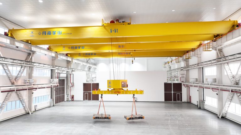
Henan Mine Crane · Aircraft Assembly, Tooling and Precision Component Handling
Aircraft Manufacturing Crane Systems
Engineered overhead, underhung, multi-point and workstation crane systems for fuselage sections, wings, engines, landing gear, composite molds, assembly fixtures and aircraft production maintenance.
Henan Mine Crane configures each aircraft manufacturing crane around the approved lifting points, load distribution, attachment, synchronization, positioning tolerance, production route, building interface, environmental controls and contracted acceptance criteria.
PRIMARY LOADS
Fuselage, Wings, Engines and Tooling
PLANT ZONES
Fabrication, Subassembly and Final Assembly
CRANE OPTIONS
Underhung, Bridge, Monorail or Workstation
CONTROL PRIORITIES
Synchronized, Low-Sway and Fine Positioning
What Is an Aircraft Manufacturing Crane?
An aircraft manufacturing crane is a lifting and positioning system engineered for sensitive, high-value aircraft structures and production equipment. Typical loads include fuselage barrels and panels, wing boxes, spars, empennage sections, engines, landing gear, composite molds, assembly jigs, machining fixtures and maintenance equipment.
Aircraft components are often long, thin-walled, asymmetrical and restricted to approved lifting or support points. Crane capacity alone does not establish suitability. The load path, force at every lifting point, center-of-gravity range, allowable deflection, surface protection, orientation, travel envelope and placement tolerance are defined before crane and attachment selection.
Available platforms include multi-support double-girder underhung cranes, double-girder bridge cranes, single-girder suspension cranes, monorails and project-specific synchronized lifting systems.
Aircraft Manufacturing Crane Applications
A single aircraft factory can require several lifting architectures. Heavy machining cells, composite production, subassembly bays, final assembly lines and maintenance areas have different loads, operating frequencies, floor-space constraints and acceptance criteria.
The crane schedule is therefore developed by production zone and load family rather than by applying one standard crane throughout the plant.
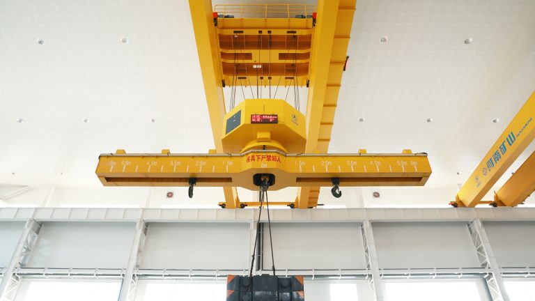
Composite and Machining Areas
Molds, fixtures, autoclave tooling, machined structures and raw materials require defined attachment interfaces, protected surfaces and clearance around production equipment.
Fuselage Subassembly
Panels, frames and barrel sections can require long spreaders, multiple hoists, rotation control and micro-speed alignment with jigs or adjoining structures.
Wing and Empennage Assembly
Long, flexible structures require approved support points, controlled load sharing, low sway and sufficient hook approach around assembly fixtures.
Final Assembly
Fuselage joining, wing installation, engine handling and system integration can use underhung networks or bridge cranes with synchronized hoists and protected work zones.
Tooling and Fixture Logistics
Assembly jigs, drill templates, access platforms and calibrated fixtures require repeatable transfer routes, safe parking positions and traceable lifting accessories.
Plant and Equipment Maintenance
Cranes can support robots, machine tools, ventilation equipment and process-line maintenance without assigning precision aircraft loads to a general maintenance crane.
Aircraft Crane System Architecture
| System Layer | Required Project Data | Typical Engineering Output |
|---|---|---|
| Aircraft Component | Mass, geometry, center of gravity, approved lifting points, allowable loads and surface limits | Load cases, point loads, orientation envelope and handling restrictions |
| Below-the-Hook Tooling | Spreader, sling, fixture, clamp, vacuum interface, adjustment and locking logic | Attachment design basis, deadweight, proof test and inspection plan |
| Hoists and Motion | Number of lifting points, load share, speeds, synchronization and positioning target | Hoist arrangement, feedback, micro-speed range, braking and control modes |
| Crane and Runway | Coverage, span, lift, hook approach, duty, building geometry and permitted reactions | Bridge or underhung layout, rail arrangement, wheel loads and clearances |
| Controls and Safety | Operating sequence, zones, interfaces, fault states, recovery and access rules | Functional description, interlock matrix, safety functions and acceptance tests |
| Production Integration | Station coordinates, takt requirements, plant network and quality records | Interface schedule, task flow, traceability and production acceptance plan |
Aircraft Manufacturing Crane Selection Considerations
Approved Load Interface
Aircraft engineering data defines lifting points, point-load limits, component stiffness, support direction, center-of-gravity range and prohibited contact areas.
Net Capacity at Every Point
Capacity includes the aircraft component, spreader, fixtures, slings and accessories. Individual hoists are checked for unequal load share and credible center-of-gravity positions.
Synchronization and Positioning
The specification states permissible height difference, skew, tilt, travel accuracy, repeatability, measurement point, load condition and acceptance method.
Production Duty
Lifts per shift, load spectrum, travel distance, loaded time, starts, inching, shifts and design life establish the crane and mechanism classification.
Building and Floor Access
Runway reactions, roof support points, deflection, headroom and floor obstructions determine whether a top-running, underhung or freestanding structure is practical.
Process Environment
Temperature, dust, composite fibers, clean-area requirements, paint or solvent operations, electromagnetic restrictions and washdown needs are documented by zone.
Aircraft Manufacturing Crane Configurations Compared
| Configuration | Typical Aircraft Duty | Primary Advantage | Main Engineering Check |
|---|---|---|---|
| Multi-Support Double-Girder Underhung Crane | Large assembly bays, fuselage sections, wings and broad production coverage | Clear floor with roof-supported, multi-rail load distribution | Roof reactions, support tolerance, equalization and runway alignment |
| Top-Running Double-Girder Bridge Crane | Heavy molds, major fixtures, engines and multi-hoist aircraft structures | High structural capacity and flexible trolley arrangements | Building columns, runway beams, hook approach and wheel loads |
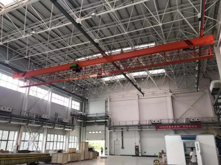
| Single-Girder Suspension Crane | Components, tooling and maintenance across compatible indoor bays | Low self-weight and unobstructed production floor | Capacity, span, roof support and available lifting height |
| Monorail with Synchronized Hoists | Repeat engine, fixture or component transfer on a fixed route | Defined path and repeatable station alignment | Route geometry, switch sections, load sharing and recovery |
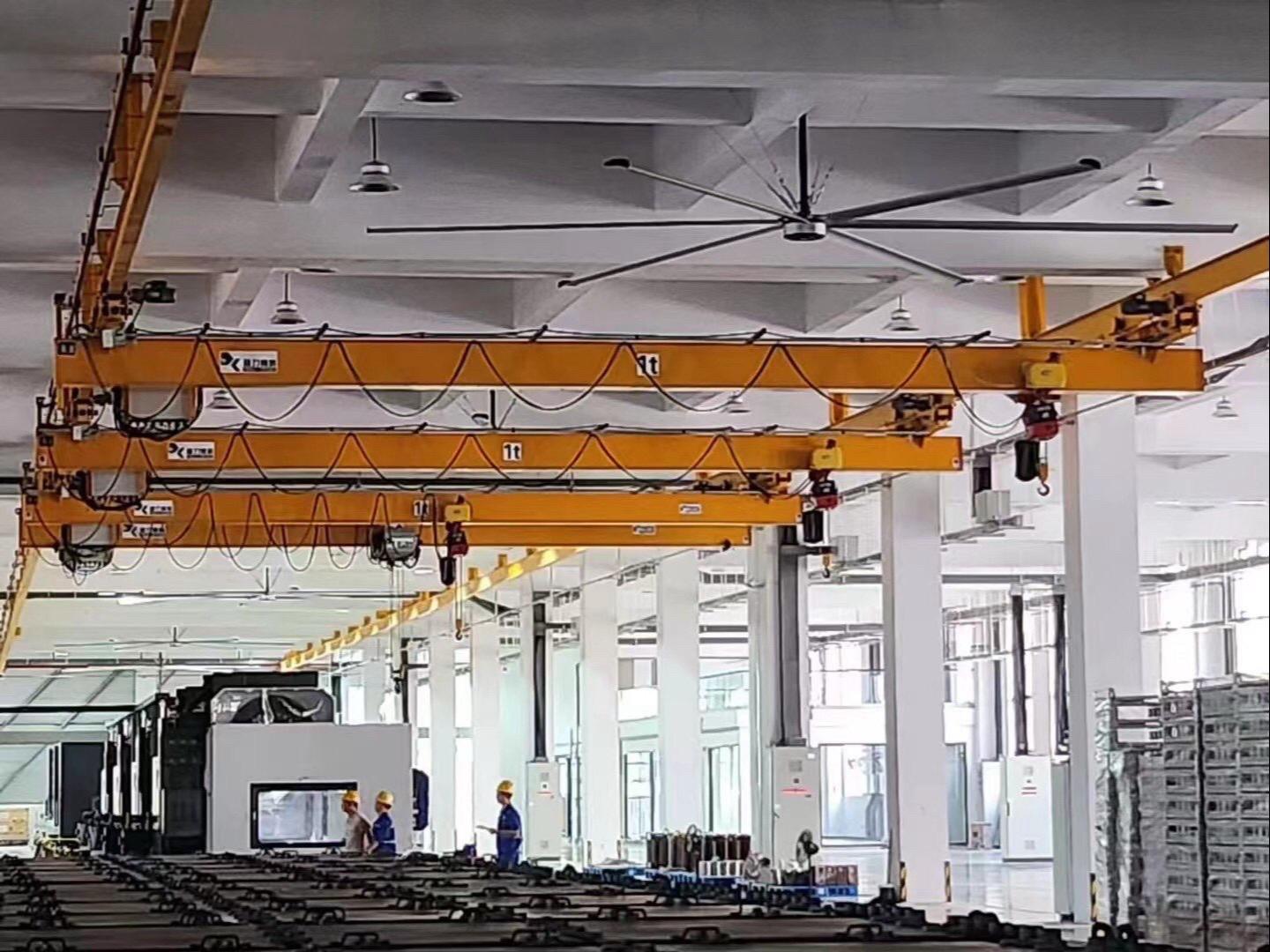
| Workstation or Light Crane System | Small assemblies, ergonomic tooling and point-of-use production support | Low moving mass and precise manual positioning | Coverage, support structure, load class and production interference |
| Freestanding Bridge or Semi-Gantry Crane | Localized cells, receiving areas and buildings without a suitable runway | Independent support and limited building modification | Foundation, column clearances, floor route and seismic or wind criteria |
Published Multi-Support Aircraft Crane Range
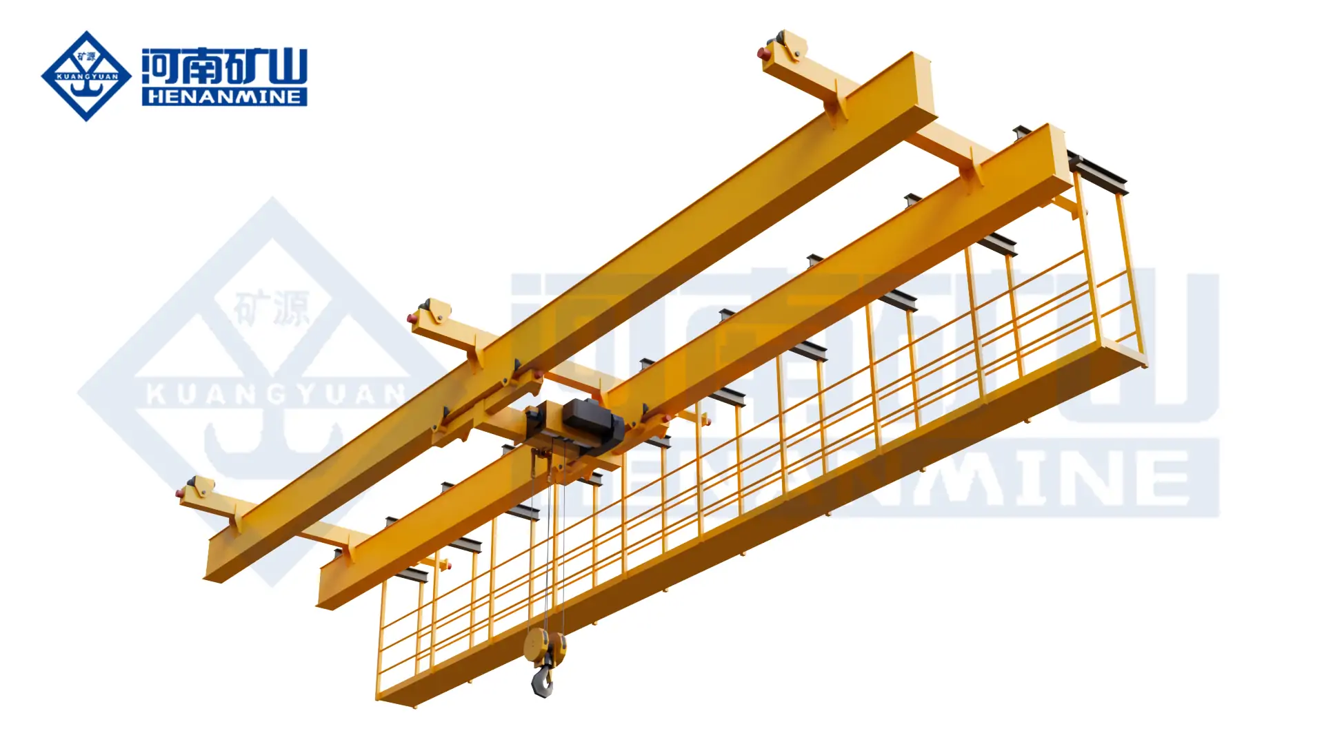
Henan Mine Crane publishes a multi-support double-girder underhung platform for aircraft manufacturing plants, maintenance hangars, aerospace assembly workshops and other large-span facilities. Multiple suspension points distribute the crane reactions across compatible roof or runway supports while keeping the production floor free of crane columns.
The platform can be configured with frequency-controlled lifting and travel, wireless or cabin control, multiple runway lines and project-specific attachments. Final capacity, span, speeds, duty, support reactions and control functions are selected from the approved aircraft process and building data.
| Published Parameter | Product Range | Project Selection Input |
|---|---|---|
| Rated Capacity | 3–40 t or customized | Component, attachment and governing point-load case |
| Crane Span | 10–80 m or customized | Bay width, runway lines, support spacing and deflection criteria |
| Lifting Height | 6–30 m or customized | Pickup elevation, assembly station and attachment depth |
| Working Class | A3–A5 or customized | Cycles, load spectrum, starts, travel and design life |
| Hoisting Speed | 0.5–16 m/min | Transfer speed, fine positioning and synchronization |
| Trolley Travel Speed | 2–20 m/min | Hook approach, sway control and station spacing |
| Crane Travel Speed | 5–60 m/min | Runway length, transfer cycle and protected speed zones |
| Power Supply | 220–690 V, 50/60 Hz | Plant voltage, frequency, earthing and permitted harmonics |
| Published Enclosure Level | IP54 | Dust, moisture, cleaning method and environmental classification |
Multi-Point Lifting for Fuselage, Wing and Engine Handling
Multi-point lifting is specified when the component cannot accept a concentrated single-point load or when orientation must be maintained during transfer. The number and position of lifting points follow aircraft or tooling engineering data rather than a generic formula.
Each hoist is rated for its maximum credible share of the load. Encoders, load monitoring or other feedback can supervise relative position and force. The control system coordinates lifting and lowering, limits differential movement and establishes a safe response to a drive, sensor, brake or communication fault.
Independent point adjustment may be included for final alignment. The permitted trim range, sequence, speed and authority are defined so that fine adjustment cannot create an unacceptable structural load.
Maximum and minimum force at every lifting point across all approved orientations.
Permissible relative height, tilt and travel difference under defined load and speed.
Controlled individual-point movement for docking, fitting and fixture alignment.
Safe stop, load retention, diagnosis and approved recovery without load instability.
Aircraft Crane Attachments and Load Protection
Custom Spreader Beam
Fixed or adjustable beams establish the required lifting-point spacing and sling direction. Beam deflection, deadweight, headroom and attachment parking are included.
OEM-Approved Lifting Fixture
A dedicated fixture can locate on defined hard points and control orientation. Mechanical locking, confirmation sensors and secondary retention follow the approved design basis.
Soft Slings and Surface Protection
Sling material, edge protection, contact pressure, cleanliness and replacement criteria are matched to coatings, composites and finished aircraft surfaces.
Powered Rotation or Tilting Fixture
Rotation and tilt support assembly or inspection where the component interface permits it. Speed, range, holding brake and unbalanced torque are specified.
Vacuum Lifting Device
Suitable panels require validated surface condition, curvature, porosity, seal geometry, reserve vacuum, alarms and a defined energy-loss response.
Engine and Landing-Gear Tooling
Purpose-built cradles and beams control center of gravity, clearance and installation orientation during removal, transfer and positioning.
Precision Motion, Anti-Sway and Production Controls
Motion Performance
Variable-frequency drives support smooth acceleration, deceleration and low-speed movement. Closed-loop feedback can be added where the contract defines positioning or synchronization performance. Brake selection covers normal stopping, holding, emergency states and load recovery.
Operating Modes
Pendant or wireless control supports direct operation. Assisted modes can add target zones, speed restrictions, anti-sway and alignment functions. Automatic modes require validated task data, station permissions, obstacle strategy and controlled manual recovery.
Plant Interfaces
Interfaces can include fixture-ready signals, station occupancy, access gates, production systems, load identification, position tracking, event records and maintenance data. Ownership of every signal and safe state is defined in the interface schedule.
Building, Runway and Clear-Floor Integration
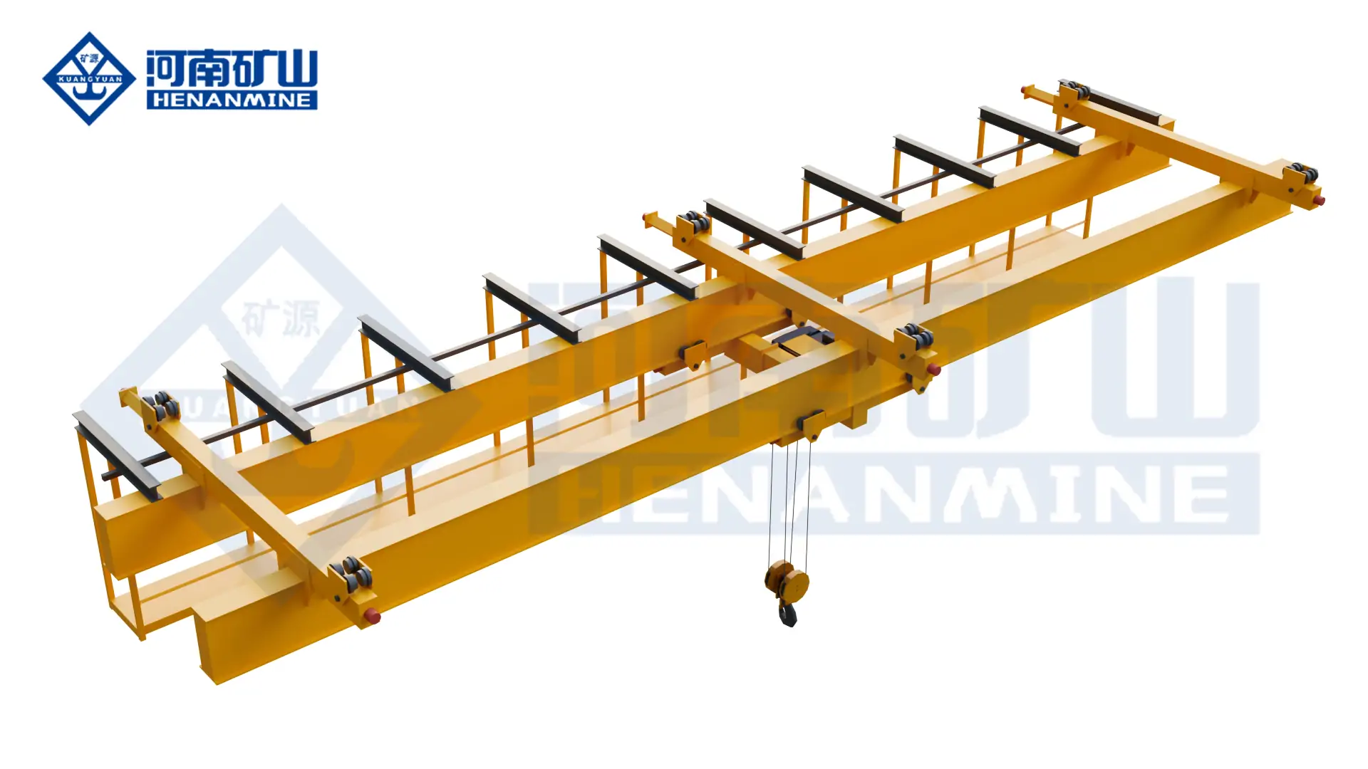
Aircraft assembly bays contain jigs, access platforms, automated equipment and wide component routes. Columns or floor rails can restrict production. Multi-support underhung systems distribute reactions across several roof or runway lines and maintain an open production floor.
The structural assessment covers maximum and minimum vertical reactions, lateral and longitudinal forces, buffer loads, simultaneous crane positions, runway or roof deflection, connection forces, tolerances, fatigue, seismic criteria and erection loads.
Existing buildings require a condition survey and verified drawings. New buildings require coordinated crane loads before the steelwork is finalized. Crane geometry, electrification, maintenance access, fire systems, lighting, ducts and overhead process services are resolved in the coordinated layout.
Clean Areas, Composite Production and Hazardous Zones
Controlled Clean Area
Particle-control measures can include enclosed drives, compatible coatings, controlled lubrication, protected festoons, cleanable surfaces and a maintenance plan aligned with the declared room classification.
Composite Dust and Fibers
Composite machining or trimming areas require an environmental assessment covering conductive fibers, enclosure protection, cooling, cleaning access and electrical equipment exposure.
Paint and Solvent Areas
Explosion-protected equipment is selected only from the approved hazardous-area classification, gas or vapor group, temperature class, zone, ambient range and required conformity route.
A general aircraft assembly hall does not automatically require cleanroom or explosion-proof construction. Each production zone is assessed separately so that electrical protection, materials and maintenance controls match the actual environment.
Where a classified hazardous area is confirmed, the crane package can require protected motors, brakes, controls, limit devices, cable systems, enclosures and operating procedures compatible with the governing explosion-protection framework.
Safety, Standards and Acceptance Testing
The purchase specification identifies the destination regulations and the selected design framework. Common references can include ISO 4301-1 for crane classification, ISO 9927 for inspection, ASME B30.2 for applicable top-running cranes, ASME B30.17 for applicable underhung cranes and monorails, and IEC 60079 where explosion-protected equipment is required.
Core Protective Functions
Overload and overtravel protection, motion limits, emergency stop, brake monitoring where specified, anti-collision, restricted zones, alarm states and safe isolation.
Factory Acceptance Test
Document review, mechanism operation, controls, alarms, interfaces, load or simulated-load testing, synchronization, positioning, abnormal states and recovery sequences.
Site Acceptance Test
Runway geometry, electrification, rated and proof loads, station access, representative tooling, interfaces, accuracy, production sequence, training and handover records.
Production Acceptance
Approved representative loads verify attachment engagement, point-load behavior, synchronization, component clearance, placement, cycle and controlled exception handling.
Documentation
Approved drawings, calculations as contracted, certificates, electrical diagrams, software backups, test records, manuals, inspection plans, spare-parts data and training records.
Lifecycle Control
Scheduled inspection, attachment records, calibration where required, brake and rope monitoring, lubrication, critical spares, change control and operating-data review.
Published Aerospace Precision-Handling Project
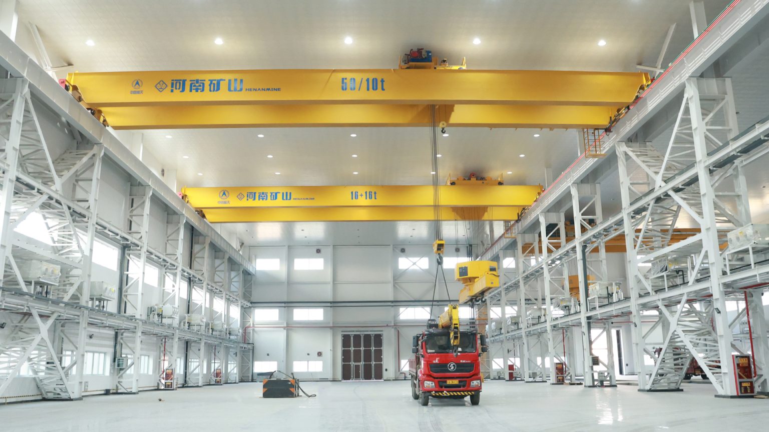
24 Equipment Sets Delivered to an Aerospace Research Institute
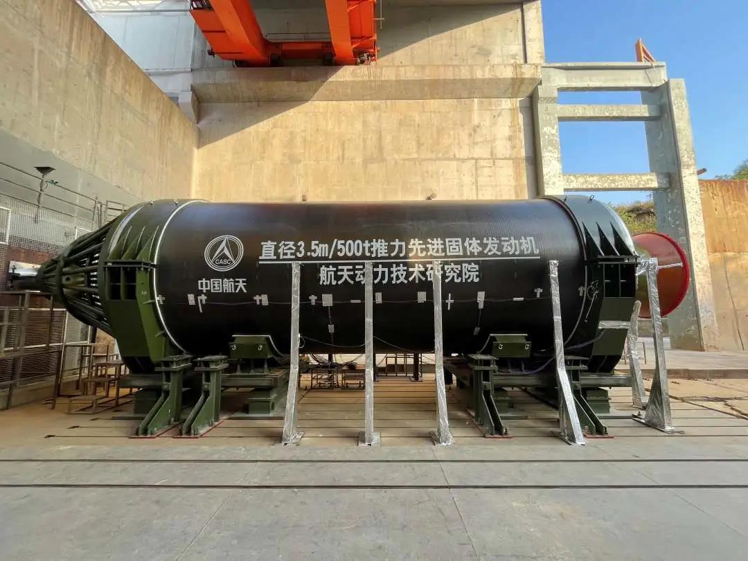
Henan Mine Crane reports delivering 24 equipment sets to a space research institute, including six lower-rotating girder bridge cranes placed into operation. The published application covers precision transfer of aerospace power components and structural parts.
The published crane platform combines PLC and inverter closed-loop vector control, remote, manual and tablet operating modes, a servo-controlled attachment with extension and rotation, personnel and obstacle detection, and remote equipment monitoring.
The delivery passed acceptance by the Xi’an Institute of Special Equipment Inspection and Testing. The operating data and performance requirements for a new aircraft manufacturing project are established from its own components, plant layout and acceptance plan.
Aircraft Manufacturing Crane Price and Budget Scope
Aircraft crane pricing depends on the crane structure, number of lifting points, attachment, synchronization, control accuracy, building interface, environmental package, installation and acceptance scope. Public prices reviewed in 2026 show the difference between a component kit and a complete support system; aerospace-specific systems require a project quotation.
| Public Market Reference | Published Price | Supply Level | Scope Included or Excluded |
|---|---|---|---|
| 5 t Overhead Crane Kit with Hoist | US$23,250 | North American component kit listing | End trucks, controls, festoon and hoist; bridge steel, paint, fabrication tools and labor are excluded |
| 2 t One-Cell Freestanding Bridge System | US$61,102.95–66,655.15 | Complete listed system with hoist | Published range varies with 20–30 ft runway; aircraft tooling, local erection and production interfaces are separate |
| 7.5 t Two-Cell Freestanding Bridge System | US$94,750.80 | Specific 20 ft × 40 ft-per-cell retail system | A fixed commercial configuration; aircraft attachment, synchronization and plant acceptance are not included |
| Aircraft Underhung or Multi-Point Crane | Project-specific RFQ | Crane, synchronized hoists, attachment and controls | Price follows the aircraft load matrix, roof or runway design, accuracy, interfaces, destination and contracted services |
| Automated, Clean or Explosion-Protected System | Project-specific RFQ | Engineered process system | Requires functional specification, environmental classification, safety design and acceptance matrix |
Main Cost Drivers
Capacity, span, lift, support arrangement, duty, wheel or roof reactions and access.
Number of hoists, load monitoring, synchronization, micro-speed and braking architecture.
Spreader, fixtures, powered axes, surface protection, sensors, stands and proof testing.
Freight, erection, commissioning, calibration, representative-load tests, training and warranty.
Engineering and Procurement Deliverables
Design Basis
Load families, approved lifting points, attachment, crane classification, motions, accuracy, environment, standards and exclusions.
General Arrangement
Plan, elevation, hook approaches, clearances, support positions, maintenance access, electrification and maximum reactions.
Attachment Package
Rated point loads, deadweight, engagement, locking, powered motions, proof test, inspection criteria and storage stand.
Control Description
Operating modes, synchronization, speed zones, interlocks, alarms, communications, fault handling and manual recovery.
Inspection and Test Plan
Material and manufacturing records, mechanism tests, load tests, accuracy checks, interface tests and document hold points.
Commercial Schedule
Price, Incoterm, milestones, delivery, erection, commissioning, acceptance, documentation, training, spares, warranty and exclusions.
Aircraft Manufacturing Crane RFQ Information
A configuration-based proposal requires the following project data.
Aircraft Load Matrix
Component names, mass, dimensions, center-of-gravity range, approved lifting points, allowable point loads, orientation and drawings.
Handling Sequence
Pickup and destination stations, route, required orientation, lift frequency, shifts, cycle, dwell, alignment steps and contingency.
Building and Layout
Span, lift, runway length, support layout, allowable reactions, building drawings, obstructions, installation access and power supply.
Controls and Environment
Synchronization, positioning, operating modes, plant interfaces, safety zones, clean-area or hazardous classification and ambient conditions.
Standards and Acceptance
Destination regulations, design standards, conformity route, FAT, SAT, representative loads, accuracy tests, documentation and training.
Commercial Boundary
Destination, Incoterm, runway or roof steel, freight, duties, erection, commissioning, test loads, spares, warranty and schedule.
Frequently Asked Questions
Which crane is suitable for aircraft final assembly?
Large final-assembly bays commonly use multi-support underhung systems or bridge cranes with multiple synchronized hoists. The building, component load path, required coverage and positioning criteria determine the configuration.
Why are multiple lifting points used?
Multiple points distribute force across approved interfaces and stabilize long or flexible components. Point quantity and spacing follow aircraft structural and tooling data.
How is aircraft crane capacity calculated?
The rated requirement includes the component, spreader, fixtures, slings and accessories. Every hoist and structural element is checked for the governing load share, center of gravity and operating case.
Can an aircraft crane operate automatically?
Automatic or assisted operation can include target positions, synchronized motion, anti-sway, protected zones and plant interfaces. The operating sequence, exceptions and manual recovery are validated before production release.
Does every aircraft plant require an explosion-proof crane?
No. Explosion-protected construction is required only where the approved hazardous-area classification establishes the applicable zone, material group, temperature class and equipment protection requirements.
Can an existing hangar roof support an underhung crane?
Only after the roof framing, connections, foundations, condition, fatigue history, allowable reactions and deflection are verified for every crane and load position.
How much does an aircraft manufacturing crane cost?
Published standard-system prices are not valid for an aircraft project without the load interface, number of lifting points, span, structure, accuracy, controls, environment, installation and acceptance scope.
What should be tested with representative aircraft tooling?
Tests can verify engagement, point loads, synchronization, clearance, micro-speed, position, interlocks, abnormal stopping, restart and the approved handling sequence.
Related Aircraft Manufacturing Crane Products
Select the crane platform according to the aircraft component, lifting-point arrangement, plant coverage, building support, duty, positioning and environmental requirements.
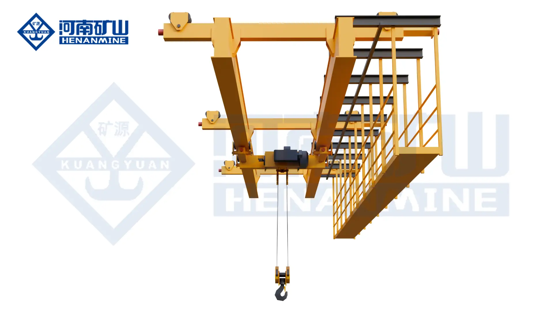
Multi-Support Double-Girder Underhung Crane
Roof-supported large-span platform for unobstructed aircraft assembly and component transfer.
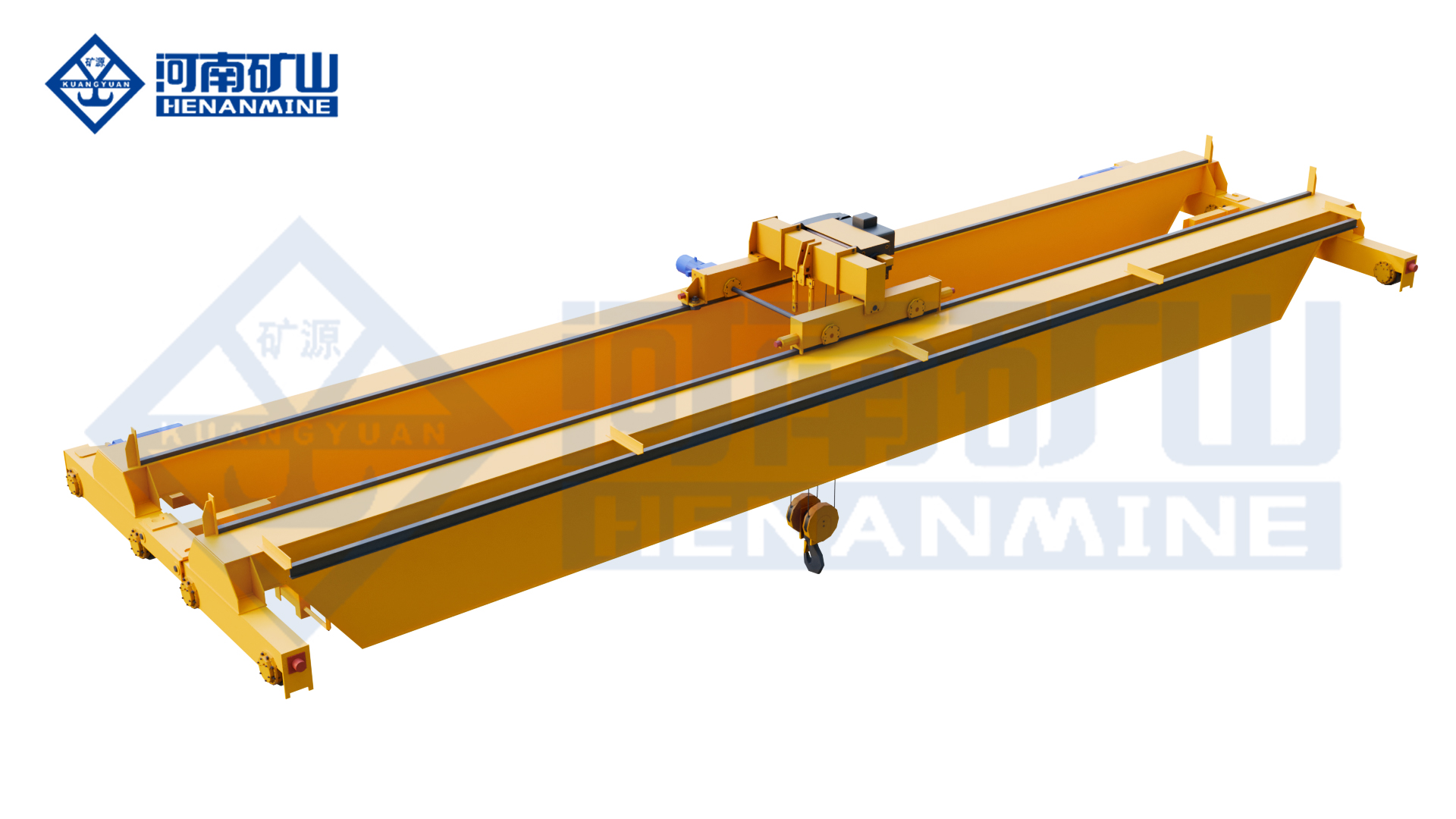
Double-Girder Bridge Crane
Configurable platform for heavy molds, fixtures, engines and multi-hoist lifting duties.
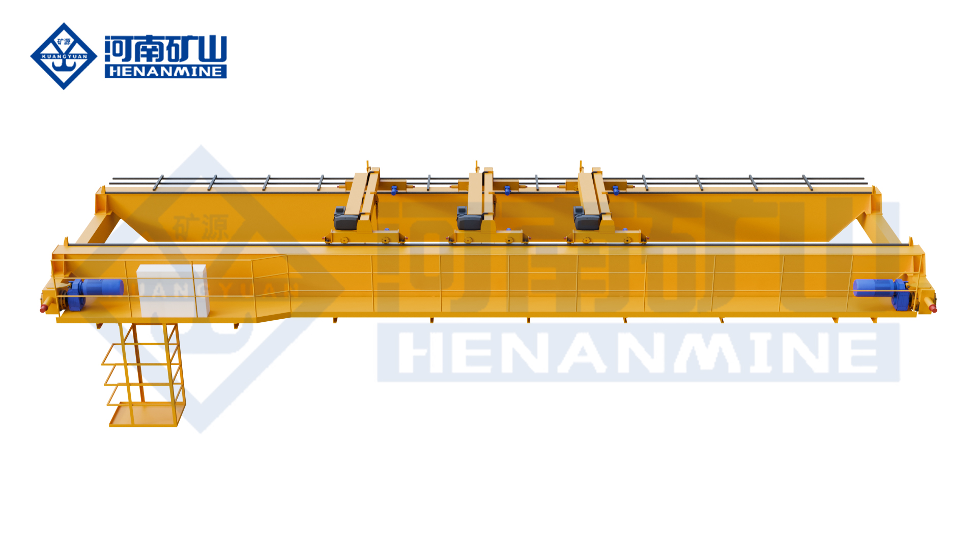
Single-Girder Suspension Crane
Underhung coverage for component, tooling and maintenance work with a clear floor.
Intelligent Electric-Hoist Crane
Low-headroom platform with controlled motion and digital monitoring options.
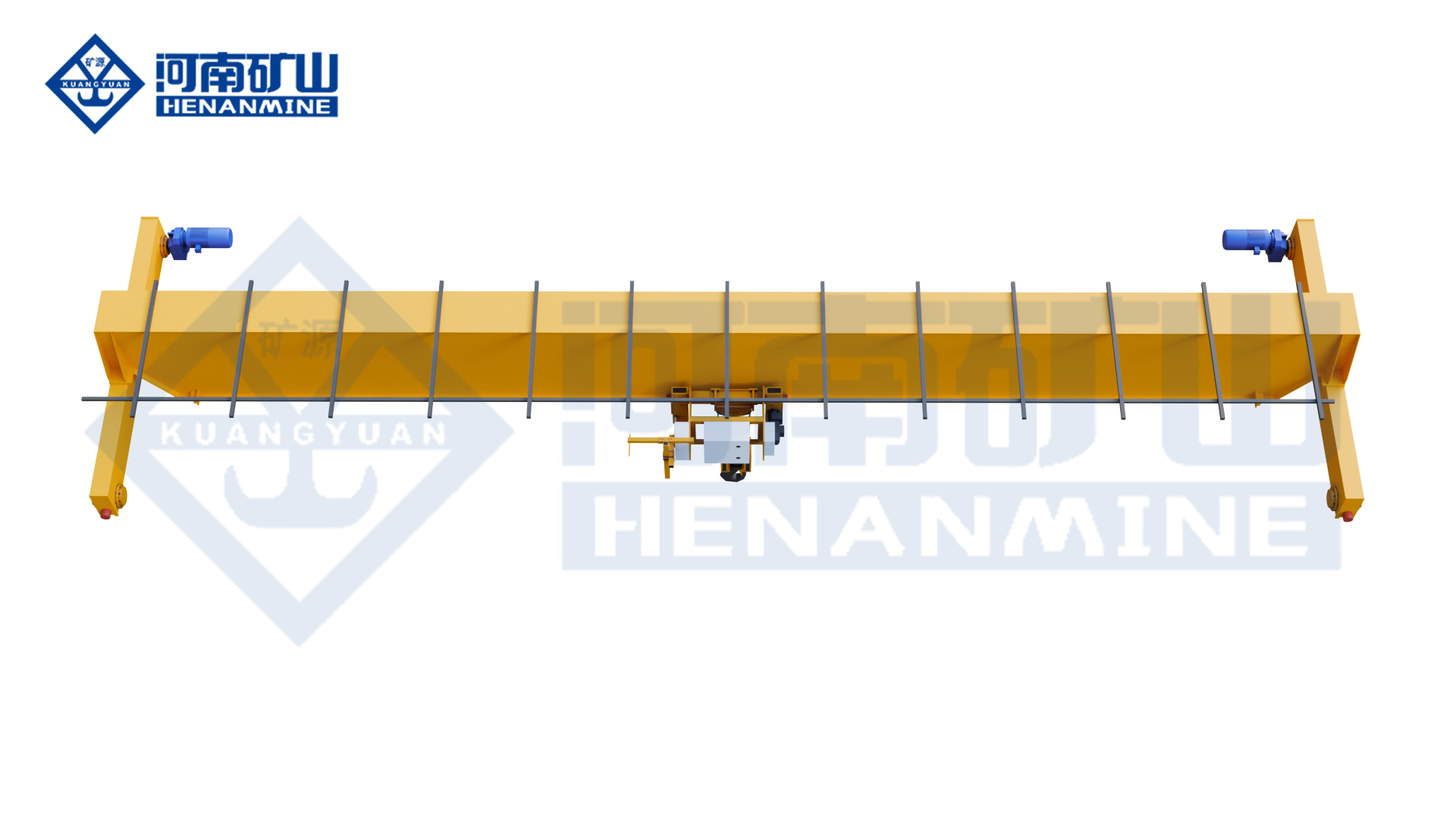
European-Style Single-Girder Crane
Compact general-purpose crane for parts, tooling, warehouses and line support.
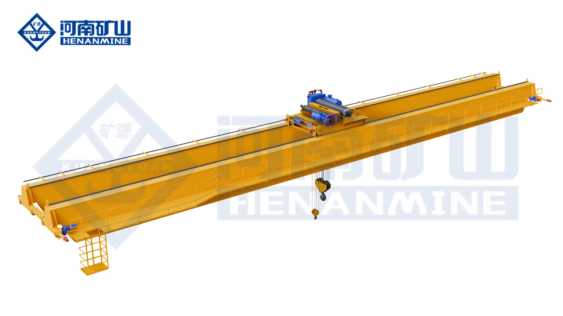
Explosion-Proof Overhead Crane
Protected crane configuration for an approved hazardous-area classification.
Technical review: Henan Mine Crane Engineering
Last reviewed: 2026
Request an Aircraft Manufacturing Crane Quote
Submit the aircraft component matrix, approved lifting points, load distribution, attachment concept, handling route, synchronization and positioning requirements, span, lift, building data, operating environment, control interfaces, destination and supply boundary. Henan Mine Crane will prepare a configuration-based technical and commercial proposal.