Engineering · Manufacturing · Project support
info@hnksglobal.comWhatsApp +86 18836207779 ↗

Blog

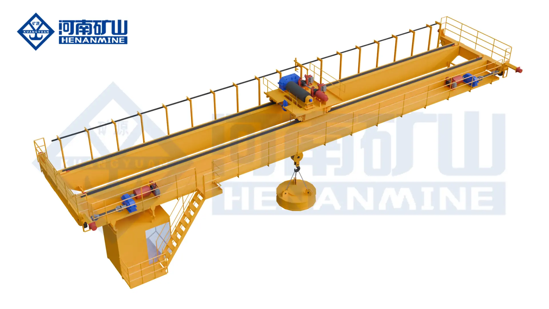
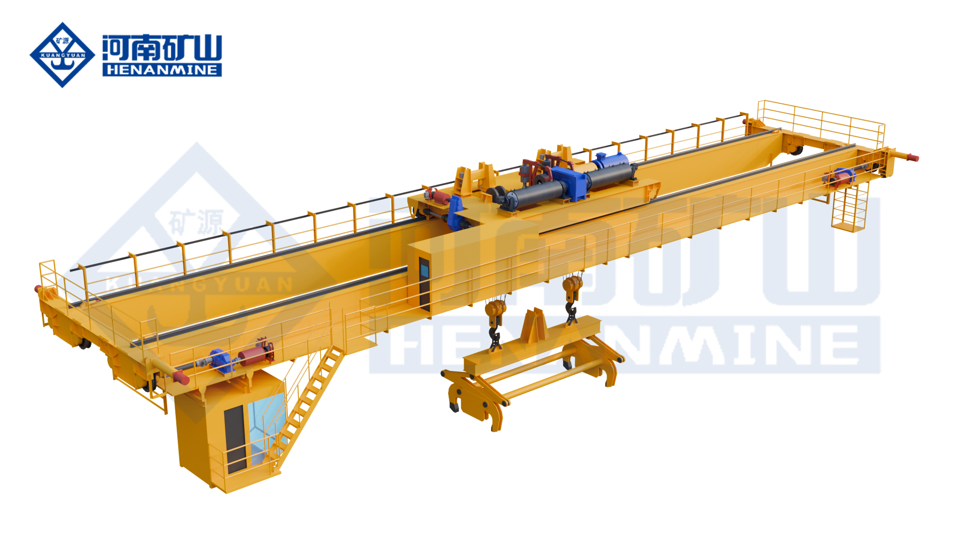
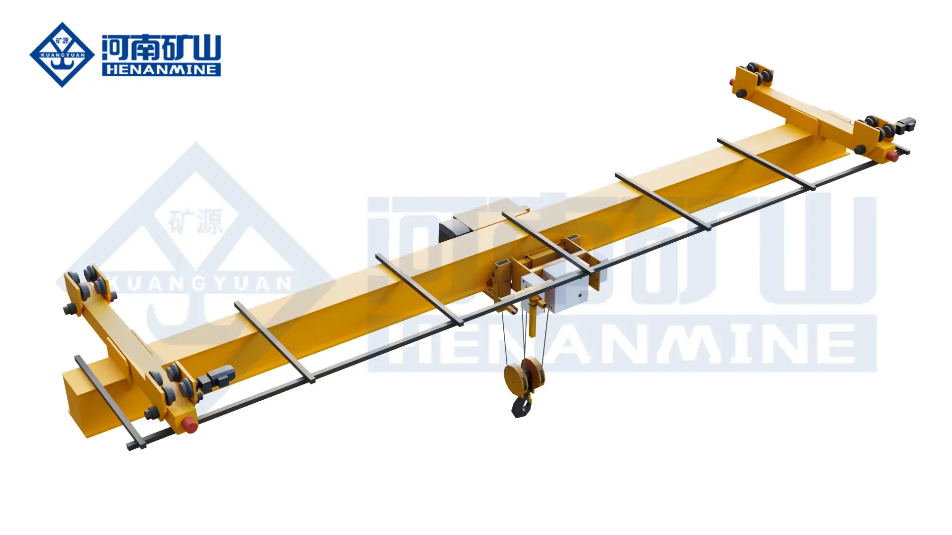
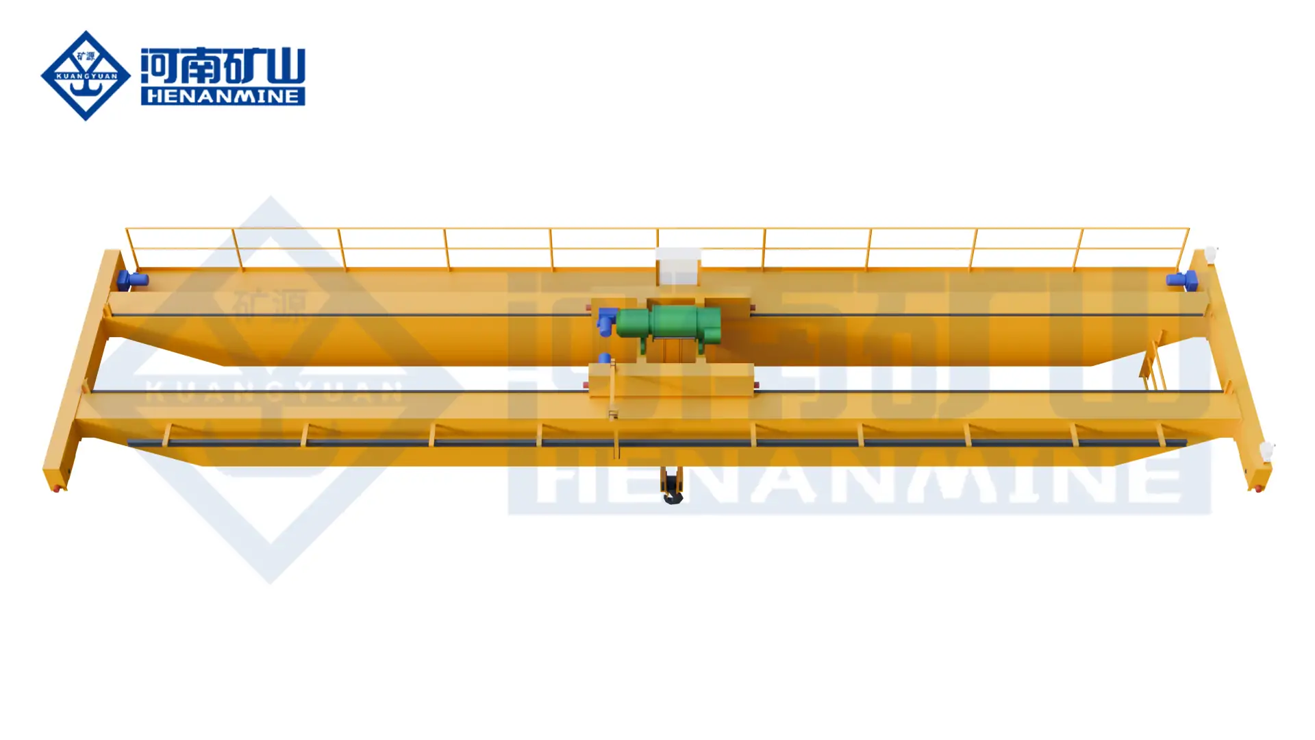
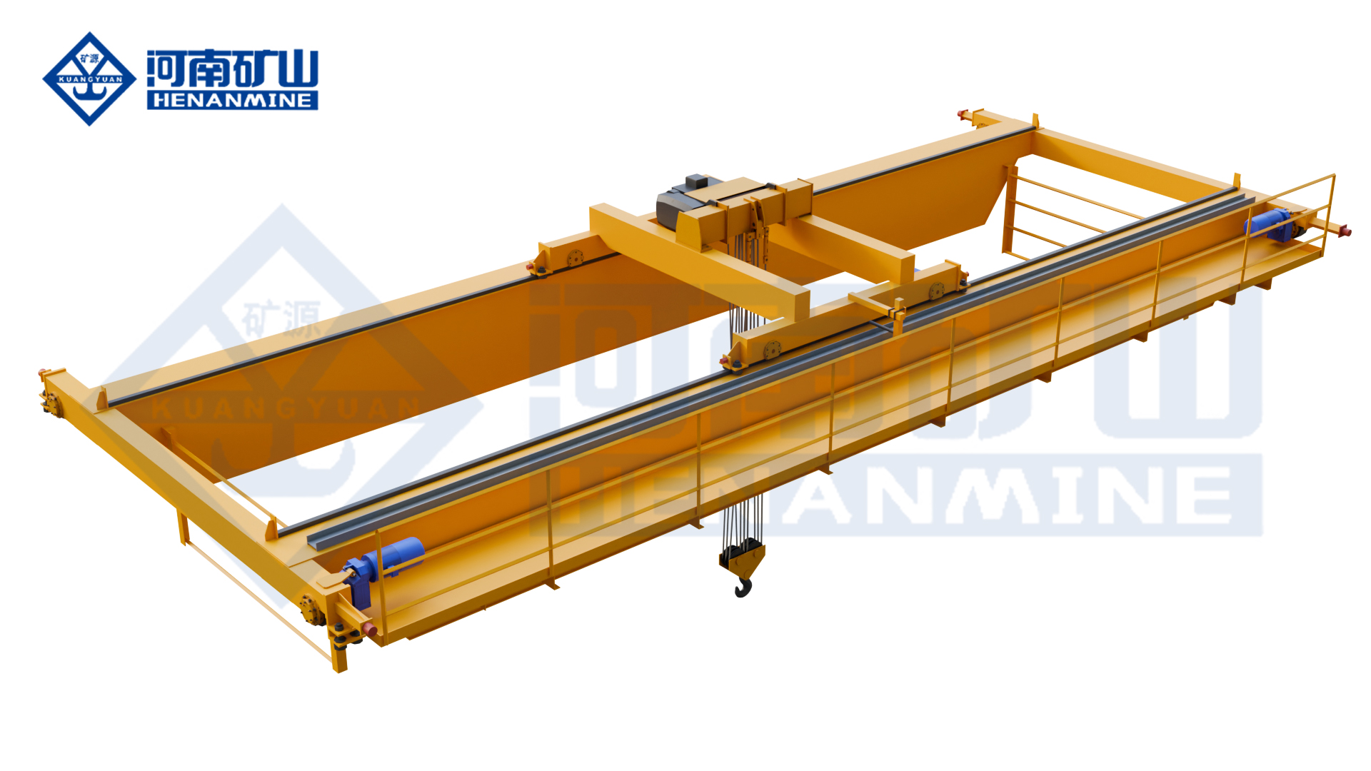
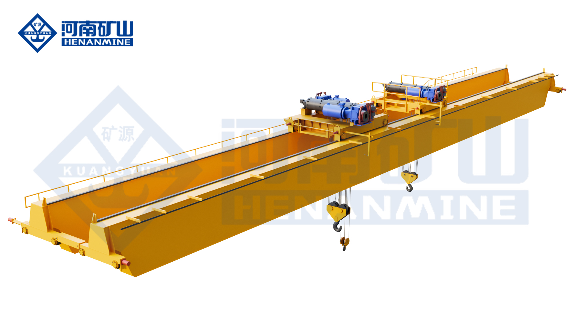
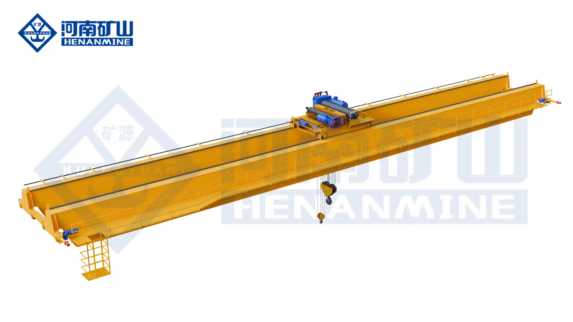
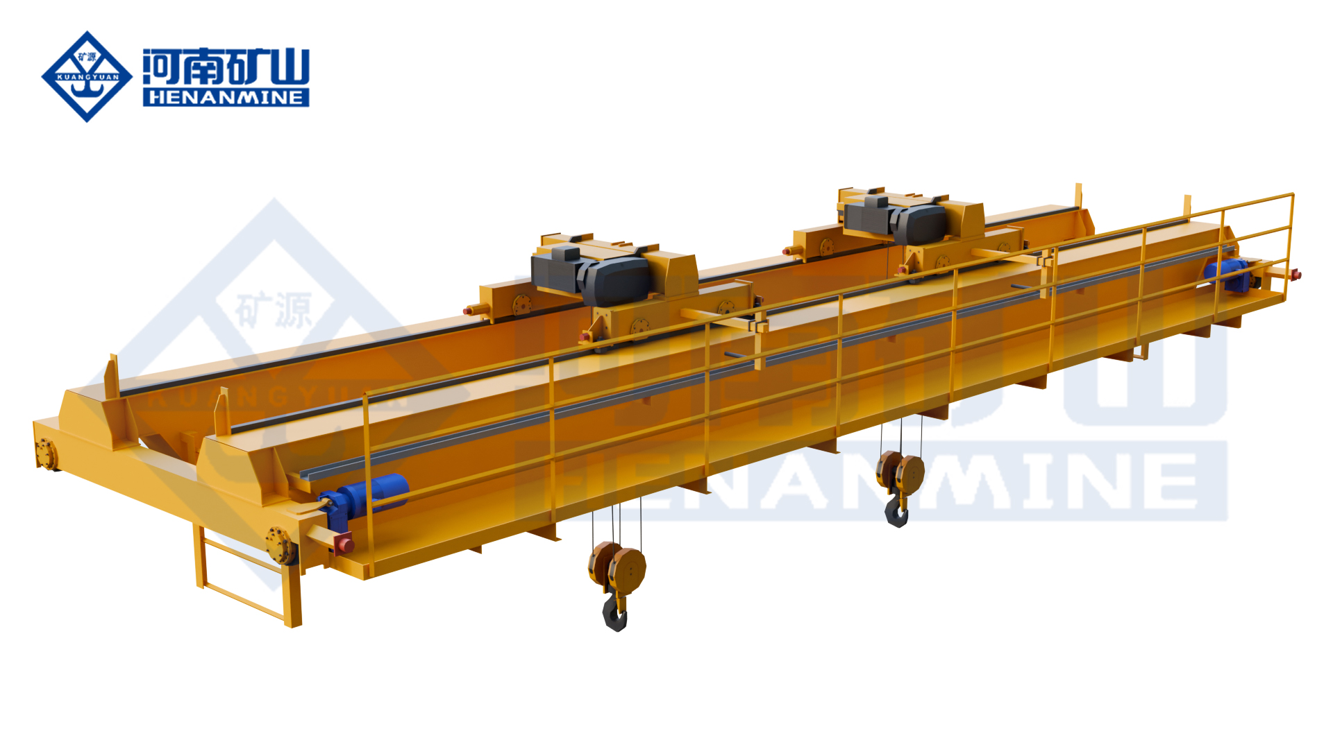
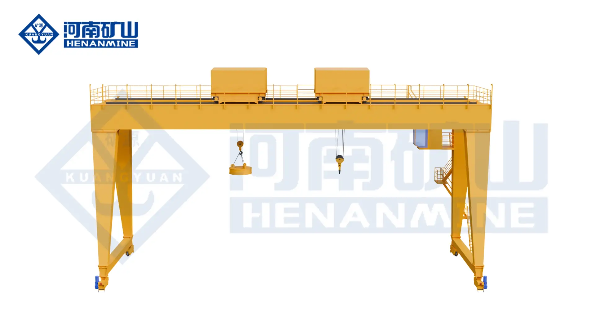
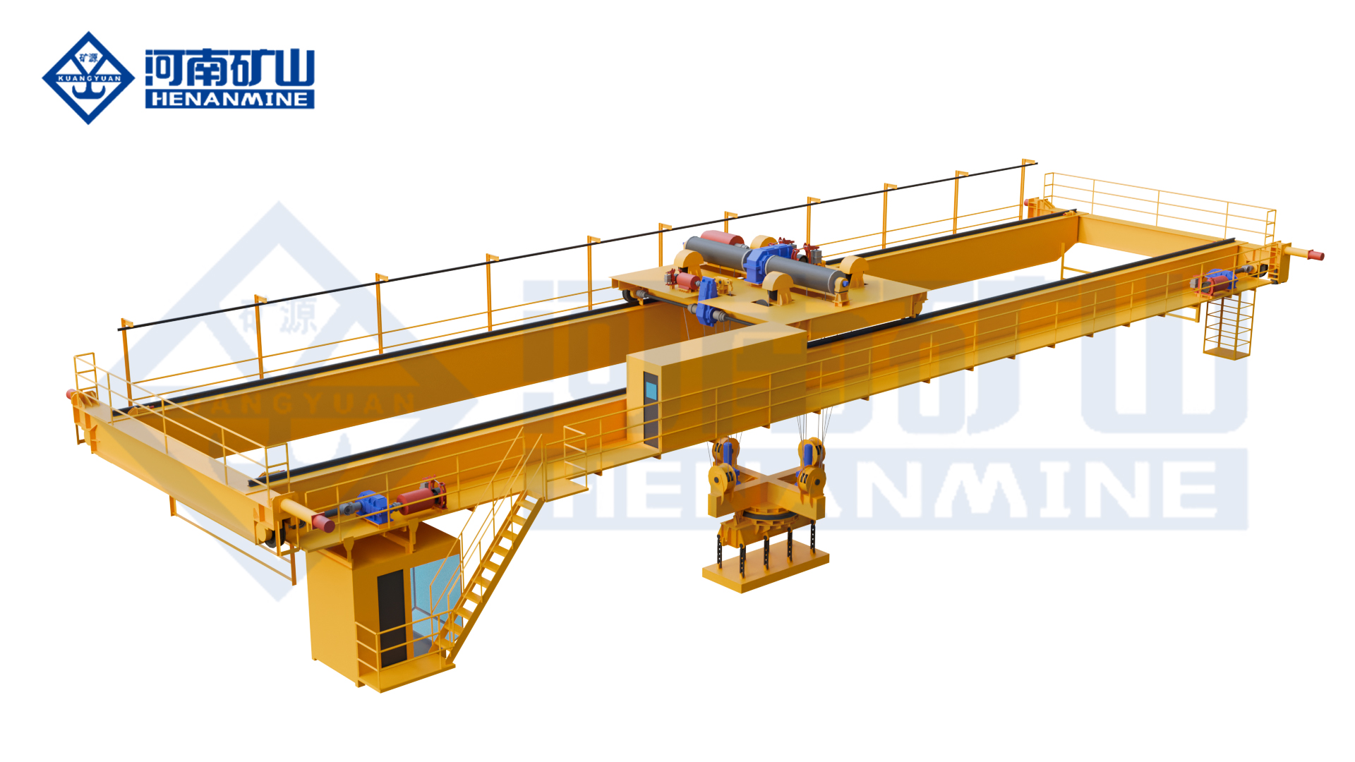
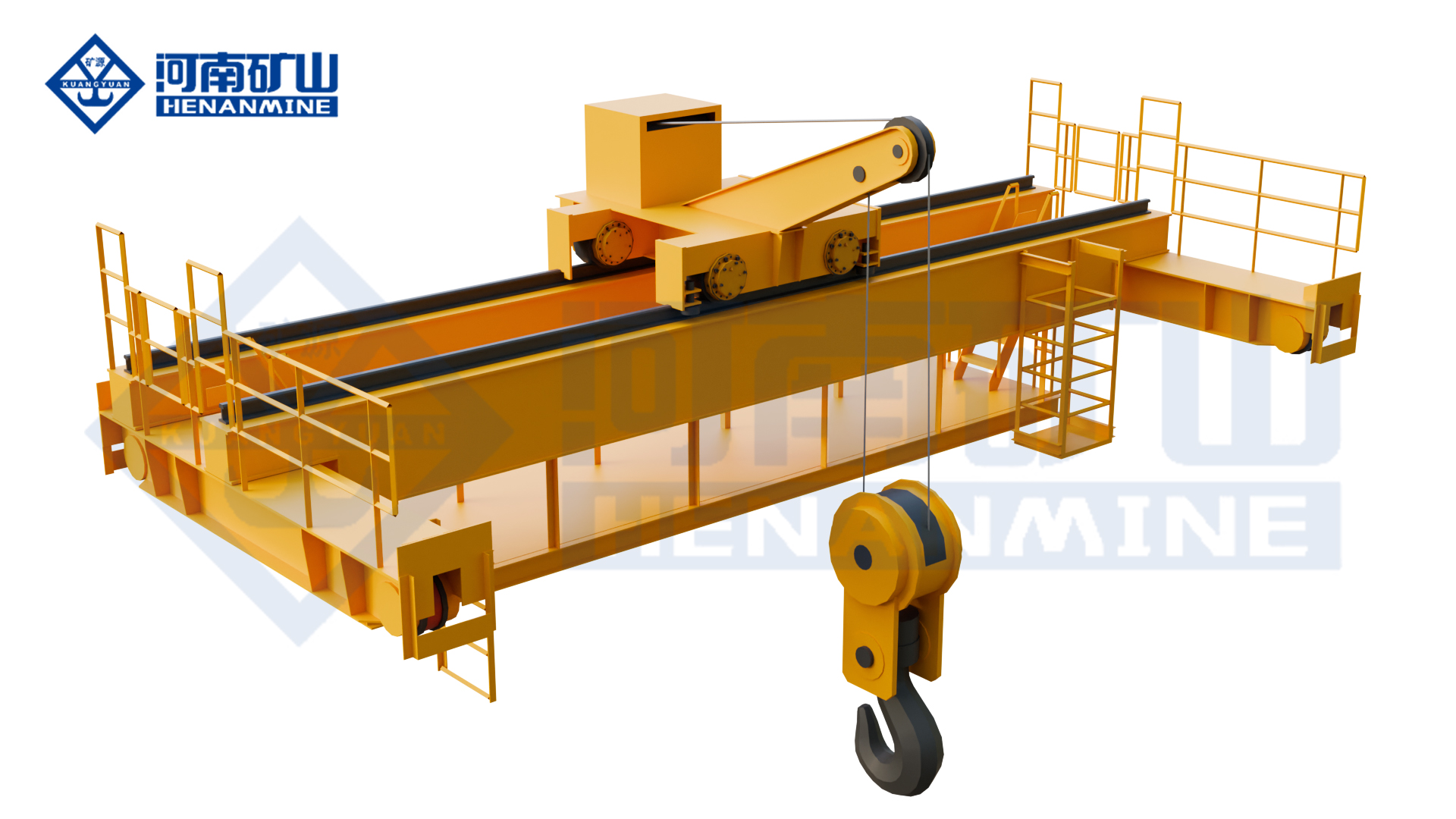
  • Electromagnetic Hanging Beam Crane

    Electromagnetic Hanging Beam Crane

    Overhead Cranes / Henan Mine Crane

    Electromagnetic Hanging Beam Crane

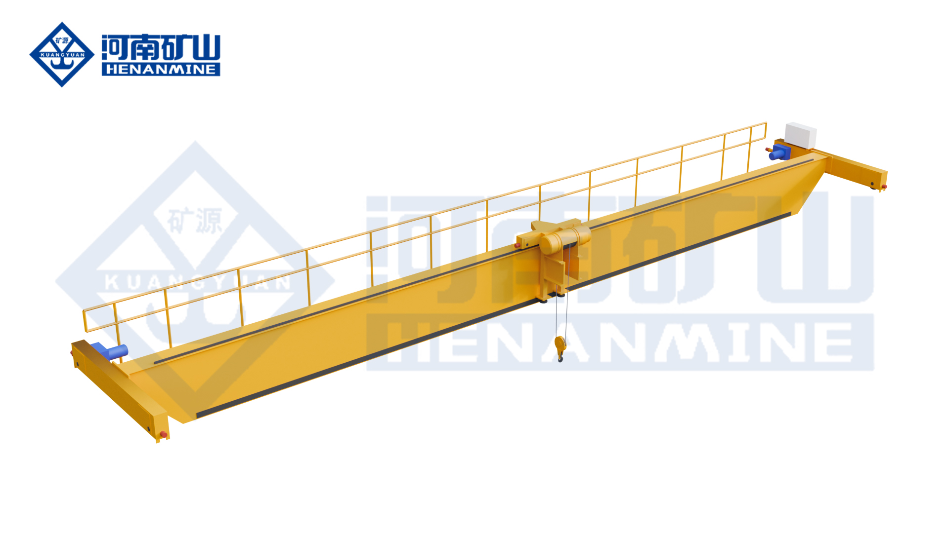
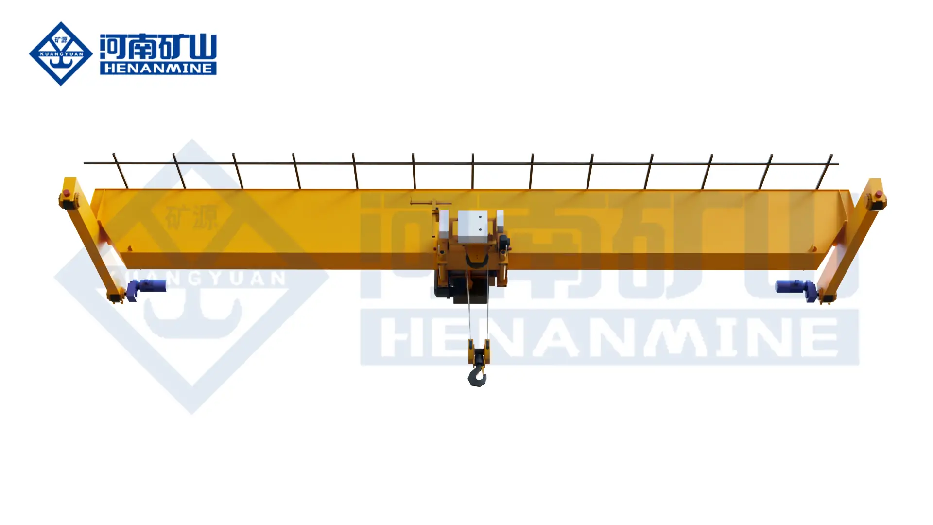
    Support long steel products with an electromagnetic hanging beam. Beam length, magnet spacing and lifting points are configured around product geometry, orientation and stacking requirements.

    Lifting capacity5 – 50 t
    Span10.5 – 31.5 m
    Working classA6 – A7
    Technical specifications

    Define the total suspended load, duty and site conditions for your project.

    Technical specifications

    Check the load.
    Plan the configuration.

    Parameters and equipment options are matched to the application and confirmed in the technical proposal.

    Discuss your configuration
    Capacity5 – 50 t
    Span10.5 – 31.5 m
    Lifting height6 – 20 m
    Working classA6 – A7
    Crane travel15-30m/min
    Power supply220-690V, 50/60Hz
    ControlsWireless Remote / Cabin Control

    Final parameters, dimensions, wheel loads and supply scope follow the approved project specification.

    Application & operation

    Matched to the handling task.

    Long steel products

    Coordinate several pickup positions along plates, sections or other suitable steel products.

    Steel storage bays

    Match the lifting beam and magnet layout to pickup and stacking positions.

    Selection considerations

    Start with your operating conditions.

    01

    Load & lifting arrangement

    Specify product length, section, temperature and weight distribution. Include lifting-appliance weight and the required lifting positions.

    02

    Site & available space

    Provide beam clearance, stacking orientation and available hook height. Coordinate the installation interfaces with the available site drawings.

    03

    Duty & control sequence

    Define magnet spacing, lifting cycle and power-loss response. Identify the required movements and control interfaces in the enquiry.

    Configuration comparison

    Compare related lifting arrangements.

    Crane arrangementHandling configuration
    Electromagnetic Hanging Beam CraneSupport long steel products with an electromagnetic hanging beam. Beam length, magnet spacing and lifting points are configured around product geometry, orientation and stacking requirements.
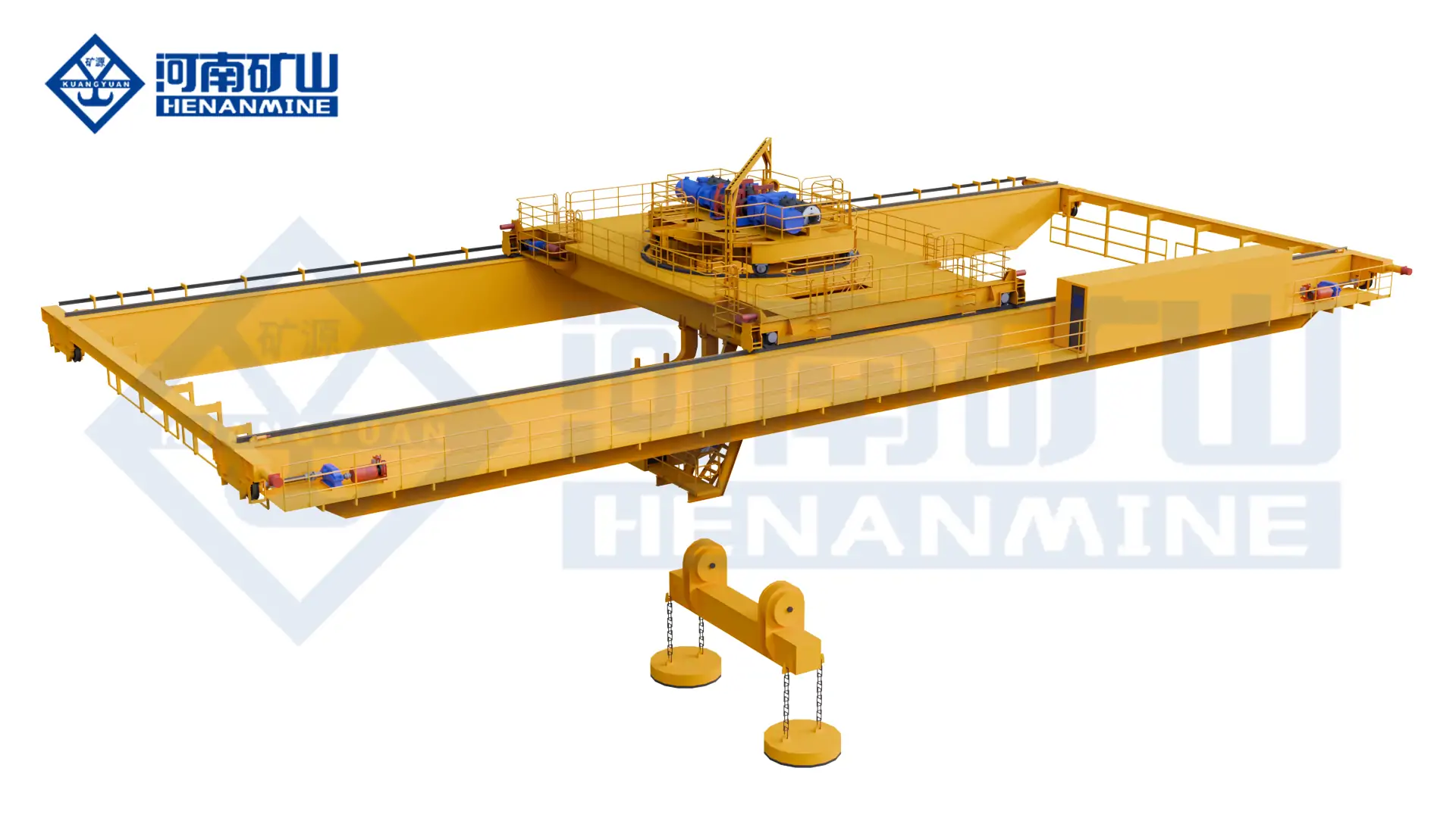
    Upper Rotating Magnetic Overhead CraneA rotating magnetic beam for positioning long steel products. Magnet arrangement, material temperature and power-loss protection require a matched specification.
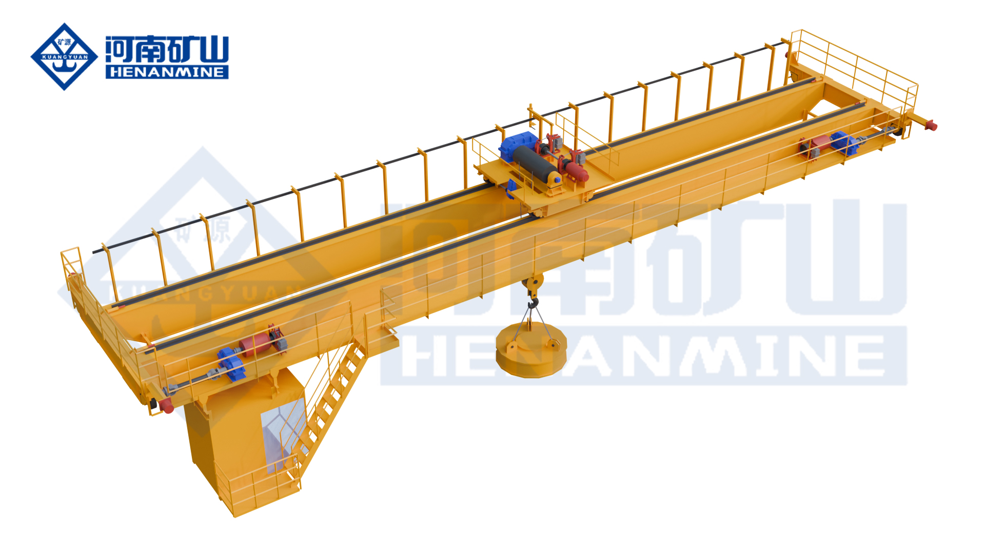
    Electromagnetic Overhead CraneLift ferromagnetic steel with a matched electromagnetic lifting arrangement. Product shape, contact area, temperature and handling frequency determine the magnet and crane configuration.
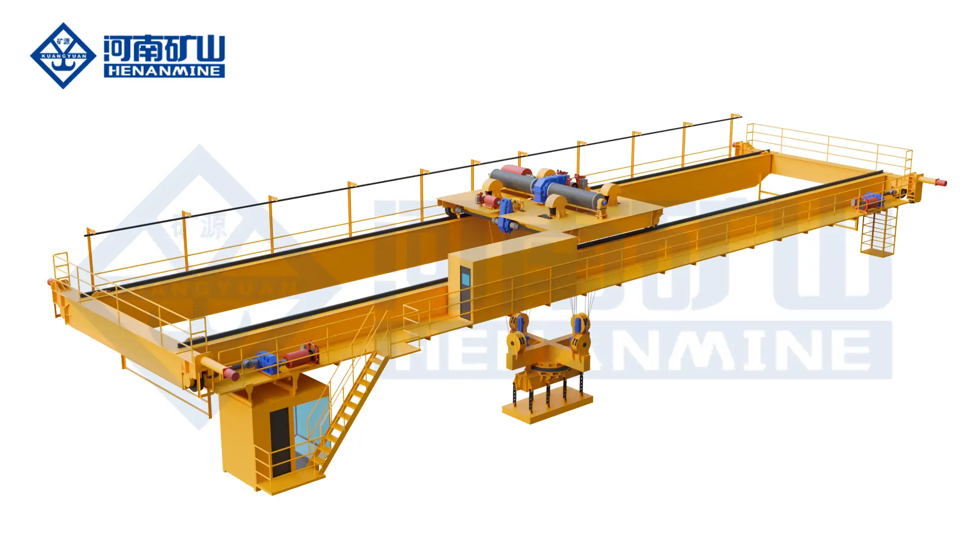
    Slab Handling CraneTransfer and stack steel slabs with a crane matched to slab geometry, temperature and the lifting appliance. Coordinate pickup conditions, stacking orientation and the production cycle.

    Operating protection & lifecycle support

    Plan beyond the equipment.

    01

    Operating protection

    Confirm overload protection, travel limits, brakes, emergency controls and the required process interlocks for the declared lifting task.

    02

    Installation & commissioning

    Agree runway reactions, structural interfaces, electrical connections, assembly, inspection and commissioning responsibilities before delivery.

    03

    Inspection & spares

    Plan inspection and maintenance of beam connections, suspension points and magnet cable routing. Agree service access, documentation and the required spare-parts scope.

    Questions before the order

    Clarify the details
    that shape the crane.

    What information is needed for a electromagnetic hanging beam crane quotation?+

    Provide product length, section, temperature and weight distribution; beam clearance, stacking orientation and available hook height; and magnet spacing, lifting cycle and power-loss response. Include drawings and the project destination when available.

    How is magnet spacing on the beam determined?+

    Provide the product geometry, support requirements and possible pickup conditions. Beam and magnet positions are selected so the proposed lifting arrangement can handle the declared product range.

    What installation and support scope should be agreed?+

    Agree runway reactions, structural interfaces, electrical connections, assembly, inspection and commissioning responsibilities before delivery. Specify the documentation, training and spare-parts support needed for the project.

    Related equipment

    Explore the alternatives.
    Let’s discuss your project

    The right crane starts
    with your lifting task.

    Share product length, section, temperature and weight distribution, together with your site layout and operating cycle.
    info@hnksglobal.com
  • Oil and Gas Facility Cranes in Kuwait: Process and Site Requirements

    Oil and Gas Facility Cranes in Kuwait: Process and Site Requirements

    Technical guide

    Oil and Gas Facility Cranes in Kuwait: Process and Site Requirements

    An equipment brief should identify the lifting task and applicable site conditions at the actual facility. Coordinate area information, environmental inputs and installation responsibilities before developing the crane proposal.

    Henan Mine CraneTechnical guide · Updated 2026Crane selection, project scope and operating requirements
    Henan Mine Crane Galvanizing Process Overhead Crane
    Henan Mine Crane Galvanizing Process Overhead Crane
    Project planning notes

    Key points for this crane project.

    1. Understanding Kuwait's Oil & Gas Infrastructure
    2. Key Crane Requirements for Oil & Gas Projects in
    3. Types of Cranes Commonly Used in Kuwait's Oil & Gas
    Read the technical guide

    Understanding Kuwait's Oil & Gas Infrastructure

    Kuwait's oil and gas industry is coordinated and operated by the state-owned KPC, which was established in 1980, with a clear division of labor among its subsidiaries and a complete industrial system, and all the oil and gas lifting standards and safety norms are uniformly formulated and enforced by KPC.

    Industry Core Management Structure

    KPC's core subsidiaries cover the whole oil and gas industry chain:

    • KOC: the core upstream company, responsible for onshore oil and gas exploration and exploitation, and gradually expanding offshore business;
    • KGOC: manages oil and gas resources in the neutral zone of Kosha;
    • KNPC: responsible for downstream refining, oil products sales and gas processing;
    • KIPIC: operating the large-scale refining and petrochemical complex in Arzur;

    Supporting shipping, overseas exploration and petrochemical enterprises to form a complete industrial closed loop.

    Core Facilities and Project characteristics

    • Kuwait's main onshore oil field guarantees production capacity, with a crude oil production capacity of 3.2 million barrels per day in 2025 and a forward target of 4 million barrels per day. Local natural gas is mainly associated gas, short supply, dependent on LNG imports, focus on developing non-associated gas resources in the future.
    • The midstream has about 2,000 kilometers of pipeline network and gathering, transportation and storage facilities to realize efficient oil and gas storage, transportation and transit.
    • Kuwait has three main refineries with a total refining capacity of 1.42 million barrels per day, has completed clean fuel upgrading, has a well-developed petrochemical industry chain, and exports a large amount of oil and gas products.
    • In terms of export logistics, the Port of Ahmadi is the core crude oil and refined oil product export terminal, together with supporting hubs such as the Port of Abdullah and the Port of Shuaiba, relying on the gravity loading and unloading system to realize large-scale export, mainly supplying the Asian market.

    Kuwait oil and gas scene covers in operation plant, new construction, remote oil fields and coastal terminals, complex working conditions, high risk, crane performance, operating standards and safety control requirements are stringent.

    Key Crane Requirements for Oil & Gas Projects in Kuwait

    Compliance Framework

    All lifting operations must strictly comply with KOC, KNPC, KIPIC proprietary lifting regulations, international standards such as ASME, API, OSHA, and local labor safety and special equipment regulations.

    Equipment Hard Standards

    Cranes for oil and gas projects must comply with international standards such as ISO, ASME and EN, and be equipped with safety devices such as overload protection, load indication, limit switches, etc., as well as being suitable for high-temperature-resistant, dust-resistant and corrosion-resistant working conditions in the desert.

    Operation Process Standardization

    All lifting operations must prepare special construction plans in advance, and for critical heavy loads, cross-equipment, and high-risk lifting conditions, JSA operation risk analysis, accurate load accounting and special approvals must be carried out simultaneously.

    Before operation, PTW operation permit must be applied, equipment verification, wind speed monitoring, site isolation enclosure and pre-shift safety briefing must be completed; full-time supervisors must be provided throughout the operation, standardized command must be implemented, and hazardous operation areas must be strictly controlled to prevent unrelated personnel from entering the area.

    Oil and Gas Scene Exclusive Requirements

    High risk such as must be equipped with hidden dangers. Carry out when the existing oil and gas flammable and explosive, containing hydrogen sulfide high-risk areas, must use intrinsically safe explosion-proof lifting equipment to eliminate the risk of sparks. Refinery renovation, equipment lifting needs to be combined with the site pipeline and equipment layout refinement of the construction, to avoid collision and leakage hazards, the whole process of retaining operating accounts, to achieve traceable management.

    Types of Cranes Commonly Used in Kuwait's Oil & Gas Sector

    Kuwait oil and gas industry chain working conditions vary greatly, combined with the extreme desert environment and heavy-duty needs, the industry has formed a mature crane selection standards, all types of models are clearly defined, can fully cover the oilfield, refinery, warehousing and infrastructure lifting needs.

    Mobile Crane

    Mobile cranes are the most commonly used lifting equipment for oil and gas projects in Kuwait due to their flexibility, efficiency and strong site adaptability.

    Truck cranes are flexible and suitable for inter-regional short-distance transfer operations; 50-300-ton rough terrain cranes are designed for soft and rugged desert sites and are widely used in field oilfield infrastructure and long-distance pipeline laying projects.

    Crawler Crane

    Crawler cranes have become the equipment of choice for large-scale oil and gas heavy-duty lifting scenarios in Kuwait due to their core advantages of small ground pressure, large load carrying capacity, strong operational stability, and excellent wind-resistant performance.

    The model does not require hardened road surface, suitable for the desert soft and harsh conditions, is the core lifting equipment for key projects such as Alzur Refinery, Ahmadi Port, etc., and specializes in lifting and installation of large equipment, steel structures and EPC heavy modules.

    Bridge/Electric Single Girder Crane (EOT)

    Overhead crane is a fixed and specialized lifting equipment in Kuwait oil and gas refineries, production workshops, and installation plants. Relying on the solid rail erection structure, it has the advantages of high operational precision, strong stability, stable load, and does not take up the ground maneuvering space, which is suitable for the normalized and repetitive lifting and loading operation scenarios in the plant.

    Among them, double girder overhead travelling crane with large load capacity and high operating precision is suitable for the installation, overhaul and replacement of core heavy equipment in the refining and chemical industry; single girder overhead travelling crane is lightweight and easy to maintain, and is mainly responsible for the daily maintenance work such as light equipment handling and parts replacement in the plant.

    Gantry Cranes

    Gantry cranes are specially designed for open-air and uncovered operation scenarios, with solid structure, wide coverage and strong site adaptability. It is mainly used in outdoor prefabrication yards, storage areas and infrastructure sites of oil and gas projects in Kuwait, and can efficiently complete the transfer, lifting and hoisting of steel structures, equipment and pipeline modules.

    Compared with other models, the gantry crane can be fixed for a long time to adapt to the open-air site operation, not limited by the indoor space of the plant, stable operating efficiency, and able to adapt to the needs of the desert open-air construction on a regular basis, which is the core of the Kuwaiti oil and gas project infrastructure, equipment storage and transportation, prefabricated components processing and installation of the commonly used models.

    Tower Crane

    Tower cranes have outstanding working height advantages and wide coverage, mainly applicable to large civil and structural engineering construction scenarios such as new oil and gas plants, refinery complex expansion, etc., and are suitable for installation of high-rise structures and large-scale equipment frames, and are particularly widely used in key projects such as new construction of Alzour refinery and plant expansion.

    Safety Standards and Compliance Requirements

    Special Control of High-risk Operations

    For high-risk operations such as critical lifting, high-altitude lifting, lifting around pressurized equipment, and lifting in flammable and explosive areas, special approval, special guardianship, and full risk monitoring mechanisms are implemented. Establish a perfect closed-loop mechanism for accident reporting, investigation and rectification, and all minor hidden dangers, abnormal situations and irregular operations should be recorded and archived, so as to continuously optimize the safety management system.

    Environmental and Site Challenges Affecting Crane Operations

    Kuwait is located in the tropical desert climate, extreme weather, special terrain, high-risk plant environment to the lifting operation brings a lot of uncertainty and risk, must be targeted to formulate preventive and control measures in order to protect the safety of operations and stable operation of equipment.

    Extreme Heat

    Local regulations clearly stipulate that outdoor high-risk operations are prohibited from 11:00 to 15:00 in summer, while requiring equipment equipped with high-temperature-resistant hydraulic fluid, strengthened heat dissipation system, sealed and heat-insulated cabs, the entire monitoring of the wet bulb black bulb temperature, and the implementation of the personnel rotation system.

    Dust and Dust Storm Disasters

    The perennial Shamal monsoon is prone to sand and dust storms, causing obstruction to the field of view, and fine sand and dust will invade equipment gears, bearings, motors, and hydraulic systems, aggravating the wear and tear of the equipment, clogging the filter cartridges, and contaminating the lubricating oils, thus greatly increasing the probability of failures.

    The solution is to adopt dustproof sealing design for the whole equipment, carry out regular cleaning and maintenance of the whole machine, stop lifting operation immediately in sandstorm weather, and do anticorrosion treatment for the equipment in time after rain.

    High Wind Load

    Strong desert winds are prone to cause load swing, jib deflection and instability, which in extreme cases can lead to crane overturning and other major safety accidents. Different models, different lifting loads are equipped with corresponding safe wind speed operating limits, the site must be configured with real-time wind speed monitoring instruments, dynamic control of wind conditions.

    In case of gale warning and exceeding the wind limit conditions, it is necessary to stop work in time to avoid danger, and in the special lifting program to refine the wind prevention and control and emergency response measures, and prohibit illegal operation of excessive wind speed.

    Complex Site Terrain

    The desert site has soft soil and insufficient bearing capacity, old oilfield pipelines are dense, equipment layout is compact, there are a large number of construction sites left with oil pollution, poor hardening areas, and it is very easy to have the risk of outrigger settling and equipment tilting. Before operation, it is necessary to complete the geotechnical survey of the site, calculate the ground bearing capacity, lay special outrigger pads, and harden the operation area to avoid the risk of site destabilization.

    Corrosive and High-risk Media Environment

    Coastal oil and gas export terminals are subject to salt spray erosion all year round, while chemical corrosion, hydrogen sulfide toxic media and flammable and explosive gases are present in the refinery and oil and gas field scenes, which put forward strict requirements on the anti-corrosion and explosion-proof performance of lifting equipment. All incoming equipment needs to be coated with professional anti-corrosion protective coating, and equipment in high-risk explosion-proof areas must be intrinsically safe explosion-proof models to completely avoid safety risks from the source of the equipment.

    Vision and Logistic Problems

    Dust, foggy days and nighttime working conditions can significantly reduce the clarity of the operating field of vision, while remote oilfield sites are not easily accessible, there are many problems such as lagging emergency response, difficulty in equipment maintenance, and inconvenience in personnel resupply. The site needs to be equipped with adequate lighting facilities, build a standardized signal command system, improve the special emergency plan in advance, all-round protection of remote sites lifting operations in a safe and orderly manner.

    Crane Inspection and Maintenance Requirements

    Graded Inspection System

    • Daily pre-shift inspection: operators need to comprehensively check the equipment before starting work, verify equipment leakage, wire rope, brake and various types of safety protection devices, through visual inspection and functional test run, to confirm that the equipment is in perfect condition and can be safely operated.
    • Periodic normalized inspection: Strictly implement the weekly and monthly normalized inspection system, appropriately increase the frequency of inspection for harsh operating environments such as sand, dust, high temperature, etc., and focus on checking the core stress components of the equipment, so as to investigate and eliminate potential safety hazards in advance.
    • Specialized testing and spreader management: equipment overhaul, accident disposal, transformation and upgrading are required to carry out special testing and acceptance before being put into use; spreaders and rigging carry out semi-annual periodic testing and color-coded update system, and are uniformly and compulsorily scrapped upon expiration.

    Specialized Maintenance Mechanism

    On the basis of the original maintenance specification, combined with the special desert working conditions of high temperature, sand and dust, and high corrosion in Kuwait, the company optimizes the preventive maintenance program, replaces the cartridges, lubricating oils, seals and other perishable consumables as scheduled, and focuses on strengthening the dust sealing and anticorrosive protection of the equipment as well as the maintenance of heat dissipation system.

    All maintenance operations must be carried out by professional technicians, and complete maintenance accounts are kept throughout the process to build a traceable full-cycle file of the equipment.

    Defect Control and Compliance Archives

    The site must retain a full set of information such as equipment inspection certificates, maintenance ledgers, load test reports, personnel qualification documents, etc., at any time to deal with the Party and the regulatory authorities to audit and verify.

    At present, the industry generally adopts the Internet of Things equipment monitoring, information-based maintenance system to achieve real-time monitoring of equipment status and predictive maintenance.

    Factors to Consider When Selecting a Crane Provider in Kuwait

    Compliance Qualification and Safety Reputation

    Relying on the mature intelligent manufacturing system and strict quality control standards, the company maintains an excellent performance record of zero major safety accidents, and strictly implements the Party A's work stoppage authorization management system, so that it can professionally undertake lifting tasks in high-risk explosion-proof scenarios such as refining and chemical and oil and gas terminals, which is suitable for the high-standard safety control needs of Kuwaiti oil and gas projects.

    Equipments and Working Condition Suitability

    Need to be equipped with a complete range of lifting equipment, gradient perfect lifting equipment echelon, covering high-capacity crawler cranes, all-ground car cranes, explosion-proof bridge cranes and other oil and gas project-specific models.

    Local Oil and Gas Project Experience

    Priority is given to service providers that are deeply engaged in the oil and gas field in Kuwait and have long-term experience in local projects. They are required to be familiar with the local regulatory system, the characteristics of site conditions and high-risk operations, and have mature service cases of landmark key projects such as the Alzour Refinery and Burgan Oil Field, so that they can accurately adapt to the operational standards and control requirements of local projects.

    Team of Professionals

    Our team of licensed lifting operators, cable conductors, and hoisting managers are well versed in local oil and gas hoisting scenarios, and have rich hands-on experience in Kuwaiti projects.

    Maintenance and Protection Capability

    Equipped with a mature localized maintenance team and sufficient original spare parts reserves, it can provide 24-hour emergency repair services around the clock. Relying on the intelligent digital monitoring system, it realizes real-time monitoring of equipment operation status and early warning of hidden dangers, which effectively guarantees high attendance and low failure of the equipment, and fully adapts to the high-intensity operation requirements of continuous project construction and uninterrupted maintenance of the plant.

    Territorial Mobility and Protection Capability

    With the integrated mobility deployment capability throughout Kuwait, it can complete the whole process of lifting equipment transfer, disassembling and commissioning across the region, and set up in the field, and can flexibly adapt to the characteristics of the local area spanning a wide range of operational scenarios, and the inconvenience of transportation in remote oilfields.

    It can be adapted to the logistics transfer and construction deployment in complex and restricted working conditions such as coastal terminals and urban refineries. Relying on mature local transportation capacity and standardized approach process, the company can efficiently avoid the problems of scheduling and site adaptation, compress the approach cycle, ensure the rapid landing of the project, and meet the requirements of high-intensity continuous construction.

    Transparent Business System

    According to the project construction cycle, construction scenarios and operational needs, the company can flexibly adapt to short-term temporary leasing, medium- and long-term on-site support, all-inclusive project services and other diversified cooperation modes.

    Technical Value-added Services

    We can provide one-stop value-added technical services such as customization of special lifting scheme, site bearing capacity calculation, operation risk study and judgment, and special technical support for critical heavy load lifting. Relying on the senior engineering team, we can accurately solve the difficult lifting problems in all kinds of complex working conditions and high-risk scenarios, and provide solid whole-process technical guarantee for standardized construction and safe operation of the project.

    Brand Strength and Reputation

    As a leading enterprise in the domestic lifting industry, Henan Mining has been plowing into the field of global engineering lifting services for many years, and has won a number of national quality and credibility awards, and has accumulated an excellent reputation in the industry and the performance evaluation of the A-party at home and abroad by virtue of the stringent quality control system, stable delivery capacity and high-quality on-site services.

    Discuss the crane arrangement for your project.

    An equipment brief should identify the lifting task and applicable site conditions at the actual facility. Coordinate area information, environmental inputs and installation responsibilities before developing the crane proposal. Share the load, available drawings, working cycle and site conditions with Henan Mine Crane so the required configuration and supply boundary can be discussed.

    Related crane configurations

    Galvanizing Process Overhead Crane

    View product parameters
    Lifting capacity: 5 – 32 tSpan: 10.5 – 31.5 mLifting height: 6 – 24 m

    Transfer suspended workpieces through a galvanizing process with a crane matched to the line. Coordinate lifting points, corrosive exposure, tank geometry and the required handling sequence.

    Updated 2026 · Henan Mine Crane

  • Electromagnetic Overhead Crane

    Electromagnetic Overhead Crane

    Overhead Cranes / Henan Mine Crane

    Electromagnetic Overhead Crane

    Lift ferromagnetic steel with a matched electromagnetic lifting arrangement. Product shape, contact area, temperature and handling frequency determine the magnet and crane configuration.

    Lifting capacity5 – 32 t
    Span10.5 – 31.5 m
    Working classSpecified for the operating cycle
    Technical specifications

    Define the total suspended load, duty and site conditions for your project.

    Technical specifications

    Check the load.
    Plan the configuration.

    Parameters and equipment options are matched to the application and confirmed in the technical proposal.

    Discuss your configuration
    Capacity5 – 32 t
    Span10.5 – 31.5 m
    Lifting height6 – 30 m
    Working classSpecified for the operating cycle
    Hoisting speed8 – 20 m/min
    Crane travel10 – 100 m/min
    Power supply220-690V, 50/60Hz
    ControlsWireless Remote / Cabin Control

    Final parameters, dimensions, wheel loads and supply scope follow the approved project specification.

    Application & operation

    Matched to the handling task.

    Steel stock handling

    Transfer suitable ferromagnetic products within a defined runway area.

    Scrap and steel processes

    Match the magnet to material form, temperature and pickup conditions.

    Selection considerations

    Start with your operating conditions.

    01

    Load & lifting arrangement

    Specify steel form, dimensions, temperature and magnetic contact conditions. Include lifting-appliance weight and the required lifting positions.

    02

    Site & available space

    Provide pickup points, stacking layout and runway coverage. Coordinate the installation interfaces with the available site drawings.

    03

    Duty & control sequence

    Define magnet duty cycle, power-loss response and discharge sequence. Identify the required movements and control interfaces in the enquiry.

    Configuration comparison

    Compare related lifting arrangements.

    Crane arrangementHandling configuration
    Electromagnetic Overhead CraneLift ferromagnetic steel with a matched electromagnetic lifting arrangement. Product shape, contact area, temperature and handling frequency determine the magnet and crane configuration.
    Electromagnetic Hanging Beam CraneSupport long steel products with an electromagnetic hanging beam. Beam length, magnet spacing and lifting points are configured around product geometry, orientation and stacking requirements.
    Upper Rotating Magnetic Overhead CraneA rotating magnetic beam for positioning long steel products. Magnet arrangement, material temperature and power-loss protection require a matched specification.
    Slab Handling CraneTransfer and stack steel slabs with a crane matched to slab geometry, temperature and the lifting appliance. Coordinate pickup conditions, stacking orientation and the production cycle.

    Operating protection & lifecycle support

    Plan beyond the equipment.

    01

    Operating protection

    Confirm overload protection, travel limits, brakes, emergency controls and the required process interlocks for the declared lifting task.

    02

    Installation & commissioning

    Agree runway reactions, structural interfaces, electrical connections, assembly, inspection and commissioning responsibilities before delivery.

    03

    Inspection & spares

    Plan inspection and maintenance of magnet cables, suspension connections and electrical supply equipment. Agree service access, documentation and the required spare-parts scope.

    Questions before the order

    Clarify the details
    that shape the crane.

    What information is needed for a electromagnetic overhead crane quotation?+

    Provide steel form, dimensions, temperature and magnetic contact conditions; pickup points, stacking layout and runway coverage; and magnet duty cycle, power-loss response and discharge sequence. Include drawings and the project destination when available.

    Does one magnet suit every steel product?+

    Magnet selection depends on material shape, contact area, air gaps, temperature and the required handling cycle. Provide representative product details and the complete suspended load.

    What installation and support scope should be agreed?+

    Agree runway reactions, structural interfaces, electrical connections, assembly, inspection and commissioning responsibilities before delivery. Specify the documentation, training and spare-parts support needed for the project.

    Related equipment

    Explore the alternatives.

    Let’s discuss your project

    The right crane starts
    with your lifting task.

    Share steel form, dimensions, temperature and magnetic contact conditions, together with your site layout and operating cycle.
    info@hnksglobal.com
  • Single-Beam Suspension Crane

    Single-Beam Suspension Crane

    Overhead Cranes / Henan Mine Crane

    Single-Beam Suspension Crane

    Suspend an LX single-girder crane from an approved overhead runway to cover workshop lifting positions. Building support, runway geometry and available hook height determine the installation.

    Lifting capacity0.5–10 t
    Span3–16 m
    Working classA3–A5
    Technical specifications

    Define the total suspended load, duty and site conditions for your project.

    Technical specifications

    Check the load.
    Plan the configuration.

    Parameters and equipment options are matched to the application and confirmed in the technical proposal.

    Discuss your configuration
    ModelLX
    Lifting capacity0.5, 1, 2, 3, 5 or 10 t
    Span3–16 m, according to the listed arrangement
    Lifting height6, 9, 12 or 18 m
    Working classA3–A5
    Electric hoistCD₁ or MD₁
    Hoisting speed0.5–5 t: 8 or 8/0.8 m/min; 10 t: 7 or 7/0.7 m/min
    Trolley travel20 or 30 m/min
    Crane travel20 or 30 m/min
    Power supply380 V, 50 Hz, three phase
    Runway and supportsConfirm beam sections, flange dimensions and structural reactions

    Final parameters, dimensions, wheel loads and supply scope follow the approved project specification.

    Application & operation

    Matched to the handling task.

    Workshop handling

    Move components beneath a suspended runway arrangement.

    Constrained floor layouts

    Coordinate lifting coverage above production and access routes.

    Selection considerations

    Start with your operating conditions.

    01

    Load & lifting arrangement

    Specify load, lifting accessories and required hook positions. Include lifting-appliance weight and the required lifting positions.

    02

    Site & available space

    Provide suspended runway sections, support spacing and building checks. Coordinate the installation interfaces with the available site drawings.

    03

    Duty & control sequence

    Define hoist duty, travel coverage and control method. Identify the required movements and control interfaces in the enquiry.

    Configuration comparison

    Compare related lifting arrangements.

    Crane arrangementHandling configuration
    Single-Beam Suspension CraneSuspend an LX single-girder crane from an approved overhead runway to cover workshop lifting positions. Building support, runway geometry and available hook height determine the installation.
    European Style Electric Single Beam Suspended CraneUse a European-style electric-hoist suspension crane for overhead handling beneath a supported runway. Coordinate compact lifting geometry, travel control and building clearances with the workshop layout.
    Multi-Point Suspension CraneCover a wide working area with a multi-point suspended crane arrangement. Coordinate runway support positions, load distribution and travel geometry with the building structure.
    Single-Girder Bridge CraneUse an LDA single-girder bridge and electric hoist for general workshop material handling. Select the lifting capacity, runway geometry and hoist duty around the building and load.

    Operating protection & lifecycle support

    Plan beyond the equipment.

    01

    Operating protection

    Confirm overload protection, travel limits, brakes, emergency controls and the required process interlocks for the declared lifting task.

    02

    Installation & commissioning

    Agree runway reactions, structural interfaces, electrical connections, assembly, inspection and commissioning responsibilities before delivery.

    03

    Inspection & spares

    Plan inspection and maintenance of suspension connections, runway contact surfaces and hoist travel components. Agree service access, documentation and the required spare-parts scope.

    Questions before the order

    Clarify the details
    that shape the crane.

    What information is needed for a single-beam suspension crane quotation?+

    Provide load, lifting accessories and required hook positions; suspended runway sections, support spacing and building checks; and hoist duty, travel coverage and control method. Include drawings and the project destination when available.

    Can the runway be attached to the existing roof structure?+

    The supporting structure and connections must be checked for the proposed crane reactions and operating loads. Provide structural drawings and the intended suspension positions.

    What installation and support scope should be agreed?+

    Agree runway reactions, structural interfaces, electrical connections, assembly, inspection and commissioning responsibilities before delivery. Specify the documentation, training and spare-parts support needed for the project.

    Related equipment

    Explore the alternatives.

    Let’s discuss your project

    The right crane starts
    with your lifting task.

    Share load, lifting accessories and required hook positions, together with your site layout and operating cycle.

    info@hnksglobal.com
  • Crane Rail Alignment: Relate Wheel Wear to the Runway Condition

    Crane Rail Alignment: Relate Wheel Wear to the Runway Condition

    Technical guide

    Crane Rail Alignment: Relate Wheel Wear to the Runway Condition

    Abnormal wear should be assessed using evidence from both the crane and runway. Record the damage pattern, travel behaviour and alignment findings before deciding which component or structural work is needed.

    Henan Mine CraneTechnical guide · Updated 2026Crane selection, project scope and operating requirements
    crane rail misalignment
    crane rail misalignment
    Project planning notes

    Key points for this crane project.

    1. What Is Crane Rail Misalignment and Why Does It
    2. Signs and Common Causes of Crane Rail Misalignment
    3. How to Inspect Crane Rail Alignment
    Read the technical guide

    What Is Crane Rail Misalignment and Why Does It Matter?

    Crane track misalignment is a geometric accuracy fault where the straightness, track gauge, elevation, and parallelism of the track deviate from industry standards, covering various forms such as overall offset, local bending, height difference, and uneven track gauge. This kind of deviation is different from dominant faults such as rust and surface wear, which are extremely concealed and will continue to accumulate. As the core foundation of the operation of Henan Mine Crane manufactured crane, unbalanced track accuracy will disrupt the travel trajectory of the equipment, causing problems such as deviation, caton, and uneven resistance, causing wheel load to be biased, and gradually reducing the operating accuracy of the whole machine, affecting accurate hoisting operations.

    Track misalignment, fuselage skew, wheel wear and safety hazards will form a closed loop of vicious failures, and deviations will force the wheels to tilt and fit the track, causing common rail gnawing problems. Long-term friction and extrusion will cause unilateral wheel wear and rim damage, and deformed wheels will further increase track offset, exacerbate equipment vibration and abnormal noise, and overload and lose transmission components such as motors and reducers. Severe misalignment can lead to unbalanced lifting force, uncontrolled shaking of the crane, and even accidents such as derailment and distortion of the main girder, bringing serious safety risks and high production and maintenance losses.

    Signs and Common Causes of Crane Rail Misalignment

    Uneven wheel and rail wear

    Uneven wear of wheels and tracks is the most important initial sign of crane track dislocation, and it is the key basis for operation and maintenance investigation. Under normal working conditions, the wheels and track tread wear evenly and there is no obvious friction damage. Once the alignment deviation of the track occurs and the contact angle of the wheel is unbalanced, problems such as unilateral partial wear, thinning of the rim, peeling of the tread, etc. will occur, and dense scratches and depressions will also occur on the side of the track. According to industry standards, excessive wear of rims and tread surfaces can determine the existence of long-term orbital dislocation. Such asymmetric wear will continue to amplify the accuracy deviation and cause irreversible equipment loss.

    Abnormal noise and vibration

    The abnormal noise and vibration of the crane when it is running are typical mid-term fault signals for track dislocation, which can be intuitively and quickly identified. When the equipment is travel normally, it is stable, low-noise, and there is no obvious jitter, and the deviation of the track alignment will cause the wheels to continue to rub and squeeze the track, resulting in abnormal sound of gnawing the track, caton impact sound, and the fuselage will shake with regularity. The greater the misalignment deviation, the more obvious the vibration and noise. Long-term operation with faults will cause fatigue stress on the main girder and end beam, cause deformation of the fuselage structure, continue to expand the scope of equipment failures, and exacerbate the loss of the whole machine.

    Rail gauge and elevation errors

    Gauge error and elevation error are the core geometric faults of track misalignment, and they are also the fundamental causes of equipment wear and abnormal noise. Excessive gauge is manifested as uneven track width and narrowness, forcing the wheels to continue to rub sideways when travel; elevation errors are divided into local ups and downs and overall gaps, which will cause the crane to tilt and force, uneven wheel load, unilateral overload and pressure, and unilateral suspension. These two types of deviations not only accelerate the loss of track and wheels, but also cause equipment deviation and braking offset, which seriously affect the stability of hoisting. After exceeding the standard, it is necessary to stop and correct immediately.

    Loose fasteners and foundation settlement

    Loose fasteners and foundation settlement are the most common causes of crane track dislocation in industrial plants. Long-term heavy-duty and high-frequency start and stop of the crane will produce a continuous impact force, causing the track bolts, pressure plates, and pads to loose and shift, causing the track to lose its fixed constraints, and gradually offset and bend problems. At the same time, the foundation of the plant is affected by heavy pressure, rainwater erosion and natural sedimentation, which is prone to cracking and uneven collapse, causing the track to tilt and sink. This kind of progressive failure has strong concealment in the early stage, and continuous operation will continue to exacerbate the problem of misalignment, causing various chain equipment failures.

    How to Inspect Crane Rail Alignment

    Inspect rails, wheels, joints, and fasteners

    Accurate inspection of appearance parts is the basic step of track alignment inspection, and it is necessary to follow the inspection logic from the parts to the whole, from the appearance to the details. First check the track body to see if there is wear, scratches, cracks, flaking, or deformation on the track tread, and whether the track joints are uneven, misplaced, and the gaps exceed the standard. Secondly, check the travel wheels of the crane, check the degree of wear on the tread of the wheels, the integrity of the rims, and the flexibility of the wheel rotation, and check whether there are problems such as stagnation, deformation, and eccentricity.

    Focus on investigating the track connection nodes and fixed parts, and check the track joint connectors, fixing bolts, compression plates, and buffer pads one by one to confirm that there are no loose bolts, missing accessories, offset plates, aging and failure of pads, etc. At the same time, check whether the limit position of the track end and the buffer device are intact, so as to avoid the track offset and equipment wear caused by the failure of the accessories, and fully lock in the hidden dangers of failure visible in the appearance.

    Measure gauge, elevation, straightness, and span

    Geometric size detection is the core of determining the degree of track dislocation and formulating a repair plan. Professional tools such as laser aligners and level meters are required to detect the four core parameters of track gauge, elevation, straightness and span according to industry standards. Measure and record data in segments along the track, investigate problems such as uneven track width, height gap, bending offset, etc., check the difference between the actual track parameters and the equipment factory standards, accurately locate the fault point and the deviation amplitude, all test data must be completely archived, and strictly compare the industry acceptance specifications to determine whether the deviation exceeds the standard.

    Track inspection needs to be combined with wheel alignment, runway geometry and equipment operating status comprehensive verification to avoid single inspection leading to failure omissions. The staff needs to verify the parallelism and verticality of the wheel installation, investigate the deformation and cracking of the runway steel beams and foundations, and lock the root cause of structural dislocation. At the same time, the measured data is matched with the working conditions of equipment deviation, rail gnawing, abnormal noise, etc., to distinguish the main and secondary fault problems, accurately identify the proportion of track, wheel, and structural deformation faults, eliminate blind maintenance, and ensure that track correction and repair work are accurate and efficient.

    How to Fix Crane Rail Misalignment

    Adjust rail position and fasteners

    For minor track misalignment and loose fasteners, priority is given to low-cost repair solutions such as fastening correction and position fine-tuning to adapt to initial faults with small deviations. First, the bolts, pressure plates, and pads of the entire line of the track are fully tightened and reset, and the aging, deformed, and missing fasteners are replaced to restore the fixed strength of the track and eliminate the problem of loosening and offset of the track. Combined with the previous measurement data, the track level, verticality and spacing are accurately adjusted by increasing or decreasing the track pads, fine-tuning the position of the pressure plate, and correcting the centerline of the track, and minor gauge errors, elevation errors, and straightness deviations are corrected.

    Correct local alignment problems

    In view of regional misalignment faults such as local bending of the crane track, local high and low deviations, and local gauge offsets, a fixed-point and accurate correction scheme is adopted, without the need to disassemble and assemble the track as a whole. The laser alignment instrument is used to accurately mark the fault point, and the curved track is straightened and corrected by hydraulic correction equipment, and the thickness of the pad is fine-tuned for the local high and low gap area to correct local settlement and tilt problems. For the problem of wrong joints and uneven gaps in the track joints, re-adjust the position of the joints, compactor the butt gaps, and correct the height difference of the joints to ensure that the track is smooth and smooth throughout the process.

    Replace severely damaged rails

    For the track of the crane that is severely damaged and cannot be repaired, it must be replaced as a whole in time to prevent sick operation. When the track flakes off in a large area, deep cracks, severe bending deformation, severe tread wear, or the track metal is exhausted or hardened, and the accuracy and structural strength cannot be restored by local repair, the old and damaged track needs to be removed and replaced with a brand new track of the same model and specification. Track replacement needs to strictly follow the installation specifications, and laser alignment calibration is used throughout the process to accurately control the track gauge, elevation, straightness, and parallelism, and update all fasteners, pads, and buffer accessories simultaneously to ensure that the installation accuracy of the new track is up to standard.

    How to Prevent Repeated Rail Misalignment

    Schedule regular rail and wheel inspections

    The establishment of a normalized regular inspection system is the core means to prevent the recurrence of orbital dislocation. Enterprises need to formulate daily, weekly, and monthly three-level inspection plans based on the frequency and load intensity of Henan Mine Crane manufactured cranes, and daily inspections focus on investigating abnormal operating noise, vibration, and wheel wear marks. Weekly inspections check the tightness of fasteners, the appearance of the track, and the state of the joints. A comprehensive accuracy test is carried out once a month to measure core data such as track gauge, elevation, and straightness. At the same time, an equipment operation and maintenance ledger is established to record each inspection data, wear conditions, and maintenance records, so as to achieve traceability of track and wheel status, predict the development trend of deviations in advance, and intervene in correction in time during the stage of minor misalignment to avoid the accumulation of minor faults into severe equipment failures, and prevent the recurrence of track misalignment from the institutional level.

    Monitor abnormal wear and crane travel

    In daily operation and maintenance, focus on monitoring abnormal equipment losses and changes in operating conditions to achieve early detection and early handling of faults. Pay attention to the wear speed of the wheels and tracks in real time. If the wear suddenly increases in the short term and the wear on one side increases rapidly, stop immediately to check the accuracy of the track alignment. Closely monitor the travel status of the crane, and once abnormalities such as slight deviation, intermittent caton, abnormal noise, and jitter are found, they will be detected and corrected in time. At the same time, monitor the operating load of the motor and reducer. Track misalignment will lead to increased travel resistance and abnormal equipment load.

    When Should You Repair or Replace the Crane Rail System?

    Repair vs. replacement factors

    Crane track maintenance and replacement are mainly determined based on the deviation range, degree of damage, equipment working conditions and operation and maintenance costs. For minor faults such as minor misalignment, local wear, and loose fasteners, priority is given to maintenance and correction, with lower costs and shorter downtime. If the track is deformed in a large area, metal fatigue, multiple cracks, or foundation settlement leads to repeated misalignment and a surge in maintenance frequency, and the accuracy and safety of the operation cannot be guaranteed, the entire track system needs to be replaced in time based on the age of the equipment and production requirements.

    When wheel replacement is insufficient

    Most companies have operation and maintenance misunderstandings. They only replace worn crane wheels but do not deal with track dislocation, which leads to the new wheels gnawing and grinding again in the short term. If there is loss and abnormal noise of equipment deviation one to three months after the wheel is replaced, it means that the root cause of the failure is the track accuracy exceeds the standard and the runway structure is deformed. Operation and maintenance need to give priority to correcting track alignment, repairing track defects, and then replacing brand new wheels in order to completely solve the vicious circle of repeated wheel wear and tear.

    When to consider runway or crane modernization

    When the crane track and equipment experience systematic and structural aging failures, runway renovation or equipment modernization and upgrading need to be considered. Tracks that have been in use for more than ten years are prone to overall deformation and fatigue damage, and repeated corrections still fail to meet the standards. Problems such as continuous foundation settlement and deformation of the main girder and travel mechanism will cause frequent failures and shutdowns. The accuracy of the old track cannot be adapted to the needs of heavy-duty and high-precision hoisting. Refurbishing the runway and upgrading equipment can effectively reduce operation and maintenance costs and improve operation safety and operating efficiency.

    Henan Mine Crane

    Crane track misalignment is a common hidden danger that eats away at equipment life and drags down production efficiency. Long-term deviations can cause problems such as wheel wear, equipment jitter, and frequent downtime, which greatly increases the operation and maintenance costs of enterprises, and also hides safety risks. Doing a good job of track inspection, correction and maintenance is the key to the long-term stable operation of the crane. As a professional crane manufacturer, Henan Mine Crane Factory relies on mature equipment manufacturing and a complete set of maintenance and adjustment technology to solve all kinds of track matching failures in one stop, adapt to the needs of multi-scenario operations, and escort the safe and efficient production of enterprise equipment.

    Discuss the crane arrangement for your project.

    Abnormal wear should be assessed using evidence from both the crane and runway. Record the damage pattern, travel behaviour and alignment findings before deciding which component or structural work is needed. Share the load, available drawings, working cycle and site conditions with Henan Mine Crane so the required configuration and supply boundary can be discussed.

    Related crane configurations

    Rail-Mounted Container Gantry Crane

    View product parameters
    Lifting capacity: 35 t, 40.5 t, 50 tSpan: 18 – 35 mLifting height: 12.3 – 21 m

    Handle containers along a fixed yard runway with a rail-mounted container gantry crane. Coordinate the spreader, stacking geometry, rail layout and transfer positions around the terminal operation.

    Rail-Mounted Gantry (RMG)

    View product parameters
    Lifting capacity: 35 t, 40.5 t, 50 tSpan: 18 – 35 mLifting height: 12.3 – 21 m

    Use an RMG for container transfer along a fixed rail layout. Select the lifting arrangement, yard coverage and positioning controls from the container flow and stacking requirements.

    Updated 2026 · Henan Mine Crane

  • Electric Single Beam Crane For Low Clearance

    Electric Single Beam Crane For Low Clearance

    Overhead Cranes / Henan Mine Crane

    Electric Single Beam Crane For Low Clearance

    Increase usable hook height in a restricted workshop envelope with a low-clearance single-girder arrangement. Match the hoist position, hook approach and structural clearances to the building.

    Lifting capacity1t – 10t
    Span7.5m – 28.5m
    Working classA3 – A5
    Technical specifications

    Define the total suspended load, duty and site conditions for your project.

    Technical specifications

    Check the load.
    Plan the configuration.

    Parameters and equipment options are matched to the application and confirmed in the technical proposal.

    Discuss your configuration
    Rated Lifting Capacity1t – 10t
    Span7.5m – 28.5m
    Effective Lifting Height3m – 18m
    Hoist TypeLow headroom electric hoist
    Drive DeviceNanjing special conical rotor motor / Three-in-one drive
    Working ClassA3 – A5
    Lifting Speed3.2m/min – 16m/min
    Crane Travel Speed20m/min – 30m/min
    Control ModeGround handle / Wireless remote control
    Power Supply380V/50Hz; 220V-660V/60Hz
    Protection LevelIP54
    Working Temperature-20℃ ~ 45℃

    Final parameters, dimensions, wheel loads and supply scope follow the approved project specification.

    Application & operation

    Matched to the handling task.

    Low-roof workshops

    Coordinate the lifting arrangement with the available height above the runway.

    Equipment access

    Reach required hook positions around machinery and fixed obstructions.

    Selection considerations

    Start with your operating conditions.

    01

    Load & lifting arrangement

    Specify suspended load and highest or lowest required hook position. Include lifting-appliance weight and the required lifting positions.

    02

    Site & available space

    Provide rail elevation, roof structure, clearances and hook approach. Coordinate the installation interfaces with the available site drawings.

    03

    Duty & control sequence

    Define hoisting duty, positioning speed and access for maintenance. Identify the required movements and control interfaces in the enquiry.

    Configuration comparison

    Compare related lifting arrangements.

    Crane arrangementHandling configuration
    Electric Single Beam Crane For Low ClearanceIncrease usable hook height in a restricted workshop envelope with a low-clearance single-girder arrangement. Match the hoist position, hook approach and structural clearances to the building.
    Side-Mounted Single-Girder CranePosition the electric hoist beside the single-girder bridge with an LDP side-mounted arrangement. Coordinate hook approach, available headroom and the work area around the building structure.
    European-Style Electric Single Girder CraneHandle workshop components with a European-style single-girder crane and electric hoist. Match the compact lifting arrangement and movement control to the building and operating cycle.
    Single-Girder Bridge CraneUse an LDA single-girder bridge and electric hoist for general workshop material handling. Select the lifting capacity, runway geometry and hoist duty around the building and load.

    Operating protection & lifecycle support

    Plan beyond the equipment.

    01

    Operating protection

    Confirm overload protection, travel limits, brakes, emergency controls and the required process interlocks for the declared lifting task.

    02

    Installation & commissioning

    Agree runway reactions, structural interfaces, electrical connections, assembly, inspection and commissioning responsibilities before delivery.

    03

    Inspection & spares

    Plan inspection and maintenance of hoist reeving, trolley clearances and end-carriage components. Agree service access, documentation and the required spare-parts scope.

    Questions before the order

    Clarify the details
    that shape the crane.

    What information is needed for a electric single beam crane for low clearance quotation?+

    Provide suspended load and highest or lowest required hook position; rail elevation, roof structure, clearances and hook approach; and hoisting duty, positioning speed and access for maintenance. Include drawings and the project destination when available.

    Which drawing is most useful for a low-clearance proposal?+

    Provide a cross-section showing the runway, roof structure, obstructions and required hook positions. The crane envelope and available lifting height are checked together.

    What installation and support scope should be agreed?+

    Agree runway reactions, structural interfaces, electrical connections, assembly, inspection and commissioning responsibilities before delivery. Specify the documentation, training and spare-parts support needed for the project.

    Related equipment

    Explore the alternatives.

    Let’s discuss your project

    The right crane starts
    with your lifting task.

    Share suspended load and highest or lowest required hook position, together with your site layout and operating cycle.
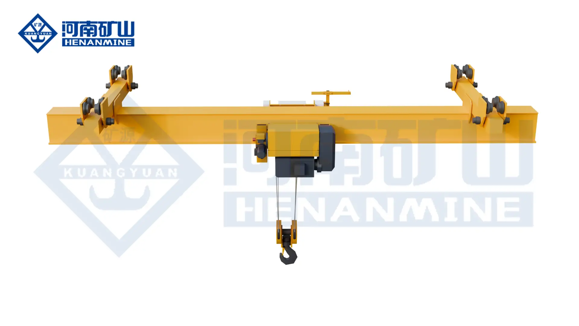
    info@hnksglobal.com
  • Same-Tonnage Crane Prices: Compare Configuration and Supply Boundaries

    Same-Tonnage Crane Prices: Compare Configuration and Supply Boundaries

    Technical guide

    Same-Tonnage Crane Prices: Compare Configuration and Supply Boundaries

    Two cranes with the same nominal capacity can represent different technical and commercial offers. Compare the geometry, duty, lifting mechanism and project responsibilities before treating their prices as directly equivalent.

    Henan Mine CraneTechnical guide · Updated 2026Crane selection, project scope and operating requirements
    crane price factors
    crane price factors
    Project planning notes

    Key points for this crane project.

    1. 8 Key Factors That Make Crane Prices Different
    2. What Is Usually Included in a Crane Quotation?
    3. How to Compare Crane Prices Correctly
    Read the technical guide

    8 Key Factors That Make Crane Prices Different

    The root cause of the price difference between cranes of the same tonnage is the differentiated superposition of multi-dimensional configurations and standards. For customers with commercial research and equipment procurement needs, accurately mastering the eight core price influencing factors is the key to learning how to compare crane quotations, avoiding procurement traps, and achieving cost-effective procurement. The following are the most core pricing factors in the industry, fully covering the core variables of industrial crane prices.

    Crane type and structural design

    The category and structural design of Henan Mine Crane cranes are the basic factors that determine the price of equipment of the same tonnage. The production technology, steel usage, load-bearing design, and manufacturing difficulty of different structural forms vary greatly, which directly determines the core manufacturing cost. It is also the primary core index of crane price factors. First of all, there is a significant price difference between single-beam and double-beam cranes. Under the same tonnage conditions, double-girder cranes adopt a double-girder load-bearing structure. Compared with single-girder equipment, the steel consumption is greatly increased. At the same time, the main girder has stronger bending, torsional and load-bearing stability, and the production welding and assembly processes are more complex.

    Secondly, the structure of bridge cranes and gantry cranes is significantly different. The bridge crane is installed on the steel structure track of the plant, and the structure is relatively streamlined. Gantry cranes require independent gantry support structures, the overall frame volume is larger, the amount of steel is more, and the production and processing standards of outdoor floor-standing designs are higher. The price of gantry cranes of the same tonnage is generally higher than that of bridge cranes. In addition, the top-up and bottom-up operating structures will also affect pricing. The operating mechanism of the top-mounted crane trolley is located above the main girder, with reasonable load-bearing layout, high structural strength, good operating stability, and higher requirements for the main girder technology.

    Span and lifting height

    Crane span and lifting height are the core shape parameters, and they are also price variables that can easily be ignored by purchasing personnel. The core logic is that under the same tonnage parameters, the larger the equipment size, the higher the manufacturing cost, which directly affects the positioning of industrial crane price. The span of the crane directly determines the design standard of the main girder and the amount of consumables. Under the same 20-ton rated load, the design of the main girder with an 18-meter span is completely different from that of the 30-meter span. The longer the span, the greater the bending moment and torque that the main girder needs to withstand.

    The lifting height determines the configuration specifications of the lifting mechanism such as the hoist, wire rope, pulley block, etc. The higher the lifting height, the longer the high-strength wire rope, the larger the rope capacity of the reel, and the more adaptable lifting drive components are required. At the same time, the stability and braking accuracy of the lifting system are higher. In addition, the on-site installation conditions of some factories are limited, and the main girder and support structure of the crane need to be reinforced and customized, or adapted to special track sizes, which will further increase the design and transformation costs.

    Working duty and lifting frequency

    The working level and lifting frequency are the core hidden factors that distinguish the cost performance and adaptability of cranes of the same tonnage, and they are also the core difference between professional procurement and ordinary inquiry. The vast majority of low-cost cranes of the same tonnage are low-profile models in light working conditions and cannot be adapted to high-frequency production scenarios. According to the international standards of FEM, ISO, and CMAA, the industry divides cranes into different working levels, and the core is divided into two types: light working conditions and heavy working conditions. Class A1-A3 cranes in light working conditions are suitable for occasional operations, single-day operations, and low lifting frequency scenarios, such as sporadic loading and unloading in warehouses, intermittent equipment maintenance, durability of accessories, low redundancy design of the whole machine, and low cost.

    What Is Usually Included in a Crane Quotation?

    Many buyers are puzzled that the quotation gap between different manufacturers of the same tonnage crane is very wide. The core reason is not only the difference in configuration, but also the different scope of the quotation. Low-price quotations are often simple equipment quotations, and a large number of supporting projects are missing. Additional installation and construction are required in the later stage, and the final landing cost far exceeds expectations. In order to help buyers accurately check quotations and avoid invisible consumption, the following is a standard crane quotation checklist.

    ItemIncluded?
    Main crane structure✓
    Hoist✓
    Trolley✓
    Electrical system✓
    Control system✓
    Safety devices?
    Power supply system?
    Installation?

    It is clear from the quotation list that the infrastructure and core institutions are standard for all quotations, but most low-cost quotations for safety accessories, power supply systems, installation and commissioning, transportation, spare parts, and quality assurance services are not included. When purchasing and comparing, you can't just look at the unit price of bare metal. You must unify the scope of the quotation. This is the core basis of how to compare crane quotations.

    How to Compare Crane Prices Correctly

    Combining all the above price influencing factors and quotation rules, according to the commercial research and equipment selection needs of purchasing personnel, a set of standardized and landing crane price comparison procurement processes have been compiled to completely solve the misunderstanding of price comparison of equipment of the same tonnage, and accurately screen Henan Mine Crane industrial cranes that are cost-effective and adapted to working conditions.

    Step 1: Confirm the actual lifting requirements

    Get rid of the misunderstanding that only the maximum tonnage is used as the selection standard, and accurately sort out the actual lifting requirements. Clarify the conventional lifting load and maximum limit load of the equipment, and distinguish between daily operating load and sudden heavy load requirements. Count the number of lifting times per day and hour, clarify the lifting frequency, distinguish between intermittent light working conditions and continuous heavy working conditions, and provide a basis for the selection of equipment working level, so as to avoid the problem of waste of high configuration and insufficient low configuration from the root cause.

    Step 2: Confirm key dimensions

    Accurately check the on-site installation size parameters and unify the price comparison standards. Focus on confirming the core dimensions such as the effective span of the crane, the maximum lifting height, the total length of the track operation, and the limit distance of the hook. All inquiry manufacturers must quote based on unified size parameters to avoid price errors caused by the deviation of span and lifting height, and to ensure the fairness and accuracy of price comparison.

    Step 3: Define the working duty

    Clarify the intensity of equipment operation and lock in the work level standards. Count the daily working time of the equipment, the number of working days per month, and the production shift, combined with the lifting frequency, to determine the FEM/ISO work level required by the equipment. Heavy-duty equipment must be selected for multi-shift high-frequency operations, and light-load models can be selected for low-frequency intermittent operations to control costs as needed.

    Step 4: Define the working environment

    Comprehensively sort out the on-site operating environment and confirm whether customized transformation is required. Distinguish between indoor or outdoor operation scenarios, verify the temperature, dust concentration, and humidity of the operating environment, confirm whether there are special working conditions such as corrosion, salt spray, flammable and explosive, and clarify customized requirements such as explosion-proof, anti-corrosion, dust-proof, and weather-resistant in advance, so that manufacturers can issue accurate quotations based on the actual environment to avoid price increases in later retrofits.

    Step 5: Compare complete configurations

    After completing the standardization of all parameters, carry out a full range of configuration price comparison, and refuse a single tonnage price comparison. Don't just compare bare metal quotations for cranes of the same tonnage, but comprehensively compare a full set of configuration and service plans, including all items such as rated tonnage, operating span, lifting height, working level, lifting mechanism, drive control system, safety configuration, installation and commissioning, transportation and quality assurance. Only when the parameters, configuration, services, and qualifications are completely unified can an accurate and effective crane cost comparison be achieved, and truly cost-effective lifting equipment can be selected.

    Henan Mine Crane

    The price of a crane is never determined by a single tonnage. Even if the rated tonnage is exactly the same, the structure, operating span, lifting height, working level, core accessories, control system, and customized requirements for special working conditions will cause significant price differences. If purchasing personnel only compare tonnage quotations, it is easy to ignore hidden costs such as inefficient equipment, frequent failures, and shortened service life. If you want to accurately complete the crane cost comparison, the purchaser must comprehensively check the full set of technical parameters, the adaptability of actual working conditions and supporting services, so as to eliminate the one-sided misunderstanding of the price comparison of a single parameter.

    As a professional industrial crane manufacturer, Henan Mine Crane Factory can provide standardized and customized lifting solutions according to the actual working conditions of customers, covering different working levels, operating spans, and lifting heights. At the same time, it supports explosion-proof, anti-corrosion and other special environmental customization, complete equipment qualifications, stable and reliable performance. If you need accurate crane quotation and professional procurement guidance, you can contact us at any time to obtain a highly adaptable and cost-effective exclusive solution.

    Discuss the crane arrangement for your project.

    Two cranes with the same nominal capacity can represent different technical and commercial offers. Compare the geometry, duty, lifting mechanism and project responsibilities before treating their prices as directly equivalent. Share the load, available drawings, working cycle and site conditions with Henan Mine Crane so the required configuration and supply boundary can be discussed.

    Related crane configurations

    Explore crane product families and technical parameters ↗

    Updated 2026 · Henan Mine Crane

  • Dust-Proof Explosion-Proof Overhead Crane

    Dust-Proof Explosion-Proof Overhead Crane

    Overhead Cranes / Henan Mine Crane

    Dust-Proof Explosion-Proof Overhead Crane

    Configure suspended lifting for a declared combustible-dust environment. Dust classification, surface-temperature limits and enclosure requirements form part of the crane and hoist specification.

    Lifting capacity1t – 10t
    Span7.5m – 28.5m
    Working classA3 – A5
    Technical specifications

    Define the total suspended load, duty and site conditions for your project.

    Technical specifications

    Check the load.
    Plan the configuration.

    Parameters and equipment options are matched to the application and confirmed in the technical proposal.

    Discuss your configuration
    Rated Lifting Capacity1t – 10t
    Basic Span7.5m – 28.5m
    Lifting Height6m – 20m
    Hazardous-area configurationMatched to the declared area classification, material group and temperature requirements
    Hoist TypeSpecial dust explosion-proof electric hoist
    Drive MotorDust explosion-proof type motor
    Working ClassA3 – A5
    Lifting Speed2m/min – 10m/min
    Crane Travel Speed15m/min – 25m/min
    Control ModeDust explosion-proof ground handle / wireless remote
    Power Supply380V/50Hz; 220V-660V/60Hz
    Protection LevelIP65
    Working Temperature-20℃ ~ 45℃
    Structural FeatureLightweight + modular assembly

    Final parameters, dimensions, wheel loads and supply scope follow the approved project specification.

    Application & operation

    Matched to the handling task.

    Dust-producing processes

    Provide lifting coverage around material transfer or process equipment.

    Classified production bays

    Coordinate the hoist, drives and operator controls with the declared dust environment.

    Selection considerations

    Start with your operating conditions.

    01

    Load & lifting arrangement

    Specify load, lifting accessory and dust characteristics. Include lifting-appliance weight and the required lifting positions.

    02

    Site & available space

    Provide suspended runway layout, clearances and cleaning access. Coordinate the installation interfaces with the available site drawings.

    03

    Duty & control sequence

    Define dust area classification, temperature requirements and operating cycle. Identify the required movements and control interfaces in the enquiry.

    Configuration comparison

    Compare related lifting arrangements.

    Crane arrangementHandling configuration
    Dust-Proof Explosion-Proof Overhead CraneConfigure suspended lifting for a declared combustible-dust environment. Dust classification, surface-temperature limits and enclosure requirements form part of the crane and hoist specification.
    Explosion-Proof Suspended Overhead CraneProvide suspended electric-hoist lifting within a declared hazardous area. Review the overhead support, lifting duty and protection of the hoist, travel drives and controls as one system.
    Explosion Proof Electric Hoist Bridge CraneUse an electric-hoist bridge arrangement for a declared hazardous area. The hoist, drives, controls and electrical installation are specified for the area classification and lifting duty.
    Clean Explosion Proof Bridge CraneCombine overhead lifting with the declared cleanliness and hazardous-area requirements. Specify particle-control expectations, process exposure and area classification for the complete lifting system.

    Operating protection & lifecycle support

    Plan beyond the equipment.

    01

    Operating protection

    Confirm overload protection, travel limits, brakes, emergency controls and the required process interlocks for the declared lifting task.

    02

    Installation & commissioning

    Agree runway reactions, structural interfaces, electrical connections, assembly, inspection and commissioning responsibilities before delivery.

    03

    Inspection & spares

    Plan inspection and maintenance of dust-exposed enclosures, sealing components and protected controls. Agree service access, documentation and the required spare-parts scope.

    Questions before the order

    Clarify the details
    that shape the crane.

    What information is needed for a dust-proof explosion-proof overhead crane quotation?+

    Provide load, lifting accessory and dust characteristics; suspended runway layout, clearances and cleaning access; and dust area classification, temperature requirements and operating cycle. Include drawings and the project destination when available.

    Is dust enclosure protection sufficient by itself?+

    Provide the combustible-dust classification and temperature requirements as well as ingress-protection needs. The complete equipment configuration must be reviewed against the declared application.

    What installation and support scope should be agreed?+

    Agree runway reactions, structural interfaces, electrical connections, assembly, inspection and commissioning responsibilities before delivery. Specify the documentation, training and spare-parts support needed for the project.

    Related equipment

    Explore the alternatives.

    Let’s discuss your project

    The right crane starts
    with your lifting task.

    Share load, lifting accessory and dust characteristics, together with your site layout and operating cycle.
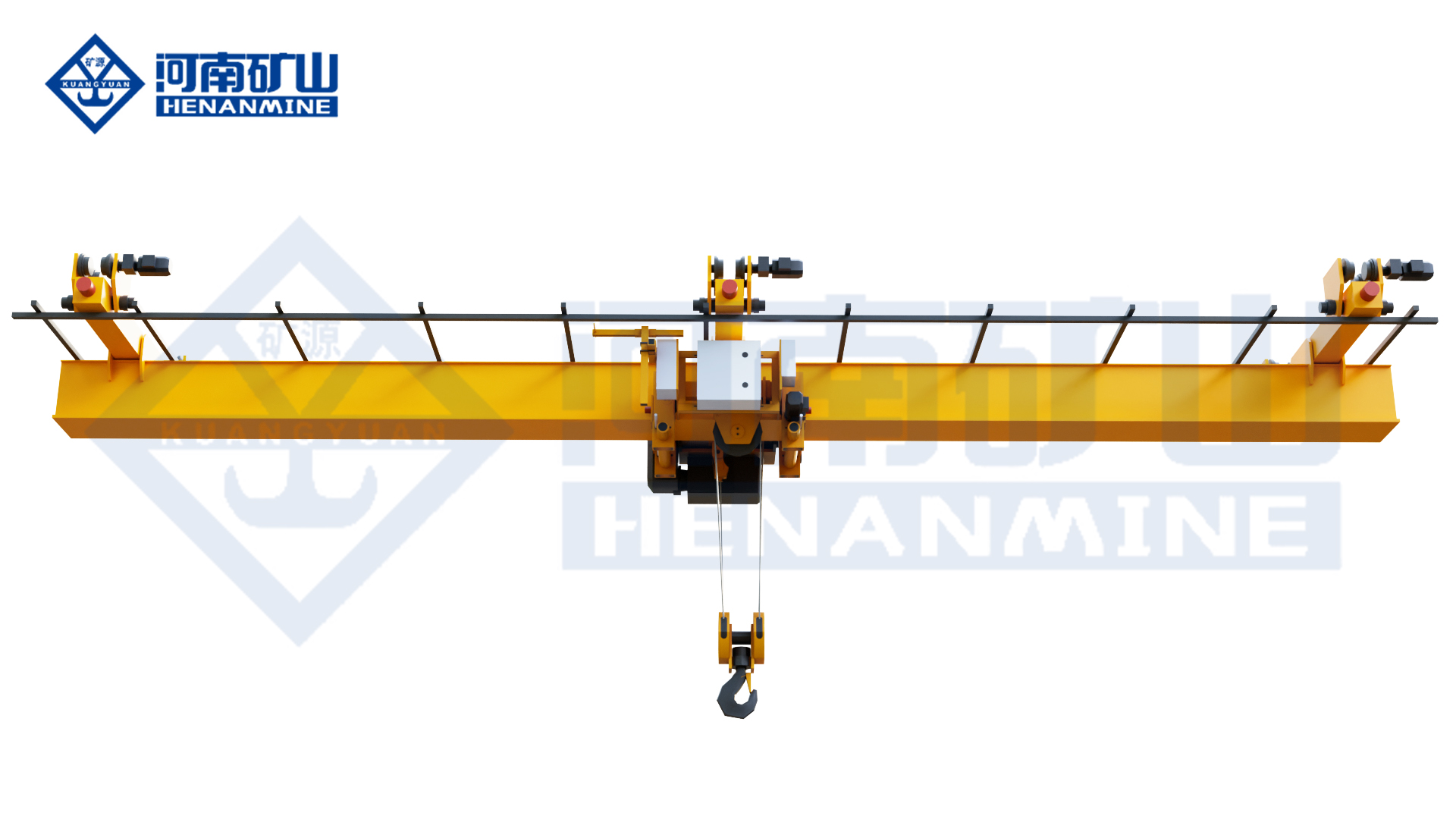
    info@hnksglobal.com
  • Dual Trolley Explosion Proof Bridge Crane

    Dual Trolley Explosion Proof Bridge Crane

    Overhead Cranes / Henan Mine Crane

    Dual Trolley Explosion Proof Bridge Crane

    Combine two-trolley handling with the declared hazardous-area specification. Coordinate hook loads, lifting sequence, electrical protection and operator controls for the complete installation.

    Lifting capacity20+20t
    Span10m – 35m
    Working classA4 – A6
    Technical specifications

    Define the total suspended load, duty and site conditions for your project.

    Technical specifications

    Check the load.
    Plan the configuration.

    Parameters and equipment options are matched to the application and confirmed in the technical proposal.

    Discuss your configuration
    Capacity20+20t
    Span10m – 35m
    Lifting height6m – 30m
    Working classA4 – A6
    Hoisting speed1m/min – 8m/min
    Trolley travel8m/min – 25m/min
    Crane travel10m/min – 30m/min
    Power supply380V/50Hz; 220V-660V/60Hz
    ControlsCabin/ground handle/wireless remote/PLC linkage

    Final parameters, dimensions, wheel loads and supply scope follow the approved project specification.

    Application & operation

    Matched to the handling task.

    Long hazardous-area loads

    Coordinate two lifting points within a classified production bay.

    Process equipment handling

    Match the lifting arrangement to the equipment and surrounding hazardous conditions.

    Selection considerations

    Start with your operating conditions.

    01

    Load & lifting arrangement

    Specify load at each hook and the intended combined lifting sequence. Include lifting-appliance weight and the required lifting positions.

    02

    Site & available space

    Provide trolley spacing, runway positions and maintenance access. Coordinate the installation interfaces with the available site drawings.

    03

    Duty & control sequence

    Define hazardous-area classification, temperature and control requirements. Identify the required movements and control interfaces in the enquiry.

    Configuration comparison

    Compare related lifting arrangements.

    Crane arrangementHandling configuration
    Dual Trolley Explosion Proof Bridge CraneCombine two-trolley handling with the declared hazardous-area specification. Coordinate hook loads, lifting sequence, electrical protection and operator controls for the complete installation.
    Explosion-Proof Bridge CraneUse a QB bridge crane for lifting in a declared explosive-gas environment. Select the load rating, main and auxiliary arrangement, electrical protection and control mode for the project.
    Explosion Proof Electric Hoist Bridge CraneUse an electric-hoist bridge arrangement for a declared hazardous area. The hoist, drives, controls and electrical installation are specified for the area classification and lifting duty.
    Double Trolley Electric Hoist CraneLift long components or serve separate working positions with two electric-hoist trolleys on one bridge. Trolley spacing, load sharing and independent or coordinated operation are specified for the task.

    Operating protection & lifecycle support

    Plan beyond the equipment.

    01

    Operating protection

    Confirm overload protection, travel limits, brakes, emergency controls and the required process interlocks for the declared lifting task.

    02

    Installation & commissioning

    Agree runway reactions, structural interfaces, electrical connections, assembly, inspection and commissioning responsibilities before delivery.

    03

    Inspection & spares

    Plan inspection and maintenance of trolley interlocks, lifting mechanisms and protected electrical enclosures. Agree service access, documentation and the required spare-parts scope.

    Questions before the order

    Clarify the details
    that shape the crane.

    What information is needed for a dual trolley explosion proof bridge crane quotation?+

    Provide load at each hook and the intended combined lifting sequence; trolley spacing, runway positions and maintenance access; and hazardous-area classification, temperature and control requirements. Include drawings and the project destination when available.

    What must be reviewed for coordinated two-trolley operation?+

    Provide hook loads, lifting-point spacing, the load centre of gravity and the hazardous-area classification. The proposal defines permitted operating combinations and the protection of each relevant component.

    What installation and support scope should be agreed?+

    Agree runway reactions, structural interfaces, electrical connections, assembly, inspection and commissioning responsibilities before delivery. Specify the documentation, training and spare-parts support needed for the project.

    Related equipment

    Explore the alternatives.

    Let’s discuss your project

    The right crane starts
    with your lifting task.

    Share load at each hook and the intended combined lifting sequence, together with your site layout and operating cycle.
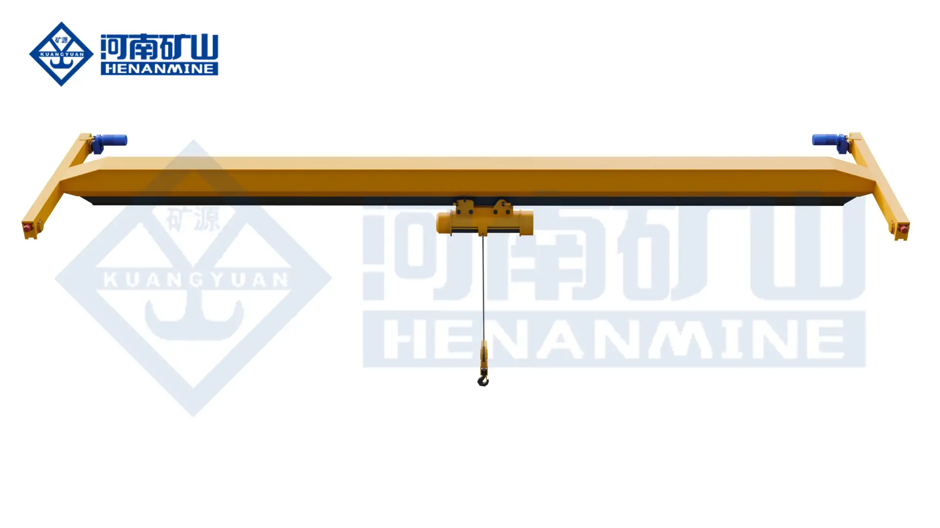
    info@hnksglobal.com
  • Lifting Hook Selection: Load Connection and Component Documentation

    Lifting Hook Selection: Load Connection and Component Documentation

    Technical guide

    Lifting Hook Selection: Load Connection and Component Documentation

    Hook selection needs to follow the approved lifting arrangement and intended service. Identify the load connection, appliance and operating conditions, then request the documentation and inspection information relevant to the selected component.

    Henan Mine CraneTechnical guide · Updated 2026Crane selection, project scope and operating requirements
    Henan Mine Crane Electromagnetic Hook Double Gantry Crane
    Henan Mine Crane Electromagnetic Hook Double Gantry Crane
    Project planning notes

    Key points for this crane project.

    1. What Is a Crane Hook?
    2. Common Crane Hook Types
    3. Crane Hook Materials and Manufacturing
    Read the technical guide

    What Is a Crane Hook?

    Crane hooks are special lifting and hoisting accessories. As the core load-bearing interface between cranes, winches and hoisting loads, they are mainly used to connect hook pulley blocks, winches and slings, shackles, chains, hoisting beams and other rigging accessories to achieve smooth lifting, shifting and dropping of heavy objects.

    Unlike ordinary hardware hooks, crane hooks are industrial-grade load-bearing components. They are manufactured by professional engineering design and rigorous technology. They can withstand high-strength tensile, impact, bending and cyclic fatigue loads. They are the core safety components of lifting operations.

    Common Crane Hook Types

    Crane hooks can be classified in four dimensions according to structure, manufacturing process, connection method and functional characteristics. They mainly include single and double hooks, forged/laminated, various connections and safety self-locking styles. They are widely adapted to various types of lifting equipment and are used in heavy lifting operations in construction, manufacturing, ports, metallurgy and other industries.

    Single hook

    The most popular basic hook style on the market has only one load-bearing hook. The overall structure is simple, the weight is light, and the production and daily flaw detection and inspection are very convenient. It is mostly used for general industrial cranes, which are suitable for scenarios where the lifting space is limited and the lifting process is simple. When lifting large-weight objects, load eccentricity is prone to occur.

    Double hook

    It has two symmetrical hook bodies, sharing a hook handle, and its shape resembles a sheep's horn.

    It is mostly used in metallurgy, ship construction, steel structure processing, and port industries, and is suitable for hoisting long heavy objects such as steel beams and pipes. Some industry standards refer to it as DIN 15402 hook.

    Forged hooks and laminated hooks

    1. Forged hooks: formed from alloy steel by high-pressure forging process, the overall strength is high, the toughness is good, and the durability is durable. It is the mainstream manufacturing process of conventional single hooks and double hooks.
    2. Laminated hook: It is made of multi-layer steel plates stacked and bolted and assembled. It is mostly used for customized lifting scenarios with high-capacity. The advantage is that the bearing capacity is extremely strong, and the steel plate can be replaced separately after damage, which is convenient for maintenance.

    Different connection structure and function hooks

    • Ring eye hook: The top adopts a closed ring structure, which can be easily matched with various hoisting accessories such as slings and shackles, which are suitable for general light-load hoisting conditions, and are mostly used for normal hoisting operations at fixed points.
    • Clamp hook: The lifting accessories are fixed by the pin shaft locking structure, which is stable in connection and easy to disassemble and assemble. It is a common mainstream style for binding and hoisting on the construction site.
    • Straight shank hook: It is a standard supporting accessory for cranes, divided into two types: smooth straight shank and threaded straight shank.
    • Rotating hook: Built-in precision bearing rotating mechanism, which can achieve 360° unhindered rotation, effectively avoiding load torsion and rope winding problems during lifting, and greatly improving the flexibility and adaptability of lifting operations.
    • Self-locking safety hook: Equipped with mature self-locking buckle structures such as Shur-Loc, Latchlok, and Bullard, it has a protective function to prevent accidental decoupling, which can effectively avoid the risk of falling off the spreader during hoisting operations, and significantly improve the safety and stability of heavy-duty hoisting.

    Other special special hooks

    • Sorting hook: The hook type is slender and sharp, which is tailored to the sorting and hoisting operations of logs, pipes, and various types of bundled materials, with accurate grasping and strong practicality.
    • C-shaped hook: It adopts an exclusive C-shaped structure design, which is specially designed for hoisting various types of rolled materials such as steel coils and paper rolls. It fits the shape of the material, and the hoisting is stable and not easy to slip off.
    • Special working condition hooks: including casting hooks, J-shaped hooks, grappling hooks, barrel hooks and other categories, they are all customized for subdivided working conditions and are suitable for special scenarios such as casting operations, pipe hoisting, and barreled material handling, with strong adaptability.
    • Electric rotary hook: integrated motor drive structure, which can realize automatic electric rotation without manual auxiliary torsion, effectively improving the operating efficiency and control flexibility of heavy-duty hoisting.

    Crane Hook Materials and Manufacturing

    Classification of materials and applicable scenarios

    • Alloy steel: The mainstream materials are nickel-chromium-molybdenum alloy steels such as 34CrNiMo6, 30CrNiMo8, and 34CrMo4. It has high strength, high toughness, and low temperature impact resistance. It is suitable for heavy-duty and high-frequency hoisting scenarios such as ports, metallurgy, wind power, and heavy industries. It is the preferred material for industrial hooks.
    • Carbon steel steel: represented by 20# steel and A36 steel, it has lower cost, excellent ductility and forging properties, and moderate overall strength. It is only suitable for light and medium-sized conventional hoisting operations, and is not suitable for heavy loads, impact loads, and high-frequency working conditions.
    • Low-alloy high-strength steel : mainly DG20Mn and A572 Grade 50, with a balanced strength-to-weight ratio and high cost performance, it is widely used in medium-load hoisting scenarios of ordinary factories and small and medium-sized lifting equipment.
    • Stainless steel steel: 316/316L austenitic stainless steel, 410 martensitic stainless steel, with strong corrosion resistance and rust resistance, suitable for marine, chemical, food and medicine and other humid and corrosive environments. The disadvantage is that the strength and fatigue resistance are lower than that of alloy steel, and the procurement cost is higher.

    Standardized manufacturing process

    1. Simulation design optimization: Through CAD modeling + finite element stress analysis (FEA), the curvature, shank diameter, and opening size of the hook are optimized to evenly disperse the load-bearing stress, and the design safety factor can reach 4:1 or more than 5:1.
    2. Raw material selection and testing: select high-quality steel billets, detect chemical composition, mechanical properties, and internal defects, and cut standard-size raw materials to eliminate unqualified substrates.
    3. Core forging processing: free forging and die forging processes are used, and thousands of tons of pressure are formed to make the metal streamline fit the contour of the hook, greatly improving the structural density, impact resistance and fatigue resistance. Large-scale customized hooks adopt composite forging technology to ensure overall stability.
    4. Quenching and tempering heat treatment: Through the integrated treatment of normalizing, quenching and tempering, the steel grains are refined and the internal stress of forging is eliminated, so that the hook can take into account the high strength and high toughness, and prevent the deformation and fracture failure of the hoisting from the root cause.
    5. Precision machining: remove excess flying edges from forging, adopt CNC precision machining of key structures such as threads, buckle holes, and load-bearing arcs, and match shot blasting and painting processes to achieve anti-corrosion and anti-rust, while improving the accuracy of components and the overall appearance quality.
    6. Identification and packaging: Key parameters such as rated load, manufacturer information, and traceability number are permanently engraved on the hook body, and an EN 3.1 material testing certificate is issued. After professional protective packaging, the product is shipped out of the factory to ensure that the product is traceable and transported without damage.

    Understanding Crane Hook Load Capacity

    The load capacity is the most core parameter of the hook, which refers to the maximum weight that the hook can safely carry under standard working conditions. It is jointly defined by design, material, technology, and industry standards, and is the core basis for selection and operation.

    Core load jargon

    • Rated working load (SWL/WLL): The maximum weight allowed to be carried by the hook in daily operations, which is permanently engraved on the surface of the hook body, which is the only reference standard for on-site hoisting operations.
    • Test load (verification load): The pressure test load that is shipped from the factory and regularly tested is usually 1.25-2 times the rated load. The hook is qualified if there is no permanent deformation and no cracks under this load.
    • Ultimate destructive load: The critical load for the hook to break or fail. Industry standards require that the ultimate load be 4-5 times the rated load, and sufficient safety margin is reserved.
    • Safety factor: The ratio of rated load to ultimate load, the standard safety factor of industrial hooks is 4:1-5:1, which can offset the safety risks caused by dynamic impact, wear, and fluctuations in working conditions.

    Basis for determining load capacity

    1. Material properties: The tensile strength, yield strength, and fatigue resistance of steel are the basis of load, and high-strength alloy steel can achieve greater load-bearing in a smaller volume.
    2. Structural geometry and stress design: dimensional parameters such as hook opening, hook shank diameter, and load-bearing arc surface, combined with finite element stress optimization, determine the uniformity of load distribution and avoid local stress concentration failure.
    3. Factory pressure test verification: Each hook has passed the pressure test test of the rated multiple load to ensure that the design matches the actual load-bearing capacity.
    4. Industry standard constraints: follow ASME B30.10, DIN 15401/15402, ISO 12209, GB/T 10051 and other standards, and unify load classification, testing, and marking specifications.

    Load identification specification

    Hooks with vague and missing logos are strictly prohibited from being put into use, and there are major safety risks if the load capacity cannot be confirmed.

    Factors That Affect Crane Hook Load Capacity

    The rated load of the hook is the standard static working condition parameter. In actual operation, a variety of working conditions, environment, and equipment problems will greatly reduce the effective load-bearing capacity, which can easily cause overload accidents and need to be avoided.:

    Design and manufacturing factors

    Problems such as insufficient design safety factor, substandard raw material materials, substandard heat treatment technology, forging defects, and poor dimensional tolerances will all weaken the actual carrying performance of the hook, making it lower than the rated standard, and laying hidden dangers of fracture and failure.

    Work force factor

    • Lateral force/cable-stayed force: The hook is only adapted to vertical linear force.
    • Dynamic impact load: The impact force generated by the rapid lifting of heavy objects, sudden start and stop, and the shaking of the load will instantly amplify the actual load-bearing and exceed the static rated load bearing range.
    • Offset of the force position: The load is hung on the tip of the hook instead of the central load-bearing arc, which will cause local stress concentration and greatly reduce the load-bearing stability.

    Ambient temperature factor

    At extreme temperatures, the hook load needs to be derated to avoid brittleness and deformation failure. The corrosive environment will cause pitting and stress corrosion cracks in steel, and continue to lose load-bearing capacity.

    Equipment wear

    Long-term high-frequency hoisting will produce cyclic fatigue loads and breed microcracks; wear and reaming of the hook mouth, bending and deformation of the hook body, surface scratches, damage to the buckle, and lack of marking wear will directly lead to load degradation, and it must be discontinued in time for maintenance.

    How to Choose the Right Crane Hook

    Suitable hooks are the basis for hoisting safety. The selection needs to combine the four dimensions of load, working conditions, environment, and standards, and follow the following standardized steps:

    Calculate the required rated load

    At the same time, check the hook safety factor (above 4:1) and the test load parameters.

    Matching hook type and structure

    • Single hook: The most versatile, suitable for most conventional light, medium and heavy-duty hoisting scenarios, divided into eye-type, shank-type, and shackle-type structures.
    • Rotating hook: it comes with a rotating bearing, which can avoid torsion and entanglement of rigging, and is suitable for special-shaped and rotatable load hoisting.
    • Special hooks: insulated hooks, high temperature resistant hooks (for metallurgical high temperature scenarios), weighing hooks, suitable for special working conditions.

    Adapt to operating conditions and environment

    Match the size of the hook according to the load shape, center of gravity position, hoisting frequency, and rigging type; stainless steel hooks are selected for corrosion/marine environments, heat-resistant alloy steel hooks are selected for high-temperature working conditions, high-toughness alloy steel hooks are selected for low-temperature impact working conditions, and explosion-proof and anti-magnetic special hooks are selected for high-risk scenarios.

    Screening regular manufacturers and after-sales service

    When selecting models, priority should be given to screening regular manufacturers with perfect quality control system and professional non-destructive testing qualifications, and priority should be given to high-quality brands that support non-standard customization and provide a full set of after-sales maintenance and quality assurance, so as to eliminate non-standard inferior hooks from the source and ensure the safety of equipment operation.

    Crane Hook Inspection and Maintenance

    Detection type and frequency

    • Daily visual inspection before shift: The operator checks before each shift to check whether the hook has cracks, deformation, buckle damage, missing identification, and serious wear and tear, and to investigate the hidden dangers of the hook. There is no need to force written records. It is recommended that the company keep the ledger.
    • Regular professional testing: carried out by licensed professionals, regular working conditions are at least once a year, and the testing cycle needs to be shortened for high-frequency, heavy-duty, and harsh environments; it can be used with magnetic powder and ultrasonic nondestructive testing to investigate hidden internal cracks. The OSHA specification requires bridge crane hooks to carry out monthly written record inspections.

    Hook mandatory deactivation standard

    If the hook has any of the following faults or defects, it must be immediately stopped from use and removed from the shelf for isolation. After being tested and evaluated by professionals or replaced with brand new accessories, it can be put back into operation.:

    • The original factory logo such as the rated load of the hook body, the manufacturer's number, etc. is blurred, faded or completely off, and the equipment parameters and traceability information cannot be verified.;
    • Structural damage such as cracks, deep scratches, pits, corrosion and pitting on the surface of the hook body, and the depth of the defect reaches the standard for determining whether the nail can be stuck.;
    • The hook body produces visual bending and torsional deformation, and the overall distortion angle exceeds 10°, which exceeds the standard allowable deviation range.;
    • Safety and anti-release buckle is damaged, missing, stuck or action fails, and cannot reliably lock and prevent the sling member from falling off.;
    • The hook has traces of illegal maintenance such as welding, polishing, and restructuring without authorization, resulting in damage to the structural integrity and mechanical properties of the body.

    Daily maintenance best practices

    Standardized daily maintenance can effectively extend the service life of the hook and avoid hidden dangers of equipment. The industry's general standardized maintenance specifications are as follows:

    • Clean and rust-proof: Regularly clean up oil, dust and debris on the surface of the hook body, keep the components clean, facilitate daily investigation of hidden dangers, and prevent corrosion and pitting caused by long-term attachment of corrosive media.
    • Regular lubrication: For movable structures such as buckle shafts and rotating hook bearings, special lubricating greases are regularly filled to ensure flexible operation of components and reduce friction loss and the probability of stuck failure.
    • Standardized storage: Idle hooks should be stored in a dry, clean and ventilated indoor environment, with anti-collision, anti-rust, and sun protection to avoid damage to components caused by external force bumps and environmental corrosion.
    • Illegal maintenance is prohibited: It is strictly prohibited to carry out transformation operations such as welding, polishing, and welding of hooks without authorization. Damaged parts must be replaced with original supporting authentic products to eliminate safety risks caused by non-standard maintenance.
    • Post-failure re-inspection: After the hook undergoes abnormal working conditions such as overload, impact, and fall, load pressure testing and non-destructive testing must be carried out to verify the structural strength and integrity, and it can be put into use again after passing the test.

    Discuss the crane arrangement for your project.

    Hook selection needs to follow the approved lifting arrangement and intended service. Identify the load connection, appliance and operating conditions, then request the documentation and inspection information relevant to the selected component. Share the load, available drawings, working cycle and site conditions with Henan Mine Crane so the required configuration and supply boundary can be discussed.

    Related crane configurations

    Electromagnetic Hook Double Gantry Crane

    View product parameters
    Lifting capacity: 10-50 tSpan: 18-35 mLifting height: 8 – 24 m

    Handle steel products with a gantry arrangement combining hook and electromagnetic lifting functions. Define the trolley arrangement, load cases and changeover sequence for the yard.

    Grab And Hook Dual Purpose Crane

    View product parameters
    Lifting capacity: 5 – 16 tSpan: 10.5 – 31.5 mLifting height: 6 – 20 m

    Switch between bulk-material pickup and hook lifting with a grab-and-hook overhead arrangement. Define each load case, the grab type and the changeover procedure for the working area.

    Updated 2026 · Henan Mine Crane