Engineering · Manufacturing · Project support
info@hnksglobal.comWhatsApp +86 18836207779 ↗

Blog

  • Henan Mine Crane Presents Lifting Equipment at the 2024 Supply Chain Expo

    Henan Mine Crane Presents Lifting Equipment at the 2024 Supply Chain Expo

    Industry & Partnerships

    Henan Mine Crane Presents Lifting Equipment at the 2024 Supply Chain Expo

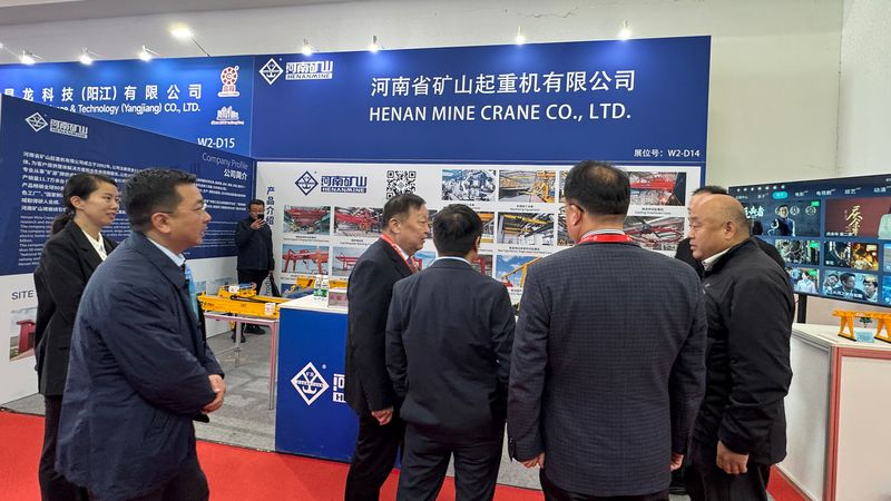
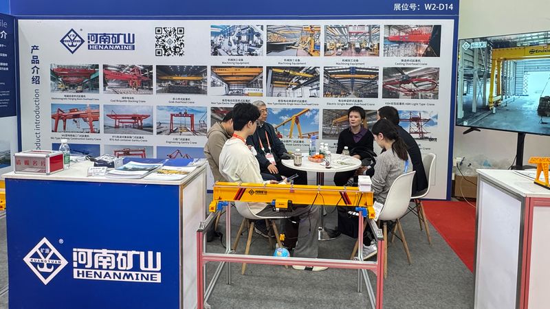
    Henan Mine Crane exhibited at the second China International Supply Chain Expo in Beijing in November 2024.

    Visitors discussing crane applications at the Henan Mine Crane exhibition stand
    Visitors discussing crane applications at the Henan Mine Crane exhibition stand.

    Equipment and supply-chain discussions

    Visitors reviewed the company’s crane manufacturing displays and discussed potential cooperation at the stand. The report documents participation and conversations; it does not establish an equipment specification, certification or purchase order.

    What to request after an exhibition meeting

    A procurement team can move from an initial discussion to a project RFQ by sharing the load and handling path, site dimensions, duty, power supply and delivery destination. Ask for a configuration drawing, component schedule, inspection plan and clearly defined supply boundary.

    Explore Henan Mine Crane

    Share your crane application and project requirements with the engineering team for a specific proposal.

  • Slab Handling Cranes: Stock Arrangement and Transfer Requirements

    Slab Handling Cranes: Stock Arrangement and Transfer Requirements

    Selection guide

    Slab Handling Cranes: Stock Arrangement and Transfer Requirements

    Slab handling depends on product dimensions, lifting tools and the storage or process route. Describe the material condition and transfer sequence so the complete crane and attachment arrangement can be developed for the task.

    Henan Mine CraneSelection guide · Updated 2026Crane selection, project scope and operating requirements
    Slab Handling Crane for Steel Mill Storage and Transfer
    Slab Handling Crane for Steel Mill Storage and Transfer
    Project planning notes

    Key points for this crane project.

    1. What Is a Slab Handling Crane?
    2. Slab Handling Crane Configurations
    3. Compare Slab Lifting and Motion Configurations
    Read the technical guide

    What Is a Slab Handling Crane?

    A slab handling crane is a purpose-engineered metallurgical overhead crane that moves semi-finished steel slabs between production and storage stages. Typical duties include receiving slabs from a continuous caster, clearing a cooling bed, transferring material to inspection or scarfing stations, organizing stockyard stacks, feeding a reheating furnace and loading railcars, trucks or internal transfer equipment.

    The equipment differs from a general hook crane because the slab itself defines the lifting system. Length, width, thickness, surface temperature, camber, scale condition, stack spacing and permitted contact zones determine whether a mechanical clamp, electromagnetic beam, hook beam or another approved attachment can establish secure load control. High cycle frequency and precise placement may also require synchronized lifting, anti-sway, low-speed positioning, coordinate control and production-system communication.

    Rated capacity cannot be selected from slab net weight alone. The engineering basis must identify whether the contractual capacity represents slab payload or gross suspended load. A complete gross-load calculation includes the maximum slab or slab group, clamp or magnet beam, rotating structure, hook blocks, equalizing equipment and every component suspended below the trolley. Dynamic factors and the governing design basis are then applied.

    Henan Mine Crane configures YB slab cranes for hot and ambient handling. Final project drawings define attachment geometry, control logic, safety functions and inspection requirements.

    Slab Handling Crane Configurations

    01 · Mechanical Slab Clamp Crane

    Side-gripping mechanical or powered tongs engage approved slab faces. The arrangement avoids dependence on magnetic holding power and suits defined thickness and width ranges. Jaw geometry, closing force, locking status, surface scale and anti-release protection require project approval.

    02 · Electromagnetic Slab Crane

    A suspended magnet beam lifts magnetically responsive slabs without side access. Fast pickup and release support high-throughput yards, but magnetic duty, slab temperature, air gaps, power continuity, residual magnetism and emergency retention strategy govern suitability.

    03 · Fixed-Orientation Transfer Crane

    A non-slewing lifting system transfers slabs along a consistent storage or production axis. Reduced rotating mass and simpler control can support dependable repetitive handling when pickup and placement orientations remain aligned.

    04 · Rotating Slab Handling Crane

    A slewing trolley or rotating beam changes slab orientation between process bays, stacks, inspection lines and dispatch lanes. Rotation envelope, cable management, load inertia, collision zones and positioning accuracy form part of the crane design.

    05 · Automated Slab Warehouse Crane

    PLC control, encoders, ranging devices, anti-sway, stack coordinates and plant communication support unmanned or supervised automatic cycles. Manual recovery, safe-zone logic, inventory reconciliation and degraded-mode operation remain essential.

    06 · Synchronized Dual-Lift System

    Load sharing, hoist synchronization, skew monitoring, rope reeving and independent protective functions limit twist and unequal loading.

    Compare Slab Lifting and Motion Configurations

    ConfigurationLoad InterfacePrincipal AdvantageEngineering Constraint
    Mechanical slab clampSide faces or defined gripping zonesNo magnetic holding dependency; positive mechanical interfaceRequires approved thickness, width, edge condition and jaw access; contact marks may require review
    Electromagnetic beamUpper slab surface through magnetic attractionFast pickup; no side access; adaptable magnet groupingFerromagnetic material only; air gap, temperature, scale, power loss and residual magnetism affect performance
    Hook or lifting beamEngineered lifting points, chains or approved riggingFlexible for unusual pieces and maintenance loadsSlower cycle; manual rigging exposure; lifting points and sling angles require control
    Non-slewing trolleyClamp, magnet or beam kept on fixed axisSimpler operating path and lower rotating complexityCannot correct orientation without another handling stage
    Slewing trolley or beamAttachment rotates around a controlled vertical axisPlaces slabs across different bay and stack orientationsHigher dead load, headroom demand, inertia and collision-control complexity
    Automatic coordinate handlingAttachment combined with sensors and stored positionsRepeatable stacking, traceable moves and reduced cycle variationRequires reliable slab identity, clear zones, recovery logic and maintained calibration

    Attachment selection rule: slab temperature, magnetic properties, dimensional range, surface condition, stack access and failure consequence must be established before crane capacity, trolley layout and control functions are frozen.

    Slab Handling Applications Across the Steel Process

    Process AreaMaterial ConditionPrimary Handling DemandConfiguration Direction
    Continuous-casting dischargeNewly cast hot slabs leaving the caster or transfer tableHigh radiant heat, production continuity and controlled pickupHeat-shielded clamp crane with precise low-speed approach
    Cooling bed and slab yardHot slabs during staged cooling and buffer storageChanging temperature, stack sequence and large coverage areaClamp or approved magnetic system with coordinated yard travel
    Inspection and conditioningSlabs routed to grinding, scarfing, marking or flaw detectionAccurate presentation and possible orientation changeRotating clamp, magnet beam or engineered lifting beam
    Finished-slab warehouseAmbient slabs stored by grade, heat, order or destinationInventory accuracy, dense stacking and repetitive cyclesAutomated or semi-automated crane with coordinate control
    Reheating-furnace feedSelected slabs transferred from storage to rolling preparationProduction sequencing and furnace charging interfaceHigh-duty crane with controlled placement and plant interlocks
    Rail, truck or internal dispatchSlabs loaded to transport equipment or transfer carsVehicle position variation and personnel separationClamp, magnet or lifting beam with zone monitoring

    A hot-slab transfer crane may prioritize thermal protection, heavy duty and availability; an ambient warehouse crane may prioritize inventory control, positioning and dense storage. Materially different process conditions can require separate operating modes or separate cranes.

    Slab Handling Crane Technical Selection Framework

    The following range reflects the published Henan Mine Crane YB product envelope and a practical quotation framework. It is not a universal rating for every slab, building or destination. Final values appear on the approved project data sheet and general arrangement.

    Selection ItemProject Data RequiredProcurement Control
    Rated lifting capacityMaximum slab mass, number of slabs, attachment mass and contractual capacity definitionConfirm net payload versus gross suspended load before mechanism sizing
    SpanRunway rail-center distance, working coverage, end approaches and building reactionsBuilding clear width is not substituted for crane span
    Lifting heightLowest pickup, highest stack, attachment depth, rail elevation and service clearanceAvailable hook or clamp elevation is checked on a vertical section
    Slab geometryMinimum and maximum length, width, thickness, camber, edge profile and weight distributionEvery attachment operating envelope is approved in writing
    Temperature exposureSlab surface temperature, ambient air, radiant exposure, distance, dwell time and heat cyclesTemperature terms are separated; a slab rating is not treated as ambient-air temperature
    Duty classificationLifts per hour, load spectrum, shifts, annual hours, travel distance and service-life targetCapacity and fatigue duty are evaluated independently
    Motion performanceCycle target, safe high-speed route, low-speed placement, rotation and positioning toleranceSpeed follows process flow, load stability and stopping distance
    Control and powerPlant power, communication protocol, operating station, backup mode and cybersecurity boundaryI/O, interlocks, data ownership and recovery sequence are documented

    Safety and Control Architecture for Slab Handling

    The safety concept covers secure pickup, hoisting, travel, rotation, placement and release under the governing design basis and plant risk assessment.

    Clamp Status and Release Interlocks

    Open, closed and locked states are monitored where applicable. Hoisting permission, load presence and release conditions are interlocked so that a clamp cannot be opened during an unsafe suspended state.

    Magnet Power-Loss Strategy

    Magnetic systems require a documented response to supply interruption. Battery or alternate power, holding-time monitoring, alarms, controlled lowering and restricted personnel zones are selected from the load risk.

    Hoist and Load Protection

    Overload limitation, dual-point synchronization, upper and lower limits, brake monitoring, rope guidance and low-speed positioning protect the lifting path and prevent unequal loading.

    Anti-Sway and Position Control

    Mechanical reeving, VFD motion profiles, encoder feedback and optional electronic anti-sway reduce pendulation. Position tolerance is specified at the attachment and verified through commissioning.

    Travel, Rotation and Collision Zones

    End limits, buffers, anti-collision, slewing limits, clearance monitoring and protected storage coordinates prevent contact with structures, equipment, adjacent cranes and slab stacks.

    High-Temperature Protection

    Heat shields, protected electrical cabinets, temperature-rated cables, appropriate lubrication and component placement reduce radiant exposure. Inspection intervals reflect scale, heat and thermal cycling.

    Automated-Mode Safeguards

    Access control, zone scanning, permissive logic, fault diagnosis, safe stop, controlled restart and manual recovery govern unmanned or supervised cycles.

    Operator and Maintenance Safety

    High-visibility cabin design, cameras, warning devices, isolation points, platforms, access routes and component-removal space support controlled operation and maintainability.

    Crane Structure, Headroom and Operating Logic

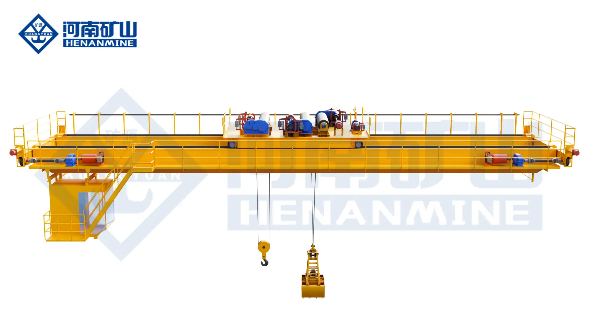
    Heavy slab service commonly uses a top-running double-girder bridge with an engineered winch trolley. The arrangement provides structural stiffness, mechanism access and space for synchronized hoists, a rotating platform or a suspended clamp beam. Long slabs may require two lifting points so that load sharing and slab deflection remain controlled throughout acceleration, travel and placement.

    Headroom is governed by more than hook height. Rail elevation, bridge depth, trolley structure, rope geometry, clamp opening height, slab thickness, required clearance above stacks and maintenance-removal paths must be shown on one dimensioned vertical section. A rotating attachment also requires a verified plan-view envelope at every operating elevation.

    An automatic cycle normally includes destination validation, approach at controlled speed, attachment alignment, secure pickup confirmation, vertical clearance, bridge and trolley travel, optional rotation, stack-position verification, controlled lowering and release confirmation. Fault recovery must define retained load condition, safe manual access and the route back to a known coordinate.

    Stack height, cooling separation, grade segregation, retrieval sequence and buffer locations determine travel distance and cycle time. Motion values should follow the process model rather than maximum speed alone.

    Project Case: 50+50 t Slab Clamping Crane

    The project applies an electrically adjustable slab clamp with positioning control to high-capacity steel-mill material handling.

    Digital speed control and a guiding arrangement support stable heavy-load motion and accurate placement. PLC control, weighing, fault alarms and operating-data functions provide a foundation for monitored production and later automation integration.

    The case demonstrates that dual-point load control, clamp adjustment, thermal protection, positioning, monitoring and maintenance access must operate as one system. Temperature and performance values remain project-specific.

    Engineering, Manufacturing and Quality Documentation

    A slab handling crane should be released through an agreed document and inspection plan. Records connect the approved load case and control philosophy to the fabricated structure, assembled mechanisms and commissioned attachment.

    Approved Design Package

    General arrangement, wheel loads, attachment drawing, lifting-point geometry, mechanism data, electrical demand and control narrative.

    Structural Quality

    Material identification, approved welding procedures, welder qualification, dimensional checks and specified non-destructive examination.

    Mechanism Verification

    Hoist synchronization, brakes, drums, ropes, wheels, reducers, lubrication, rotation drives and maintenance-access checks.

    Attachment Inspection

    Clamp opening range, jaw contact, pins, locks, sensors, magnet circuits, beam geometry and safe-release interlocks.

    Functional Testing

    Motion tests, limits, alarms, overload functions, position feedback, automated sequences and contracted witness points.

    Final Handover

    Final drawings, manuals, configured parameters, inspection records, spare-parts schedule and commissioning documentation.

    Installation, Commissioning and Lifecycle Planning

    Site and Runway Verification

    Confirm rail centers, elevation, alignment, supporting structure, maximum wheel loads, horizontal forces, conductor location, erection access and available assembly space before shipment.

    Shipping and Erection Plan

    Define transport divisions, lifting points, temporary supports, girder assembly, trolley placement, attachment installation, high-temperature protection and site responsibility matrix.

    Cold Commissioning

    Verify travel alignment, brakes, limits, encoders, clamp or magnet functions, rotation, alarms, interlocks, communication and manual recovery without a process load.

    Load and Process Acceptance

    Conduct contracted static, dynamic and functional tests, then validate pickup, transfer, positioning and release using approved trial slabs and controlled operating zones.

    Attachment Maintenance

    Inspect clamp jaws, pins, bushes, locks, guides and sensors; check magnet insulation, cables, power backup and beam condition. Wear limits and replacement criteria belong in the manual.

    Thermal and Electrical Inspection

    Monitor heat shields, cable protection, cabinet cooling, seals, lubrication condition, brakes, ropes and temperature-affected components at intervals derived from actual exposure.

    Automation Support

    Maintain coordinate calibration, sensor health, network interfaces, backups, fault logs and recovery procedures. Software changes require controlled authorization and documented validation.

    Critical Spare Parts

    Plan brakes, encoders, sensors, contactors, VFD-related components, limits, seals, clamp wear parts, cable assemblies and selected magnet-power components around production consequence.

    Slab Handling Crane Price and Project Cost

    Custom slab cranes require project quotation because capacity, attachment, temperature, duty and automation change the system materially. General bridge-crane figures provide only a lower-level market benchmark; they do not represent a fixed Henan Mine Crane slab-crane price.

    Budget LevelIndicative Market PositionTypical ScopeMain Cost Drivers
    Manual slab clamp process craneProject quotationDouble-girder crane, open-winch trolley, engineered clamp and metallurgical protectionGross load, slab range, clamp adjustment, heat, duty, span and documentation
    Automated slab warehouse craneProject quotationCrane, attachment, sensors, anti-sway, positioning, PLC and plant interfaceCoordinate accuracy, throughput, redundancy, system integration and recovery mode
    Turnkey slab-handling installationProject quotationEquipment plus selected runway, delivery, erection, commissioning, load testing and trainingDestination, civil and runway work, access, local labor, permits and shutdown plan

    Price comparison basis: normalize capacity definition, attachment, duty, temperature protection, rotation, automation, runway, electrification, packing, freight, erection, commissioning, load testing, training and spare parts. A low equipment figure can exclude the highest-risk project interfaces.

    Information Required for a Slab Handling Crane Quote

    A complete request establishes attachment geometry, crane duty and project boundary. Slab schedules, building drawings and process-flow diagrams should accompany the following data.

    Slab Size and Mass Range

    Minimum and maximum length, width, thickness, unit mass, number lifted per cycle, camber, edge condition and center-of-gravity variation.

    Temperature and Surface Condition

    Maximum slab surface temperature, ambient temperature, radiant exposure, scale, moisture, contact restrictions and cooling pattern.

    Handling Route and Stack Plan

    Pickup and placement coordinates, transfer distance, stack orientation, maximum stack height, gaps, retrieval logic and vehicle interfaces.

    Capacity and Attachment

    Required payload, proposed clamp or magnet, attachment mass, opening range, rotation requirement, auxiliary hook and special handling modes.

    Duty and Throughput

    Moves per hour, load spectrum, shifts, annual hours, target cycle time, production criticality and standby or redundancy requirements.

    Building and Runway

    Rail centers, bridge travel, rail elevation, runway beam and rail data, column spacing, roof obstructions, wheel-load limits and maintenance access.

    Control and Automation

    Cabin or supervised control, automatic operating zones, positioning accuracy, anti-sway, cameras, plant PLC/MES interface and recovery philosophy.

    Power, Destination and Scope

    Voltage, frequency, destination country, governing requirements, delivery term, runway scope, installation, testing, training and required schedule.

    Slab Handling Crane FAQ

    How is slab crane capacity calculated?

    Capacity begins with the maximum slab or slab group and the complete lifting attachment. The contract must state whether rated capacity means net slab payload or gross suspended load. Dynamic and design factors are then applied under the governing engineering basis.

    Which attachment is suitable for hot slabs?

    A temperature-rated mechanical clamp is a common direction where side access and slab geometry permit positive gripping. A magnetic system requires confirmed temperature capability, air-gap conditions and power-loss controls. Final attachment selection follows a documented risk and geometry review.

    Can one clamp handle different slab widths and thicknesses?

    An electrically or hydraulically adjustable clamp can cover an approved operating range. Minimum and maximum dimensions, jaw contact zones, opening clearance, clamping force and locking indication must be defined for every permitted slab family.

    Can a slab handling crane rotate the load?

    A slewing trolley or rotating lifting beam can change slab orientation. Rotation angle, envelope, inertia, cable routing, stopping accuracy and collision protection are incorporated into the crane and building layout.

    Can the crane operate near 650°C slabs?

    Final approval distinguishes slab surface temperature, ambient air, distance, exposure time and thermal cycling.

    Is an electromagnetic system safe during a power failure?

    Safety depends on the engineered retention and recovery concept. Backup power, monitored holding time, alarms, restricted access and controlled lowering may be required. A generic magnet without a documented power-loss strategy is not an acceptable basis.

    Can the same crane handle billets?

    Possible suitability depends on billet geometry, bundle condition, attachment contact and operating route. A slab clamp is not automatically suitable for billets. The complete billet range and proposed attachment require separate engineering approval.

    What information determines crane duty?

    Load spectrum, moves per hour, travel distance, full-load frequency, operating shifts, annual hours, motion speeds and production consequence determine structural and mechanism duty. Rated tonnage alone is insufficient.

    Can slab warehouses be automated?

    Automated handling can combine encoders, ranging devices, anti-sway, coordinate storage, slab identification and plant communication. Safe zones, manual recovery, calibration, inventory reconciliation and fault handling form part of the system.

    What should a quotation include?

    A complete quotation identifies capacity basis, attachment, span, lift, duty, speeds, controls, temperature design, safety functions, wheel loads, documentation, testing, delivery boundary, installation responsibility, schedule and exclusions.

    Related Steel Mill Crane Products

    Related configurations support adjacent steel-production tasks. Final product selection remains tied to load geometry, temperature, duty, attachment and process risk.

    Electromagnetic Hanging Crane

    Rotating magnetic-beam system for approved plates, profiles and other magnetically responsive steel loads.

    Upper-Rotating Magnetic Crane

    Slewing-trolley magnetic crane for multi-angle positioning in steel storage and production bays.

    Double-Girder Bridge Crane

    Customizable bridge platform for higher capacities, demanding duty and specialized below-the-hook equipment.

    Metallurgical Bridge Crane

    Heavy-duty overhead crane family developed for heat, dust and intensive metallurgical production service.

    Quenching Crane

    Fast controlled lifting system for transferring and immersing high-temperature workpieces during heat treatment.

    Four-Girder Casting Crane

    Ultra-heavy metallurgical crane for intensive ladle transfer and molten-metal production duties.

    Configure a Slab Handling Crane for the Steel Process

    Submit the slab dimensions and mass range, temperature, attachment preference, handling route, stack plan, throughput, span, lifting height, duty, runway information, power supply, automation scope, destination and delivery boundary. Henan Mine Crane will prepare a project-specific technical configuration and commercial quotation.

    Discuss the crane arrangement for your project.

    Slab handling depends on product dimensions, lifting tools and the storage or process route. Describe the material condition and transfer sequence so the complete crane and attachment arrangement can be developed for the task. Share the load, available drawings, working cycle and site conditions with Henan Mine Crane so the required configuration and supply boundary can be discussed.

    Related crane configurations

    Upper Rotating Magnetic Overhead Crane

    View product parameters
    Lifting capacity: 5+5–25+25 tListed spans: 25–34 mLifting height: 10–16 m for the listed arrangements

    A rotating magnetic beam for positioning long steel products. Magnet arrangement, material temperature and power-loss protection require a matched specification.

    Electromagnetic Overhead Crane

    View product parameters
    Lifting capacity: 5 – 32 tSpan: 10.5 – 31.5 mLifting height: 6 – 30 m

    Lift ferromagnetic steel with a matched electromagnetic lifting arrangement. Product shape, contact area, temperature and handling frequency determine the magnet and crane configuration.

    Updated 2026 · Henan Mine Crane

  • Single-Girder Crane Selection: Capacity, Hoist Geometry and Working Duty

    Single-Girder Crane Selection: Capacity, Hoist Geometry and Working Duty

    Selection guide

    Single-Girder Crane Selection: Capacity, Hoist Geometry and Working Duty

    A single-girder proposal should be checked against the required lifting cycle and building envelope. Compare model-specific hoist dimensions, hook positions and support information before fixing the equipment arrangement.

    Henan Mine CraneSelection guide · Updated 2026Crane selection, project scope and operating requirements
    Single Girder Crane
    Single Girder Crane
    Project planning notes

    Key points for this crane project.

    1. What Is a Single Girder Crane?
    2. Components and Operating Principle
    3. Single Girder Crane Configurations
    Read the technical guide

    What Is a Single Girder Crane?

    A single girder crane uses one primary bridge girder to carry the hoisting unit across the working area. In the most common overhead arrangement, an electric wire-rope or chain hoist travels beneath the girder, while powered end carriages move the complete bridge along parallel runway rails. Hoist lifting, cross travel and bridge travel provide vertical, lateral and longitudinal load movement.

    The search term covers more than one support arrangement. A top-running single-girder overhead crane travels on rails installed above runway beams. An underhung single-girder crane travels beneath compatible runway beams. A single-girder gantry crane places the bridge on travelling legs and ground rails. These systems can use similar electric hoists, but their structural interfaces, wheel loads, clearances and site work are different.

    Single-girder construction is commonly selected for general industrial handling where capacity, span, duty and hook-height requirements remain within an efficient electric-hoist design. One girder normally reduces bridge deadweight, wheel reactions, fabrication, freight and erection scope compared with a comparable double-girder bridge. The resulting cost advantage depends on the complete system rather than the girder count alone.

    A single girder is not automatically a light-duty or low-capacity crane. Henan Mine Crane publishes broad product-family ranges, including engineered top-running models extending to high capacities and spans. Practical selection still follows structural calculation, hoist capability, fatigue duty, hook coverage, maintenance access and destination requirements. Where a process trolley, very high duty, greater hook height, walkway access or special attachment cannot be integrated efficiently, a double-girder design may provide the stronger lifecycle solution.

    Components and Operating Principle

    The crane structure, hoist, end carriages, power distribution and controls form one coordinated load-handling system. The main girder transfers the suspended load and bridge self-weight into the end carriages. Wheels transfer vertical and horizontal reactions through the rails into the runway or gantry legs. The selected hoist controls lifting performance and much of the hook approach.

    A purchase specification should identify every interface. Bridge steel and lifting machinery do not automatically include runway beams, rails, support columns, foundations, incoming plant power, installation, test weights or local statutory inspection. Defining these boundaries before quotation prevents equipment-only prices from being compared with complete installed systems.

    01 · Main Girder

    A rolled section, composite beam or welded box girder carries the moving hoist and transfers load into the end carriages. Span, capacity, deflection, fatigue and hoist-wheel loading establish the design.

    02 · Electric Hoist

    The lifting unit includes motor, brake, gearbox, drum or load chain, rope or chain guide, hook block and limits. Capacity, lift, reeving, speed and duty must match the handling cycle.

    03 · End Carriages

    Wheel assemblies support the bridge and provide longitudinal travel. Wheel diameter, spacing, rail profile, drives and guide arrangement are coordinated with runway geometry and reactions.

    04 · Electrification

    Conductor bars or festoon systems supply the bridge, while a festoon, cable track or energy chain supplies the moving hoist. Voltage, travel length and environment determine the arrangement.

    05 · Controls and Protection

    Pendant, radio, cabin or PLC controls operate the motions with emergency stop, brakes, upper and lower limits, overload protection and project-specific alarms or interlocks.

    06 · Runway Interface

    Rails, beams, brackets, columns and foundations receive crane forces. New and existing structures require approved wheel loads, side thrust, alignment tolerance and end-stop design.

    Single Girder Crane Configurations

    Top-Running Single-Girder Overhead Crane

    Bridge wheels travel on rails above the runway beams, while the electric hoist normally runs beneath the girder. This is the principal configuration for production workshops, warehouses, fabrication bays and maintenance facilities.

    Underhung Single-Girder Crane

    Bridge end carriages travel on the lower flanges of suspended runway beams. The arrangement can improve floor utilization and end approach, but roof beams, hangers, connections and runway flanges must be verified for crane reactions.

    Low-Headroom Electric-Hoist Crane

    A compact or offset hoist arrangement reduces the vertical distance between runway level and upper hook position. It is developed for low roofs or existing buildings where usable hook height has direct production value.

    Single-Girder Gantry Crane

    Travelling legs support the bridge on ground rails. This configuration serves yards, workshops without elevated runway steel and production zones where building loads should remain independent.

    Intelligent Single-Girder Crane

    Variable-frequency drives, load monitoring, anti-sway, positioning, diagnostic functions and PLC communication can be integrated where motion quality, process repeatability or production data are required.

    Special-Environment Single-Girder Crane

    Explosion-proof, cleanroom, insulated, corrosion-resistant or metallurgical electric-hoist variants require environment-specific equipment, materials, enclosures and protective logic defined by the operating hazard.

    The support arrangement is selected before the final hoist and bridge dimensions are released. Top-running and underhung systems are not interchangeable without structural review. A gantry crane is also a separate project type because leg geometry, ground rails, wind actions, travel lanes and foundations become part of the load path.

    Selection Considerations

    A commercially complete single-girder crane specification begins with the load and operating cycle, then coordinates the lifting mechanism with building geometry and project scope. Capacity alone cannot establish girder size, hoist duty, wheel loads, motor ratings or price.

    Include payload, lifting beam, slings, clamps, magnets, grabs and every below-hook component. State maximum, normal and future loads rather than nominal product weight alone.

    Span is normally the runway rail centreline distance. Runway length determines longitudinal coverage, electrification length and installation quantities.

    Provide lowest pickup, highest placement, rail elevation, roof clearance, load height and rigging depth. Required hook height must be checked on a dimensioned arrangement.

    Define lifts per hour, full-load frequency, load spectrum, travel distance, shifts and annual operating hours. These data determine structural and mechanism service requirements.

    End approach, side approach, obstructions and safe operating zones determine whether the hook can reach every required pickup and placement point.

    Existing or new runway beams require rail data, support spacing, wheel-load checks, alignment tolerances and an assigned structural approval responsibility.

    Specify lifting and travel speeds, low-speed range, acceleration, radio or pendant operation, anti-sway, positioning accuracy and any coordinated motion.

    Temperature, dust, humidity, corrosion, washdown, hazardous-area classification, destination rules and inspection authority influence component and documentation selection.

    Single Girder Crane Compared with Other Configurations

    The most economical structure is the one that meets the complete operating requirement without transferring excessive cost into the runway, building, maintenance plan or production risk. The following comparison separates common arrangements by load path and application.

    ConfigurationStructural ArrangementTypical ApplicationCommercial Advantage
    Top-running single girderOne bridge girder on rails above runway beams; hoist below girderGeneral manufacturing, assembly, warehousing and maintenanceLow bridge deadweight, economical structure and broad electric-hoist selection
    Underhung single girderOne bridge girder suspended below compatible runway beamsLighter production bays, extensions and buildings designed for suspended runwaysClear floor area and potentially improved end approach
    Double-girder overhead craneTwo bridge girders carrying a hoist trolley or process trolleyHigher capacity, longer span, demanding duty and specialized liftingImproved hook height, stiffness, access and process-equipment integration
    Single-girder gantry craneOne bridge girder supported by travelling legs on ground railsOutdoor yards or facilities without suitable elevated runway supportIndependent support and optional cantilever coverage
    Workstation bridge craneLight enclosed track with floor or ceiling supportErgonomic handling and localized repetitive workLow rolling resistance and precise manual or powered movement

    A double-girder crane is not automatically superior, and a single-girder crane is not automatically limited to occasional service. The final decision follows calculated bridge behavior, selected hoist duty, usable hook envelope, required access and total installed cost.

    Technical Specification Framework

    Henan Mine Crane maintains several single-girder product families. Published ranges describe available engineering platforms rather than guaranteed combinations. Final capacity, span, lifting height, speeds, working class and wheel loads are confirmed on the approved general arrangement and technical schedule.

    A capacity shown within a family range does not confirm suitability at every span or duty. Long spans, high capacities, severe load spectra and demanding hook-height requirements require a project-specific bridge and hoist check. The single-girder bridge crane product data supports preliminary selection; the contract specification and approved drawings control the delivered equipment.

    Hoist Selection, Headroom and Hook Coverage

    The hoist is the principal operating mechanism on a single-girder crane. Its body position, trolley wheelbase, drum or chain arrangement, hook block and reeving determine lifting speed, upper hook position, side approach and maintenance envelope. A low acquisition price has limited value when the hook cannot reach the required machine, rack or assembly position.

    Electric Wire-Rope Hoist

    Common industrial selection for broader capacities, lifting heights and speed options. Drum capacity, rope reeving, fleet angle, brake, gearbox and trolley duty are matched to the operating cycle.

    Electric Chain Hoist

    Compact solution for lighter loads and localized handling. Chain container, reeving, duty, lifting speed and upper-limit arrangement must fit the available vertical envelope.

    Low-Headroom Hoist

    Offset geometry positions the hoist body around the girder to improve the highest hook elevation. The complete dimensional drawing must also preserve inspection and removal access.

    Variable-Frequency Motion

    VFD control supports smooth acceleration, controlled low speed and reduced load swing. Required minimum speed and positioning performance should be stated numerically.

    Two-Hoist Handling

    Two lifting units can support long loads where permitted by the bridge design. Individual capacities, combined loading, hook spacing and allowed control modes must be defined.

    Below-Hook Attachment

    Lifting beams, C-hooks, clamps, magnets and grabs add suspended weight and change load geometry. Attachment mass is included in crane capacity and headroom calculations.

    Approval drawings should state span, rail elevation, crane top clearance, highest and lowest hook positions, left and right hook approaches, end approaches, bridge depth and maintenance clearances. These dimensions establish usable coverage more accurately than capacity and lifting height alone.

    Runway, Building and Electrical Interface

    A bridge crane and its runway form one structural system. The crane supplier provides crane weight, maximum wheel loads, wheel spacing, horizontal forces and relevant operating data. The responsible structural party verifies runway beams, brackets, columns, connections, foundations and building stability. Existing runway reuse requires condition, geometry and capacity checks before manufacturing dimensions are frozen.

    Rail and Alignment

    Rail section, gauge, straightness, elevation, joint condition and end stops influence wheel contact, skewing and travel quality. Crane runway tolerances are normally tighter than general building-steel tolerances.

    Wheel Loads and Reactions

    Maximum and minimum wheel loads, impact, side thrust and braking forces are assessed with the crane in governing hook positions. A replacement crane can impose different reactions at the same rated capacity.

    Clearance and Access

    Roof bracing, ducts, lights, sprinklers, cable trays and adjacent equipment require clearance throughout bridge travel. Safe access is required for hoist, drives, panels and wearing parts.

    Incoming Power

    Voltage, frequency, phase, isolation point, grounding and available fault level are confirmed before electrical design. Runway conductor scope and the interface to plant power are assigned in the offer.

    Freestanding Runway

    Independent columns can avoid loading an existing building. Column spacing, floor use, foundations, aisle traffic and future expansion become project design inputs.

    Underhung Support

    Suspended systems require beam-flange, hanger, connection and roof-reaction checks. The ability to hang a static load from a roof does not by itself establish crane runway suitability.

    Industrial Applications

    Machining and Fabrication

    Moves plate, profiles, fixtures, machine parts and welded assemblies between cutting, machining, welding, inspection and dispatch stations.

    Assembly and Production

    Supports component positioning, subassembly transfer and line-side material supply where smooth low speed and accurate hook approach improve process control.

    Warehouse and Logistics

    Handles machinery, tools, dies, steel products and unit loads across storage bays without consuming the permanent floor lanes required by mobile lifting equipment.

    Maintenance Facilities

    Provides coverage for motors, pumps, gearboxes, vehicle components and production machinery during removal, inspection and reinstallation.

    Precast and Building Materials

    Transfers molds, reinforcement assemblies and finished components when load weight, lifting points, span and operating environment suit an electric-hoist bridge or gantry system.

    Controlled or Hazardous Areas

    Cleanroom, explosion-proof, corrosion-resistant or insulated variants are configured only after the required cleanliness, zone, gas or dust group, temperature class and material restrictions are declared.

    Standard single-girder cranes are intended for defined general-service conditions. Molten metal, suspended permanent magnets, high-temperature loads, explosive atmospheres, corrosive exposure and unattended automation require dedicated product selection and risk controls rather than additions to a conventional specification.

    Project Experience: 300+ Intelligent Cranes for XCMG Manufacturing

    Henan Mine Crane reports the successive supply of more than 300 intelligent cranes of various types for XCMG manufacturing operations. The equipment supports assembly and structural-component movement across engineering-machinery production processes, with project configurations covering bridge, gantry and specialized crane forms.

    The program emphasizes high-precision positioning, digital controls, remote monitoring, fault warning and production-system integration. This range confirms that one factory program can require several crane architectures rather than one repeated model.

    For a single-girder package within a comparable manufacturing environment, the transferable engineering priorities are load-path definition, repeatable low-speed motion, verified hook coverage, appropriate working duty, maintainable electrification and consistent control logic. The final design remains specific to each bay, capacity and production task.

    Engineering, Manufacturing, Delivery and Acceptance

    A reliable single-girder crane project connects approved operating data to structural design, mechanism selection, fabrication, inspection, packing, erection and handover. General arrangement drawings and interface loads are approved before bridge dimensions or runway connections are released.

    Manufacturing control can include material identification, welding procedures, dimensional inspection, mechanism records, electrical diagrams, coating checks and factory functional tests. Site control can include rail survey, bridge assembly, electrical verification, protective-device settings, no-load checks, rated-load testing and commissioning records.

    Supply PackageTypical ContentTechnical ControlCommercial Boundary
    Crane bridge packageMain girder, end carriages, wheels, drives, buffers, connections and specified access itemsCapacity, span, duty, deflection basis and wheel reactions approvedAssembly hardware and shipping splits listed
    Hoist and lifting equipmentHoist, trolley, rope or chain, hook block, brakes, limits and overload protectionLift, headroom, speeds, reeving and service duty confirmedBelow-hook attachment and rigging boundary stated
    Electrical and controlsPanels, pendant or radio, VFDs, crane wiring, alarms and moving electrificationVoltage, frequency, control philosophy and enclosure rating confirmedIncoming supply and runway feed responsibility assigned
    Runway and supportsRails, clips, beams, brackets, columns, stops and foundations where contractedTravel length, rail section, support spacing and structural reactions approvedBuilding and civil work explicitly included or excluded
    Documents and inspectionDrawings, manuals, certificates, electrical diagrams, inspection records and packing documentsLanguage, approval stages and witness points agreedFactory and site acceptance criteria identified
    Logistics and site servicesExport packing, freight, unloading, erection, alignment, wiring, testing and training as contractedIncoterm, access, lifting equipment, labor and test weights assignedTaxes, permits and local inspection responsibility stated

    Single Girder Crane Price and Total Project Cost

    Public international pricing shows why a single figure cannot represent every single-girder crane. A component kit, complete bridge package and installed system contain different scope. Capacity, span, lift, duty, hoist, controls, runway, freight and site access materially change the project value.

    Budget PositionTypical Included BasisCommon Exclusions or Variables
    Custom high-duty or special-environment craneEngineered bridge, hoist, controls and protection for the declared processRunway, automation, certification, freight, site work and local inspection must be defined

    Commercial comparison: capacity, span, lifting height, working class, speeds, hoist model, controls, bridge steel, runway scope, electrification, documentation, freight, installation and testing should be normalized before quotations are compared. A low kit price is not equivalent to a commissioned crane system.

    Indicative positions were checked against public market information in September 2026 and are intended for preliminary capital planning. They are not fixed Henan Mine Crane quotations. Currency, destination, steel cost, specification and site conditions can change contract value.

    Quote Information and Frequently Asked Questions

    A complete request for quotation should provide maximum gross suspended load, normal load spectrum, load dimensions, lifting attachment, span, runway length, lifting height, rail elevation, headroom, operating cycle, required speeds, control method, environment, power supply, building or runway information, destination, delivery term and required installation boundary.

    Load and Process Data

    Maximum and routine loads, attachment mass, dimensions, center of gravity, lifting points, cycles per hour, travel route and production consequence.

    Building and Coverage Data

    Span, runway length, rail elevation, highest hook position, roof obstacles, column spacing, hook approaches and existing runway details.

    Operating and Control Data

    Working shifts, load spectrum, lifting and travel speeds, low-speed positioning, pendant, radio, cabin, PLC and anti-sway requirements.

    Commercial and Site Data

    Destination, voltage, Incoterm, governing requirements, inspection authority, installation resources, test weights and commissioning scope.

    What is the difference between a single girder crane and a single girder overhead crane?

    Single girder crane is the broader term. A single-girder overhead crane travels on elevated runway beams, while a single-girder gantry crane is supported by legs travelling on ground rails.

    How much does a single girder crane cost?

    Installed and engineered project values depend on scope.

    When should a double-girder crane be selected?

    Double girders are considered when capacity, span, duty, hook height, stiffness, trolley arrangement, service access or process equipment cannot be integrated efficiently into a single-girder system.

    Can a single-girder crane use an existing runway?

    Reuse is possible after structural capacity, rail section, gauge, alignment, end stops, clearances and proposed wheel loads are verified. Matching rated capacity alone does not confirm compatibility.

    Which hoist is suitable for a single-girder crane?

    Wire-rope hoists cover a broad range of industrial capacities, lifts and speeds. Chain hoists serve lighter compact handling. Low-headroom hoists improve upper hook elevation where building height is restricted.

    Can a single-girder crane be supplied with radio remote control?

    Pendant and radio control are common options. Cabin, PLC, variable-frequency motion, anti-sway, load monitoring and positioning functions are configured when justified by the process.

    Does the crane quotation include runway and installation?

    Runway steel, rails, columns, foundations, freight, erection, electrical feed, test weights and local inspection are included only when expressly listed. Every offer should contain a scope and exclusion schedule.

    What documents support acceptance?

    The handover package can include approved drawings, wheel-load data, electrical diagrams, manuals, component records, inspection results, factory test documents, commissioning settings and site load-test records.

    Related Crane Products

    Product selection follows the approved load, span, duty, runway arrangement, environment and handling process. Each linked model represents a separate configuration platform.

    Single-Girder Overhead Crane

    Top-running electric-hoist bridge for general manufacturing, assembly, warehouse and maintenance service.

    Intelligent Electric-Hoist Crane

    Compact electric-hoist configuration with controlled motion options for modern industrial production.

    Underhung Overhead Crane

    Suspended bridge arrangement for compatible runway beams and verified building support.

    Double-Girder Overhead Crane

    Two-girder bridge for higher capacity, longer span, demanding duty and improved hook height.

    Explosion-Proof Overhead Crane

    Dedicated electrical and mechanical configuration for a formally classified hazardous area.

    European Single-Girder Gantry Crane

    Ground-supported electric-hoist gantry for workshops, material yards and logistics areas.

    Submit the maximum gross load, span, lifting height, runway length, duty cycle, hook coverage, building information, power supply, control requirements, operating environment, destination and required supply boundary. Henan Mine Crane will prepare a configuration-based technical and commercial proposal.

    Discuss the crane arrangement for your project.

    A single-girder proposal should be checked against the required lifting cycle and building envelope. Compare model-specific hoist dimensions, hook positions and support information before fixing the equipment arrangement. Share the load, available drawings, working cycle and site conditions with Henan Mine Crane so the required configuration and supply boundary can be discussed.

    Related crane configurations

    Single-Girder Bridge Crane

    View product parameters
    Lifting capacity: 1–20 tSpan: 7.5–31.5 mLifting height: 6, 9, 12, 18, 24 or 30 m; capacity-dependent

    Use an LDA single-girder bridge and electric hoist for general workshop material handling. Select the lifting capacity, runway geometry and hoist duty around the building and load.

    LH Electric Hoist Double Girder Crane

    View product parameters
    Lifting capacity: 3, 5, 10, 16, 20 tSpan: 10.5–31.5 mLifting height: 6, 9, 12 or 18 m

    Use an LH double-girder bridge with an electric-hoist trolley for workshop lifting, assembly and maintenance. Match the hoist arrangement to the suspended load, hook travel and available building space.

    Updated 2026 · Henan Mine Crane

  • Shipyard Gantry Cranes: Vessel Blocks, Trolley Tasks and Working Height

    Shipyard Gantry Cranes: Vessel Blocks, Trolley Tasks and Working Height

    Selection guide

    Shipyard Gantry Cranes: Vessel Blocks, Trolley Tasks and Working Height

    Shipyard coverage needs to follow the vessel assembly and transfer process. Provide the block geometry, lifting arrangements and required hook positions so the gantry configuration can be reviewed against the planned yard work.

    Henan Mine CraneSelection guide · Updated 2026Crane selection, project scope and operating requirements
    Shipyard Gantry Cranes
    Shipyard Gantry Cranes
    Project planning notes

    Key points for this crane project.

    1. What Is a Shipyard Gantry Crane?
    2. Selection Considerations
    3. Shipyard Gantry Cranes Compared with Other Gantry and Port Cranes
    Read the technical guide

    What Is a Shipyard Gantry Crane?

    A shipyard gantry crane, also called a shipbuilding gantry crane or shipyard Goliath crane, is a large rail-mounted crane that spans a fabrication area, slipway or dry dock. Unlike a general yard crane, it is engineered to lift long and flexible hull blocks, coordinate several lifting points, turn sections in the air when required, and place modules at controlled assembly positions.

    The crane structure commonly combines a double-girder bridge with one rigid leg and one flexible leg. This arrangement accommodates large spans while controlling structural restraint. The lifting system may use upper and lower trolleys, two coordinated trolleys or several hooks, depending on the block-turning method and required lifting capacity.

    Hull Block Assembly

    Lift decks, bulkheads, side shells and preassembled hull sections between fabrication, alignment and welding positions.

    Dry Dock Erection

    Position bow, stern, engine-room and superstructure modules during final hull erection and pre-launch construction.

    Ship Repair and Conversion

    Remove or install propulsion equipment, rudders, propellers, deck machinery and conversion modules during major dock work.

    Offshore Module Handling

    Handle selected vessel, platform, FPSO and offshore wind modules within a defined fabrication and assembly corridor.

    Selection Considerations

    Block Mass and Load Distribution

    Define maximum and typical block mass, dimensions, centre of gravity, lifting lugs, rigging mass and allowable local loads. Individual hook, trolley, combined and turning capacities must remain distinct.

    Section Rotation Method

    Establish pickup points, hook spacing, required rotation angle, load transfer between hooks, control sequence and permitted forces at every stage of the turn.

    Span, Lift and Hook Coverage

    Map rail centres, dry-dock width, highest module, lowest hook position, side approaches, cantilever needs and all interference zones.

    Operating Cycle and Design Life

    State lifts and turns per shift, load spectrum, travel distances, operating hours, planned vessel program and future block-size changes.

    Runways and Foundations

    Coordinate wheel loads, wheel spacing, horizontal forces, storm anchoring, rail tolerances, drainage and geotechnical information with the civil design.

    Wind and Corrosion Basis

    Provide site wind data, storm procedures, temperature, salt exposure, humidity, rainfall and coating-life requirements.

    Power and Operating Philosophy

    Define site supply, cable route, control stations, variable-speed motions, synchronized lifting, communications and data interfaces.

    Transport and Erection Strategy

    Confirm shipment segmentation, route limits, unloading method, erection cranes, temporary works, assembly space and site test responsibilities.

    The lifting-capacity schedule must identify the permissible load for every operating case. The arithmetic sum of several hook or trolley ratings does not automatically establish the crane’s combined lifting or section-turning capacity.

    Shipyard Gantry Cranes Compared with Other Gantry and Port Cranes

    Crane type should follow the handled object and operating process. A shipyard Goliath crane is selected for large hull blocks and dock assembly; container and harbor cranes use different handling systems, motion requirements and acceptance criteria.

    Crane ConfigurationPrimary LoadOperating AreaPrincipal Selection Difference
    Shipyard Gantry CraneHull blocks, superstructures and large marine modulesShipyard fabrication area, slipway or dry dockVery large span, coordinated hooks and engineered section-turning cases
    Double-Girder Gantry CraneMachinery, steel structures and general heavy cargoIndustrial yard or assembly bayGeneral hook handling without the complete ship-block turning system
    Rail-Mounted Container Gantry CraneISO containers under a dedicated spreaderContainer terminal or intermodal yardContainer stacking geometry, anti-sway and terminal operating cycle
    Rubber-Tyred Gantry CraneContainers or defined industrial loadsPaved yard with block-to-block mobilityTyre travel and steering replace fixed shipyard rails
    Container Straddle CarrierIndividual containers or compatible unit loadsTerminal transfer routeMobile pickup and transport rather than full dock-span coverage
    Portal Harbor CraneShip cargo, grabs, hooks or project cargoQuay or terminal apronSlewing and luffing cargo transfer instead of hull-block assembly

    Hull Block Lifting, Turning and Positioning

    Establish Every Load Case

    Engineering starts with the block in its fabrication position and follows it through pickup, initial suspension, rotation, load transfer, final orientation and landing. Hook forces can change substantially as the centre of gravity moves relative to the lifting points.

    Select the Trolley and Hook Arrangement

    Upper-and-lower trolleys can pass or work at different elevations. Two trolleys can distribute a long block across separated lifting points. Multi-hook systems require defined individual capacities, combined capacity, hook spacing and permitted simultaneous movements.

    Control Motion and Synchronization

    PLC supervision and variable-frequency drives can coordinate selected motions, limit speed during critical stages and monitor deviations. The allowable synchronization tolerance and response to a sensor, drive or communication fault must be stated in the technical agreement.

    Verify the Lifting Attachment

    Spreader beams, equalizing devices, slings, shackles and block lifting lugs form part of the load path. Their masses reduce available payload, and their geometry affects headroom, hook approach and section stability.

    Shipyard Gantry Crane Specifications

    The current Henan Mine Crane product data identifies the following available ranges. These values describe configurable equipment, not one automatic model combination. Final dimensions, speeds, duty, wind criteria, power supply, wheel loads and acceptance tolerances are established in the approved project documents.

    ParameterProject Definition
    Lifting capacityIndividual hook, trolley, combined-lifting and turning ratings
    SpanRail centre distance, leg clearances, cantilevers and structural restraint
    Lifting heightHighest and lowest hook positions including rigging and load depth
    Working classSelected from load spectrum, cycles, travel and required design basis
    Hoisting speedFull-load, no-load, positioning and turning-stage speeds
    Travel speedLoaded and unloaded speeds, acceleration, skew control and stopping distance
    Operating temperatureSite minimum, maximum, humidity, salt exposure and solar heating
    Power supplySite voltage, fault level, feeder, cable reel or conductor interface

    Representative Shipyard and Shipbuilding Crane Projects

    Shipbuilding lifting projects range from one very large dock-spanning Goliath crane to coordinated crane packages serving fabrication and final-assembly workstations. The following project cases demonstrate both requirements. Client identities remain confidential where project disclosure is restricted.

    450 t Large-Span Shipbuilding Gantry Crane

    Henan Mine Crane developed this configuration for a large shipbuilding application requiring heavy hull sections to be lifted and positioned across a wide assembly footprint.

    The completed configuration demonstrates why rated capacity cannot be evaluated independently. Hook arrangement, combined lifting cases, block geometry, runway tolerances, coastal protection, maintenance access and storm parking provisions must be developed as one operating system.

    12-Crane Package for Large Cruise Ship Final Assembly

    The equipment package supports staged handling of steel structures, subassemblies, machinery and outfitting materials within a large cruise ship final-assembly operation. Multiple crane specifications were assigned to separate production zones so that load capacity, hook approach, positioning speed and workstation layout could match each task.

    It demonstrates the wider plant-planning requirement: heavy dock assembly and lighter component workstations often require different crane types under one material-flow strategy.

    Comparable Project Scope for RFQ Review

    A technically comparable project case should identify the handled load, individual and combined capacities, span, lifting height, trolley and hook arrangement, working class, wind basis, control philosophy, runway interface and delivery scope. A similar capacity alone does not establish comparable engineering complexity.

    Structure, Runways and Coastal-Site Design

    Rigid and Flexible Leg Arrangement

    A rigid leg transmits longitudinal and transverse forces while the flexible leg accommodates the deformation behavior of a very wide bridge. Girder geometry, leg stiffness, wheel groups and connections are evaluated as one structural system.

    Runway and Foundation Interface

    The crane proposal must provide wheel loads, wheel spacing, longitudinal and transverse actions, rail requirements and anchoring loads. Civil design must address soil conditions, differential settlement, rail alignment, drainage and access for inspection.

    Wind Protection and Storm Parking

    Anemometers, alarms, service brakes, rail clamps, storm anchors and tie-down provisions are selected around the governing wind basis.

    Marine Corrosion Protection

    Surface preparation, coating system, dry-film thickness, edge treatment, enclosed-space protection, fastener materials and electrical enclosures must match the coastal exposure category and required coating life. Inspection access and touch-up procedures form part of lifecycle planning.

    Control, Monitoring and Safety Functions

    Coordinated Motion Control

    PLC and variable-frequency control can coordinate selected hooks, trolleys and long-travel drives. The control narrative should define permissible simultaneous motions, speed limits and recovery from a failed device.

    Load and Position Monitoring

    Load values, hook positions, trolley positions, crane travel, wind speed and selected drive conditions can be displayed and recorded. Alarm and shutdown limits require defined acceptance tests.

    Hoisting and Travel Protection

    Overload protection, hoisting limits, travel limits, brakes, buffers, emergency stops, anti-collision and overspeed protection are specified for the selected mechanisms and applicable requirements.

    Skew Control and Rail Protection

    Long-span crane travel requires coordinated drives, rail-position monitoring where specified, wheel-flange protection and clear maintenance criteria for alignment and skew trends.

    The final tolerance, measuring method, load condition, permitted duration and response to deviation must be defined contractually before this value becomes an acceptance requirement.

    Engineering, Manufacturing and Documentation

    A shipbuilding crane purchase requires an agreed design basis and inspection plan before fabrication. Henan Mine Crane can establish the equipment scope around the shipyard layout, lift cases, local regulations and required project documents.

    Manufacturing capability and production facilities are presented in the Henan Mine Crane Factory Scene Display. The contract should identify which inspections are witnessed, which records are supplied and which criteria govern acceptance.

    Delivery, Installation and Commissioning

    Segmented Delivery Planning

    Girder and leg segmentation must match road, port, vessel and site lifting limits. Packing, lifting points, temporary supports and storage conditions are agreed before dispatch.

    Erection and Rail Verification

    Site work includes rail survey, temporary stability, structural assembly, drive alignment, electrical installation and storm-restraint commissioning under the approved erection method.

    Functional and Load Testing

    Commissioning verifies individual mechanisms, coordinated movements, limits, brakes, alarms, emergency functions and applicable load cases. A section-turning demonstration requires an agreed test method.

    Lifecycle Access and Spares

    Platforms, access routes, isolation points and component-removal paths should be reviewed during design. Initial spares and long-term critical spares follow the operating and maintenance strategy.

    Shipyard Gantry Crane Price and Project Cost

    Large shipyard cranes are individually engineered. Very high capacity, dual-trolley lifting, section-turning systems, long spans, high lifting heights, high-voltage power and extensive coastal protection can move the project into a multi-million-dollar budget before foundations, rails, international transport, erection and commissioning are complete.

    Cost PackageTypical InclusionsPrincipal Cost Drivers
    Crane EquipmentBridge, legs, wheel groups, trolleys, hoists, controls and specified safety functionsCapacity, span, height, duty, trolley layout, wind and corrosion requirements
    Lifting and Turning SystemMultiple hooks, spreader beams, equalizing equipment, sensors and coordinated controlsBlock geometry, hook spacing, turning load cases and acceptance tolerance
    Civil and Electrical InterfacesFoundations, rails, storm anchors, drainage, substation, feeder and power distributionSoil, wheel loads, runway length, voltage and site construction conditions
    Delivery and Site WorkPacking, inland transport, ocean freight, unloading, erection, tests, training and handoverShipment size, route, installation cranes, labor, schedule and test scope

    A valid quotation comparison uses the same capacity definitions, lift cases, span, height, working class, wind basis, coating system, control scope, power interface, documentation, delivery term and site-service boundary. Equipment-only pricing is not directly comparable with a complete installed-system proposal.

    Shipyard Gantry Crane FAQ

    What is the difference between a shipyard gantry crane and a general gantry crane?

    A shipyard crane is designed around hull blocks, very large spans, coordinated lifting points and possible section turning. A general gantry crane normally performs single-hook or main-and-auxiliary-hook handling without the complete shipbuilding process package.

    Can one crane lift and turn a complete hull block?

    Yes, where the crane, trolley arrangement, hooks, lifting attachments and control system are engineered for every stage of the turning operation. The turning capacity can be lower than the combined straight-lifting capacity.

    Why are rigid and flexible legs used?

    The rigid leg provides lateral restraint, while the flexible leg accommodates the deformation behavior of a very long bridge and reduces unwanted restraint. Final geometry follows the structural analysis and site layout.

    What information is required for hull-block turning design?

    Required data includes block mass, dimensions, centre of gravity, lifting-lug positions, allowable forces, rigging arrangement, initial and final orientations, turning sequence, landing supports and environmental limits.

    Can the crane operate in coastal wind and salt spray?

    It can be configured for the specified coastal environment. The design must state operating and storm wind criteria, parking procedure, clamps and anchors, coating system, enclosure ratings, materials and inspection intervals.

    Are rails and foundations included in the crane price?

    Only when expressly stated. The commercial schedule should separate crane equipment, rails, civil works, storm anchors, electrical infrastructure, transport, erection, commissioning and tests.

    What power supply is required?

    Power depends on crane size and site infrastructure. The final electrical design must match the destination grid and operating demand.

    How is synchronized lifting accepted?

    The technical agreement should state the measured variable, tolerance, load condition, travel distance, sampling method, alarm threshold and shutdown response. Factory and site tests then verify the agreed control performance.

    What information is required for a formal quotation?

    Provide maximum and typical loads, turning cases, block drawings, span, lifting height, runway length, dock cross-section, duty, wind and corrosion data, power supply, project location, required standards, inspection plan and delivery and installation scope.

    Related Gantry and Port Crane Products

    Double-Girder Gantry Crane

    Heavy-duty hook handling for industrial yards, fabrication and equipment assembly.

    Rail-Mounted Container Gantry Crane

    Rail-mounted container stacking systems for terminals and intermodal yards.

    Rubber-Tyred Gantry Crane

    Mobile gantry systems for container blocks or compatible yard-handling duties.

    Portal Harbor Crane

    Slewing and luffing crane systems for quay cargo and project-load handling.

    Container Straddle Carrier

    Mobile container pickup and transport equipment for terminal transfer routes.

    Gantry Crane Product Range

    Review the full Henan Mine Crane gantry crane range and available configurations.

    A project-specific proposal is prepared from the ship block data, dock layout, operating cases and required commercial boundary. The RFQ should include:

    • Maximum and typical block loads, dimensions, centres of gravity and lifting points.
    • Span, lifting height, runway length, dock cross-section and required hook coverage.
    • Operating cycle, wind data, coastal exposure and site power supply.
    • Project location, governing standards, inspections, delivery terms and installation scope.

    Discuss the crane arrangement for your project.

    Shipyard coverage needs to follow the vessel assembly and transfer process. Provide the block geometry, lifting arrangements and required hook positions so the gantry configuration can be reviewed against the planned yard work. Share the load, available drawings, working cycle and site conditions with Henan Mine Crane so the required configuration and supply boundary can be discussed.

    Related crane configurations

    Double Trolley Electric Hoist Crane

    View product parameters
    Lifting capacity: 1+1 – 32+32 tSpan: 7.5 – 31.5 mLifting height: 6 – 30 m

    Lift long components or serve separate working positions with two electric-hoist trolleys on one bridge. Trolley spacing, load sharing and independent or coordinated operation are specified for the task.

    Dual Trolley Explosion Proof Bridge Crane

    View product parameters
    Lifting capacity: 20+20tSpan: 10m – 35mLifting height: 6m – 30m

    Combine two-trolley handling with the declared hazardous-area specification. Coordinate hook loads, lifting sequence, electrical protection and operator controls for the complete installation.

    Updated 2026 · Henan Mine Crane

  • Scrap Handling Cranes with Magnets: Stock and Material Transfer

    Scrap Handling Cranes with Magnets: Stock and Material Transfer

    Selection guide

    Scrap Handling Cranes with Magnets: Stock and Material Transfer

    Magnetic scrap handling depends on the material form and the lifting system's intended use. Describe stock presentation, transfer points and release requirements so the magnet and crane arrangement can be considered together.

    Henan Mine CraneSelection guide · Updated 2026Crane selection, project scope and operating requirements
    Henan Mine Crane Electromagnetic Overhead Crane
    Henan Mine Crane Electromagnetic Overhead Crane
    Project planning notes

    Key points for this crane project.

    1. Describe the scrap presented to the magnet
    2. Map pickup, transfer and release positions
    3. Define the complete lifting system
    Read the technical guide

    Describe the scrap presented to the magnet

    Start with the material rather than the crane capacity alone. Identify whether the stock consists of plates, offcuts, bundles, loose pieces or a mixture. Describe its shape, surface condition, temperature and how it is stored at the pickup point.

    A magnet proposal must relate to the material it is intended to handle. Do not assume that every metal in a mixed scrap stream can be lifted magnetically or that one attachment performs identically on all stock presentations. Identify sorting and rejected-material requirements in the process description.

    Map pickup, transfer and release positions

    Show stockpile boundaries, transport vehicles, loading positions and receiving equipment on the yard or building drawing. Identify the required release locations and any restrictions on bringing a suspended load over adjacent operations.

    The working envelope should include the attachment and the lifted material throughout the route. Describe how the pile changes during the shift and how the operator sees the pickup and release area. These details affect coverage and control selection.

    Define the complete lifting system

    Ask the proposal to describe the magnet, its suspension, electrical supply, control functions and crane lifting arrangement together. State the intended handling sequence and the information needed to confirm the permissible suspended load.

    Request a documented response for interruption of magnet power and other relevant fault conditions. The required arrangement depends on the application and site assessment; a general statement about backup power is not a substitute for the proposed system description.

    Use the operating cycle to discuss crane duty

    Describe the sequence from approaching the pile to releasing the load and returning for the next pickup. Include travel distances, shifts, typical stock conditions and expected interruptions. Distinguish normal operation from occasional unusual lifts.

    Agree how the proposed attachment and operating method will be demonstrated using representative material. Acceptance should address the intended pickup and release task, the control functions and the agreed documentation rather than rely on an unrelated catalogue example.

    Prepare a magnetic scrap handling enquiry

    Provide photographs of representative stock, a handling-area drawing, load information and the required material route. Identify any existing magnet or crane that will remain in service and describe its interface with the new equipment.

    Henan Mine Crane can discuss the crane arrangement against this operating brief. Keep the attachment specification, electrical responsibility, site restrictions and acceptance scope visible in the quotation comparison.

    Discuss the crane arrangement for your project.

    Magnetic scrap handling depends on the material form and the lifting system's intended use. Describe stock presentation, transfer points and release requirements so the magnet and crane arrangement can be considered together. Share the load, available drawings, working cycle and site conditions with Henan Mine Crane so the required configuration and supply boundary can be discussed.

    Related crane configurations

    Electromagnetic Overhead Crane

    View product parameters
    Lifting capacity: 5 – 32 tSpan: 10.5 – 31.5 mLifting height: 6 – 30 m

    Lift ferromagnetic steel with a matched electromagnetic lifting arrangement. Product shape, contact area, temperature and handling frequency determine the magnet and crane configuration.

    Electromagnetic Hook Double Gantry Crane

    View product parameters
    Lifting capacity: 10-50 tSpan: 18-35 mLifting height: 8 – 24 m

    Handle steel products with a gantry arrangement combining hook and electromagnetic lifting functions. Define the trolley arrangement, load cases and changeover sequence for the yard.

    Updated 2026 · Henan Mine Crane

  • Henan Mine Crane and Inovance Sign Technology Cooperation Agreement

    Henan Mine Crane and Inovance Sign Technology Cooperation Agreement

    Industry & Partnerships

    Henan Mine Crane and Inovance Sign Technology Cooperation Agreement

    Henan Mine Crane and Shenzhen Inovance Technology signed a strategic cooperation agreement at the intelligent industrial park on 23 November 2024.

    Representatives signing the cooperation agreement
    Representatives signing the cooperation agreement.

    Engineering and product cooperation

    The meeting covered technical and product development using both companies’ resources. Representatives also visited the crane museum and manufacturing facilities. The announcement is a cooperation agreement; it does not specify a particular drive model or certify every crane supplied.

    Specify the drive system for an order

    For a crane project, confirm the offered motors, inverters, brakes, control architecture, required interfaces and spare-parts support in the equipment schedule. Request the exact component list and applicable test plan rather than assuming a partnership defines the installed configuration.

    Explore Henan Mine Crane

    Contact the project team to review the drive and control specification for the proposed crane.

  • Scrap Handling Cranes with Grabs: Material, Storage and Feeding Duty

    Scrap Handling Cranes with Grabs: Material, Storage and Feeding Duty

    Selection guide

    Scrap Handling Cranes with Grabs: Material, Storage and Feeding Duty

    A grab-based scrap operation needs the attachment matched to the material and process. Provide the scrap characteristics, storage layout and feeding sequence before comparing grab volume, crane duty and operating arrangements.

    Henan Mine CraneSelection guide · Updated 2026Crane selection, project scope and operating requirements
    Henan Mine Crane Grab And Hook Dual Purpose Crane
    Henan Mine Crane Grab And Hook Dual Purpose Crane
    Project planning notes

    Key points for this crane project.

    1. Identify what the grab must collect and discharge
    2. Review the storage and feeding geometry
    3. Account for the attachment within the lifting
    Read the technical guide

    Identify what the grab must collect and discharge

    A scrap grab is selected around the material stream and the handling task. Describe piece dimensions, entanglement, mixed material, moisture and the condition of the stockpile. Explain whether the task is sorting, loading, storage transfer or feeding a downstream process.

    Provide representative material photographs and identify items that may obstruct closure or discharge. Grab volume alone cannot describe the resulting lifted load or the ability to handle every form of scrap.

    Review the storage and feeding geometry

    Mark stock areas, walls, hoppers and receiving equipment on the process drawing. Show where the grab opens and closes and where it must travel with material. Include obstructions above the working area and space needed around the discharge position.

    Describe the feed sequence and what happens when receiving equipment pauses. This helps separate the required crane movements from the operation of gates, conveyors or other process equipment. Interfaces should have an agreed owner and a defined control boundary.

    Account for the attachment within the lifting arrangement

    Ask the supplier to identify the grab mass, suspension arrangement, selected lifting mechanism and the basis for the permissible combined suspended load. State how attachment information and material characteristics will be confirmed before final selection.

    Where the proposed grab needs an electrical or hydraulic service, clarify the source of that service and how it travels with the attachment. Include cable management, maintenance access and the location of service components in the equipment discussion.

    Evaluate the real operating sequence

    Describe pickup, closure, hoisting, transfer, opening and return as one cycle. State the intended shifts and material flow, including how work continues when a pile becomes uneven or a loading position is occupied.

    For automated functions, identify what detects material, receiving-equipment readiness and obstructions. Agree the response to a failed pickup or interrupted discharge before defining acceptance. Avoid treating an advertised automation feature as a complete process integration scope.

    Include wear access and acceptance in the enquiry

    Discuss access to grab wear points, actuators, suspension parts and travelling services. Identify where the attachment can be set down for inspection without blocking the operating route.

    Send Henan Mine Crane the material description and process layout together. Request an offer that identifies the proposed attachment, crane duty, service interfaces and test scope so the complete feeding operation can be evaluated.

    Discuss the crane arrangement for your project.

    A grab-based scrap operation needs the attachment matched to the material and process. Provide the scrap characteristics, storage layout and feeding sequence before comparing grab volume, crane duty and operating arrangements. Share the load, available drawings, working cycle and site conditions with Henan Mine Crane so the required configuration and supply boundary can be discussed.

    Related crane configurations

    Grab And Hook Dual Purpose Crane

    View product parameters
    Lifting capacity: 5 – 16 tSpan: 10.5 – 31.5 mLifting height: 6 – 20 m

    Switch between bulk-material pickup and hook lifting with a grab-and-hook overhead arrangement. Define each load case, the grab type and the changeover procedure for the working area.

    Grab Hook Gantry Crane

    View product parameters
    Lifting capacity: 1t – 20tSpan: 6m – 30mLifting height: 4m – 18m

    Combine grab and hook handling on an electric-hoist gantry arrangement. Match the lifting appliance, load cases and changeover method to the outdoor handling layout.

    Updated 2026 · Henan Mine Crane

  • 360 t Four-Girder Casting Crane Reviewed at a Steel Plant

    360 t Four-Girder Casting Crane Reviewed at a Steel Plant

    Project Deliveries

    360 t Four-Girder Casting Crane Reviewed at a Steel Plant

    During a November 2024 visit to Guizhou Steel Rope and Jinsheng’an Group, Henan Mine Crane representatives reviewed a four-girder casting crane the company had manufactured for the latter.

    Representatives viewing the four-girder casting crane in the steel-plant workshop
    Representatives viewing the four-girder casting crane in the steel-plant workshop.

    Project equipment observed on site

    The company report identifies the supplied crane as a 360 t four-girder casting crane at Jinsheng’an Group. The accompanying photographs show a large overhead crane in an industrial building. The report does not provide a verified span, duty class, lifting height or acceptance record for this installation.

    Define the casting-crane duty

    Molten-metal handling calls for a project-specific assessment of the complete lifted load, ladle geometry, working cycle, heat exposure, redundancy, personnel access and the applicable local safety rules. Request the general arrangement, design basis, protective functions and inspection documents for the actual offer.

    Separate site evidence from a new quotation

    A site visit demonstrates that the installed equipment was inspected by the company’s representatives. It does not establish that a future crane will have identical dimensions, controls or performance. Compare a new proposal against the buyer’s building and process requirements.

    Discuss your lifting requirement

    Send the ladle load, process route, workshop drawing and duty requirements to discuss a casting-crane configuration.

  • RTG Cranes for Container Yards: Working Lanes and Travel Requirements

    RTG Cranes for Container Yards: Working Lanes and Travel Requirements

    Selection guide

    RTG Cranes for Container Yards: Working Lanes and Travel Requirements

    The RTG must serve the stacking block while fitting the yard's vehicle movements. Define the container service, handling positions, relocation needs and support conditions before comparing proposed configurations.

    Henan Mine CraneSelection guide · Updated 2026Crane selection, project scope and operating requirements
    RTG crane operating above container rows and a truck lane
    RTG crane operating above container rows and a truck lane
    Project planning notes

    Key points for this crane project.

    1. What Is an RTG Crane for a Container Yard?
    2. RTG Crane Selection Considerations
    3. RTG Crane Configurations Compared
    Read the technical guide

    What Is an RTG Crane for a Container Yard?

    An RTG crane, or rubber-tyred gantry crane, is a mobile container-stacking crane carried by multi-wheel rubber-tyred bogies. It straddles several container rows and a truck or terminal-tractor lane, lifts containers with a telescopic spreader and travels along the storage block without fixed runway rails.

    Final capacity, span, lift height, speed, power source and fleet quantity follow the approved yard plan and operating model.

    RTGs are used in marine terminals, inland container depots, rail-intermodal facilities and logistics hubs where storage density and block mobility are both required. The absence of travel rails supports phased expansion and equipment relocation between compatible blocks.

    RTG Crane Selection Considerations

    Container and Lift Profile

    ISO size mix, maximum gross mass, high-cube share, reefer volume, out-of-gauge handling and single- or twin-lift operation establish capacity and spreader scope.

    Yard Block Geometry

    Row count, truck lane, stack height, row pitch, block length, transfer positions and block-end turning area define the crane envelope.

    Throughput and Duty

    Annual TEU, peak moves, rehandle ratio, operating shifts, productive hours, transfer-vehicle demand and availability target control mechanism duty and fleet size.

    Power and Emissions

    Grid capacity, fuel and electricity costs, block-change frequency, cable routes, charging strategy and local emissions targets affect power architecture.

    Pavement and Environment

    Allowable wheel load, pavement settlement, gradient, drainage, wind, temperature, salt fog, rainfall, dust and seismic criteria require coordinated civil and crane design.

    Control and TOS Integration

    Cab, remote or automated operation; positioning; OCR; anti-sway; communications; diagnostics; TOS/ECS interfaces and recovery modes require defined ownership.

    RTG Crane Configurations Compared

    ConfigurationOperating StrengthProject CheckTypical Yard Pattern
    Diesel-Electric RTGIndependent power and frequent block changesFuel use, engine service, noise and local emissionsDeveloping yards or blocks without reliable grid access
    Hybrid RTGMobile operation with energy recovery and reduced engine loadingBattery lifecycle, thermal management and control complexityHigh-utilization blocks requiring mobility and fuel reduction
    Cable-Reel Electric RTGLow local emissions, low noise and reduced engine maintenanceSubstation, cable route, changeover and block-transfer methodStable long blocks with limited cross-block movement
    Busbar Electric RTGContinuous grid power along permanent blocksConductor infrastructure, transfer interface and isolation safetyPermanent high-throughput container blocks
    Battery-Electric or Automated RTGZero local tailpipe emissions and automation-ready controlCharging cycle, battery sizing, controlled traffic and system integrationElectrified terminals with mature TOS and safety zoning

    Compare diesel and electric RTG lifecycle factors →

    Published RTG Crane Specifications

    The following values are the published Henan Mine Crane RTG product-family range. Contract values remain drawing-specific because span, lift height, speed and power depend on the approved yard geometry and duty cycle.

    ParameterProject Definition
    Lifting CapacityState under-spreader or hook basis
    SpanRows, truck lane and clearances
    Lifting HeightStack height and service clearance
    Work ClassLoad spectrum, cycles and design life
    Published TemperatureSite extremes and component package

    Planning Speed Range

    Final values follow drive sizing, stability, anti-sway performance and terminal traffic analysis.

    View the Henan Mine Crane RTG product family →

    5+1, 6+1 and 7+1 RTG Yard Layouts

    RTG layout shorthand states the number of container rows plus the vehicle lane under the gantry. A 6+1 RTG spans six storage rows and one truck or terminal-tractor lane. Wider spans increase block coverage but also affect trolley travel, structural mass, wheel loads, drive power and wind response.

    LayoutYard EffectEngineering FocusTypical Application
    5 Rows + 1 LaneNarrower block and shorter trolley pathBrownfield geometry and moderate densityInland depot or constrained terminal
    6 Rows + 1 LaneBalanced density and truck interfaceCycle time, lane clearance and wheel loadGeneral marine or intermodal yard
    7 Rows + 1 LaneHigher storage density per blockLonger span, trolley travel and pavement demandHigh-volume terminal with planned blocks

    Stacking Height

    “One over five” means five stored containers with clearance to carry one container above the stack. High-cube containers, pavement tolerances, tyre deflection, spreader depth, twistlock engagement, structural deflection and operating clearance all enter the vertical envelope.

    One-over-four reduces structural height and wheel load. One-over-five commonly balances density and access. One-over-six increases storage density but also raises wind exposure, lift height and rehandle sensitivity.

    RTG, RMG and Straddle Carrier Compared

    SystemMobilityStorage ModelInfrastructure
    RTG CraneMoves between compatible blocksDense multi-row blocksWheel paths and optional electrical works
    RMG CraneFixed to a rail runwayWide, repeatable blocksRails, foundations and power distribution
    Straddle CarrierFree-routing carrierTransport and stacking by one machineTraffic lanes and maintenance facilities

    Compare RTG and straddle carrier operations → Compare RTG and RMG project cost →

    Spreader, Anti-Sway, Automation and Yard Infrastructure

    Container Interface

    A telescopic spreader normally covers 20 ft and 40 ft ISO containers; 45 ft handling, twin lift or special interfaces are specified separately. The rated-load definition must state whether capacity is measured below the spreader and whether spreader self-weight is excluded.

    Motion Control

    Rope geometry, drive control and active anti-sway reduce residual motion. The performance specification should define allowable sway, positioning tolerance, twistlock confirmation, landing logic and operating behavior under wind.

    Automation Scope

    Remote or automated RTG operation requires controlled traffic, reliable container identity, communications, safety zoning and exception handling. TOS job data, positioning, cameras, OCR, collision control, recovery modes and acceptance scenarios form one integrated scope.

    Pavement and Wheel Loads

    Maximum and minimum wheel loads, tyre pressure, dynamic factors, settlement limits, braking cases and storm parking loads are issued for civil coordination.

    Steering and Block Change

    Straight, cross, pivot or coordinated steering affects turning radius, block-end width, alignment control and the approved transfer route.

    Wind and Marine Protection

    Operating wind, out-of-service wind, storm travel, anchoring, coating system, enclosure protection and salt-fog exposure require site-specific definition.

    Published Project Scope

    The published operating geometry was six containers high and seven containers wide.

    This public industry reference is not presented as a Henan Mine Crane delivery. It shows how fleet procurement combines equipment, hybrid power, terminal requirements, delivery program and lifecycle emissions objectives.

    RTG Crane Price for Container Yard Projects

    Public listings support preliminary budgeting but do not represent a delivered Henan Mine Crane quotation. Capacity, span, stacking height, power system, automation, spreader scope, marine protection, destination, civil and electrical works, commissioning and acceptance testing change the final contract value.

    Public ReferenceBudget Meaning
    Manufacturer guide, June 2026Crane-level market guide
    Manufacturer guide, June 2026Site electrical works require separate scope
    Manufacturer guide, June 2026Crane-level market guide
    Manufacturer guide, June 2026Automation and interface boundary require confirmation
    Southeast Asia guide, 2025Regional guide across multiple configurations
    Georgia Ports Authority, 2022Fleet-order context, not a crane-only unit price
    Georgia Ports Authority, 2023Major fleet program, not a hardware-only unit price

    Public reference record: WEIHUA RTG Crane Price Guide, 2 June 2026; Dongqi Crane Southeast Asia RTG guide, 2025; Georgia Ports Authority announcements, 2022 and 2023. Calculated equivalents equal the announced project total divided by the announced crane count and do not establish a standalone equipment price.

    Engineering and Procurement Deliverables

    Design Package

    General arrangement, wheel loads, swept path, mechanism calculations, electrical single-line diagram, interface schedule and coating specification.

    Manufacturing Quality

    Inspection and test plan, material traceability, welding records, NDT reports, electrical checks and factory functional testing.

    Site Acceptance

    Erection supervision, no-load and rated-load tests, safety tests, interface trials, training, spare parts and handover records.

    RTG Crane RFQ Checklist

    The following information allows structure, mechanisms, power, fleet quantity and commercial scope to be priced on a consistent basis.

    1. Yard drawing with block length, rows, lane width and turning area
    2. Container sizes, maximum gross mass and high-cube percentage
    3. Required 5+1, 6+1, 7+1 or custom geometry
    4. Stacking height and clearance above the top tier
    1. Annual TEU, peak hourly moves and operating shifts
    2. Cab, remote or automated control and TOS interface
    3. Temperature, wind, corrosion, seismic and rainfall data

    Frequently Asked Questions

    What does a 6+1 RTG crane mean?

    It means the crane spans six container rows plus one truck or terminal-tractor lane. Clearances and row pitch establish the final span.

    How high can an RTG crane stack containers?

    RTGs are commonly configured from one-over-three to one-over-six.

    How much does an RTG crane cost?

    Delivered fleet programs can be substantially higher when infrastructure, integration and service are included.

    Can an RTG crane move between yard blocks?

    Rubber tyres and steering modes permit block changes when the route, turning area, pavement, clearances and power-disconnection method are designed for the movement.

    Can an RTG crane be automated?

    Assisted, remote and automated operation can be configured with positioning, anti-sway, cameras, safety zones, communications and TOS integration.

    Related Container Yard Crane Products

    Rubber-Tyred Gantry Crane

    Mobile multi-row container stacking with diesel, hybrid or electric power.

    Container Straddle Carrier

    Point-to-point container transport and stacking within one mobile machine.

    Container Overhead Crane

    Fixed indoor or covered-area container handling with runway support.

    Ship-to-Shore Crane

    Quayside vessel loading and unloading for marine container terminals.

    Portal Harbor Crane

    Flexible quay handling for containers, general cargo and bulk materials.

    Submit the yard plan, container mix, stacking height, throughput duty, power preference, control level and delivery destination for a project-specific RTG configuration and commercial scope.

    Discuss the crane arrangement for your project.

    The RTG must serve the stacking block while fitting the yard's vehicle movements. Define the container service, handling positions, relocation needs and support conditions before comparing proposed configurations. Share the load, available drawings, working cycle and site conditions with Henan Mine Crane so the required configuration and supply boundary can be discussed.

    Related crane configurations

    Rubber Tyred Gantry (RTG)

    View product parameters
    Lifting capacity: 20t – 100tSpan: 5m – 30mLifting height: 6m – 30m

    Use a rubber-tyred gantry for heavy handling where the operating layout requires a mobile tyre-supported arrangement. Define the load, steering modes, route and ground conditions for the project.

    Container Overhead Crane

    View product parameters
    Lifting capacity: 30-65 tSpan: 18-35 mLifting height: 8 – 20 m

    Transfer containers within a defined overhead runway area using a double-girder bridge and matched spreader. Container size, working clearance and the handling sequence determine the arrangement.

    Updated 2026 · Henan Mine Crane

  • RMG Cranes for Container Yards: Fixed-Runway Coverage and Interfaces

    RMG Cranes for Container Yards: Fixed-Runway Coverage and Interfaces

    Selection guide

    RMG Cranes for Container Yards: Fixed-Runway Coverage and Interfaces

    An RMG project needs the stacking area and rail layout coordinated from the start. Show transfer positions, container routes and civil interfaces so the proposed crane envelope and automation scope can be checked.

    Henan Mine CraneSelection guide · Updated 2026Crane selection, project scope and operating requirements
    container straddle carrier for transport and stacking
    container straddle carrier for transport and stacking
    Project planning notes

    Key points for this crane project.

    1. What Is an RMG Crane for a Container Yard?
    2. RMG Crane Selection Considerations
    3. RMG Crane Configurations Compared
    Read the technical guide

    What Is an RMG Crane for a Container Yard?

    An RMG crane, or rail-mounted gantry crane, travels on fixed runway rails and handles ISO containers with a telescopic spreader. The structure can span container rows, truck lanes, railway tracks or combinations of these operating zones.

    Fixed rails provide a repeatable travel path for precise positioning, grid-electric operation and progressive automation. RMG systems are therefore suited to permanent high-throughput blocks, intermodal rail terminals, inland container depots and marine-terminal transfer areas.

    The crane is only one part of the operating system. Rail alignment, foundations, power distribution, container transfer positions, safety zoning, terminal data and recovery procedures must be engineered as one coordinated project.

    RMG Crane Selection Considerations

    Container and Lift Profile

    Container sizes, maximum gross mass, high-cube share, reefer volume, out-of-gauge handling and single- or twin-lift duty establish rated load and spreader functions.

    Rail Gauge and Coverage

    Row pitch, rail tracks, truck lanes, service roads, safety clearances and cantilever transfer points define span, outreach and total crane width.

    Stacking and Throughput

    Stack tiers, clearance above the top container, annual TEU, peak moves, rehandle ratio, shifts and availability target control lift, speed and mechanism duty.

    Rails and Foundations

    Rail size, alignment tolerance, wheel loads, settlement limits, drainage, end stops and storm restraints require coordinated crane and civil calculations.

    Power and Environment

    Voltage, frequency, cable route, grid capacity, wind, temperature, salt fog, rainfall, dust and seismic inputs determine electrical and protective design.

    Control and Data Interfaces

    Cab, remote or automated operation; anti-sway; positioning; OCR; truck guidance; diagnostics; ECS and TOS interfaces need defined performance and ownership boundaries.

    RMG Crane Configurations Compared

    ConfigurationOperating StrengthPrimary Project CheckTypical Application
    Single-Cantilever RMGOne external transfer zone with a compact opposite sideTruck or rail interface position and maintenance accessSpace-limited depot or rail-transfer block
    Double-Cantilever RMGTransfer lanes or tracks on both sides of the rail gaugeOutreach, wheel loads, traffic separation and wind areaHigh-throughput container yard or intermodal terminal
    Cab or Remote-Control RMGDirect operator control with optional centralized workstationsVisibility, camera coverage, communications and recovery accessNew or upgraded yards with staged digitalization
    Automated RMGRepeatable unmanned cycles and coordinated block operationTOS/ECS integration, safety zoning, exception handling and data qualityPermanent high-density blocks with controlled traffic

    Published RMG Crane Specifications

    The following values are the published Henan Mine Crane RMG product-family range. Contract values remain project-specific and are confirmed in the approved technical specification and general arrangement drawing.

    ParameterRFQ Definition
    Lifting CapacityState load under spreader and any hook or special-lift duty
    SpanConfirm rail-center gauge, rows, tracks and clearances
    Lifting HeightConfirm stack tiers, high-cube containers and top clearance
    Work ClassSelect from load spectrum, cycles, shifts and design life
    Published TemperatureState project minimum, maximum, humidity and solar exposure
    Published Hoisting SpeedConfirm loaded and empty-spreader performance targets
    SpreaderDefine single, twin, reefer and out-of-gauge functions
    Power SupplyConfirm voltage, frequency, short-circuit level and cable route

    Final speeds require cycle analysis, structural checks and agreement on positioning accuracy.

    RMG Yard Layout and Stacking Geometry

    Rail gauge is measured between the crane rail centerlines, not by container-row count alone. The span must include row pitch, railway tracks or truck lanes inside the legs, clearance to fixed equipment and the permitted sway envelope.

    Cantilevers place transfer positions outside the runway. Outreach is set from the rail centerline to the spreader centerline at the exchange point, with structural clearance for trucks, wagons, terminal tractors and maintenance routes.

    Lifting height includes the highest planned container tier, the selected top clearance, spreader depth and operating tolerance. Block length, crane quantity and passing strategy must also be resolved before rail and power design is frozen.

    RMG vs. RTG for Container Yard Planning

    RMG and RTG cranes can handle the same ISO container flow, but they organize a terminal differently. The selection affects land use, civil works, power distribution, traffic control, fleet flexibility and the route to automation.

    Decision FactorRMG CraneRTG CranePlanning Effect
    Travel SystemFixed rails and repeatable runwayRubber tyres and block-change capabilityRMG favors permanent blocks; RTG favors operating flexibility
    Civil ScopeRails, beams or foundations, end stops and settlement controlHeavy-duty pavement, wheel paths and turning areasWhole-site civil cost must be compared, not crane price alone
    PowerNormally grid electric along a fixed blockDiesel-electric, hybrid, battery or grid-electricSubstation capacity and cable routing belong in the layout study
    AutomationFixed travel path supports repeatable positioningAutomation must also manage steering and block movementRMG is often selected for controlled automated blocks

    A lifecycle comparison should include equipment quantity, land capacity, rail or pavement works, energy, labor, maintenance, rehandles, expansion strategy and the financial effect of downtime.

    RMG Cycle Time, Fleet Size and Availability

    Rated speeds do not equal productive moves per hour. A realistic operating model separates mechanical motion from container identification, twistlock confirmation, final alignment, truck or wagon arrival, terminal-data handshakes and exception recovery.

    Demand Profile

    Annual TEU is converted into peak-hour lifts by import dwell, train windows, vessel exchange peaks, gate appointments and the share of loaded and empty containers.

    Cycle Components

    Hoist, trolley and gantry travel can overlap within safe limits. Spreader landing, twistlock checks, target confirmation and transfer-vehicle positioning remain separate cycle inputs.

    Operational Losses

    Rehandles, traffic conflicts, weather restrictions, shift changes, inspections, data exceptions and maintenance reduce net productive availability below theoretical output.

    Fleet Resilience

    Crane quantity must allow planned service, fault recovery and peak demand without isolating critical rail or truck exchange positions.

    A procurement specification should state the reference move, starting and ending coordinates, container mass, permissible simultaneous motions, transfer-vehicle assumptions and measured acceptance method. This turns a general moves-per-hour target into a testable performance requirement.

    Rails, Foundations and Power Infrastructure

    Rail and Alignment

    Rail section, fastening, gauge, straightness, level, joint detail and electrical grounding form part of the crane–civil interface schedule.

    Wheel Loads and Settlement

    Maximum, minimum, operating and storm wheel loads are issued for foundation design; differential settlement limits protect wheel sharing and skew control.

    End Stops and Storm Safety

    Buffers, end stops, rail clamps, storm pins or tie-downs are selected from travel speed, site wind and the terminal storm-securement plan.

    Electric Power

    Cable reel, cable trench, conductor system or project-specific supply is coordinated with substations, isolation, emergency power and maintenance access.

    Spreader, Anti-Sway and RMG Automation

    Container Interface

    A telescopic spreader handles 20 ft, 40 ft and 45 ft containers. Twistlock status, flipper control, skew correction, container detection and overload protection are specified around the container mix and operating method.

    Motion Control

    Variable-frequency drives, anti-sway, anti-skew, travel synchronization and target positioning shorten the final approach while protecting containers, trucks, wagons and adjacent stacks.

    Automation Scope

    Remote or automated RMG operation can combine cameras, laser or satellite positioning, OCR, truck guidance, safety scanners, equipment control and terminal operating system interfaces. Manual recovery and exception handling remain part of the acceptance plan.

    RMG Crane Price for Container Yard Projects

    Public online references reviewed in 2026 place rail-mounted container gantry cranes across a wide range because capacity, span, lift, cantilevers, duty, automation and delivery scope vary substantially.

    Public ReferenceComparison Note
    DGCRANE public configurationEquipment configuration reference; delivered scope requires confirmation
    DGCRANE public configurationIllustrates how drive scope changes the listed equipment value
    DGCRANE public configurationWider, taller and heavier-duty configuration
    2026 public market guideBroad equipment-market range rather than a project quotation

    These public figures are market references, not Henan Mine Crane quotations. A comparable commercial offer must state crane quantity, spreader, rails and electrification boundary, automation, civil interfaces, freight, erection, commissioning, testing, training, spare parts, taxes, Incoterm and warranty.

    RMG Maintenance, Spares and Lifecycle Cost

    Capital price is only one part of RMG ownership. Planned access, component standardization, diagnostic data, local service capability and critical-spares strategy affect availability throughout the crane’s working life.

    Maintenance Access

    Platforms, walkways, lighting, lifting points, trolley access, electrical-room clearance and safe isolation provisions should be reviewed on the general arrangement.

    Critical Spare Parts

    Commissioning spares, operating spares and long-lead strategic spares are separated by failure consequence, installed fleet size and local procurement time.

    Condition and Diagnostics

    Fault history, motor and drive status, brake monitoring, operating hours, overload records and alarm trends support planned intervention and faster recovery.

    Structural Protection

    Coating system, drainage, enclosure protection, corrosion allowance and inspection access are matched to marine salt, humidity, rainfall, dust and temperature exposure.

    A complete offer can schedule preventive-maintenance tasks, recommended tools, consumables, spare-parts quantities, training modules, warranty response and technical-document language. These items make competing quotations easier to evaluate on equivalent service scope.

    5 t RMG Cranes for Taicang Port

    The project combined heavy container duty with remote operation and equipment-status visualization.

    The RMG system was integrated with the port’s intelligent logistics platform, allowing crane information to support coordinated yard operation. The case demonstrates the importance of defining both lifting equipment and digital interfaces in the project scope.

    Engineering and Procurement Deliverables

    Design Package

    General arrangement, design basis, wheel loads, rail reactions, power data, interface drawings, equipment list and control architecture.

    Manufacturing Quality

    Inspection and test plan, material traceability, welding records, NDT reports, electrical checks and factory functional testing.

    Site Acceptance

    Erection supervision, no-load and rated-load tests, safety checks, interface trials, performance testing, training, spares and handover records.

    RMG Crane RFQ Checklist

    The following project data allows structure, mechanisms, civil interfaces, controls and commercial scope to be priced on a consistent basis.

    1. Terminal type, location and applicable design standard
    2. Yard drawing with rail gauge, block length and transfer positions
    3. Container sizes, maximum gross mass and high-cube percentage
    4. Required stack tiers and clearance above the top container
    5. Cantilever reach on each side and obstacles below
    1. Annual TEU, peak hourly moves, operating shifts and design life
    2. Cab, remote or automated control and TOS/ECS interfaces
    3. Available voltage, frequency, grid capacity and cable route
    4. Rail data, foundation status and settlement criteria
    5. Temperature, wind, corrosion, seismic and rainfall data
    6. Destination, Incoterm, erection, testing and acceptance scope

    Frequently Asked Questions

    What is an RMG crane used for?

    An RMG crane stacks and transfers containers in fixed rail-mounted blocks at marine terminals, inland depots and intermodal rail facilities.

    How much does an RMG crane cost?

    Span, lift, cantilevers, work class, automation and delivered project scope determine the final quotation.

    What is the difference between an RMG and an RTG?

    An RMG travels on fixed rails and is suited to permanent, high-density, electric or automated blocks. An RTG travels on rubber tyres and offers greater flexibility between compatible yard blocks.

    Can an RMG serve railway wagons and truck lanes?

    Rail tracks, truck lanes or both can be arranged inside the span or below cantilevers when gauge, outreach, clearances and traffic controls are engineered accordingly.

    Can an RMG crane be fully automated?

    Automated RMG operation can include positioning, anti-sway, OCR, safety scanners, truck guidance, remote exception handling and TOS/ECS integration.

    What civil information is required before ordering an RMG?

    Required inputs include the runway plan, rail gauge, rail and fastening details, foundation capacity, settlement limits, drainage, end-stop arrangement and site survey data.

    How many RMG cranes are required for a container yard?

    Fleet quantity follows peak moves, productive cycle time, rehandles, block length, operating hours, planned maintenance and the required reserve margin.

    Related Container Yard Crane Products

    Rail-Mounted Gantry Crane

    Electric rail-guided handling for permanent high-density container blocks.

    Rubber-Tyred Gantry Crane

    Mobile multi-row stacking for flexible block allocation and phased growth.

    Container Straddle Carrier

    Point-to-point container transport and stacking within one mobile machine.

    Container Overhead Crane

    Fixed-area container handling for depots, logistics bays and covered facilities.

    Ship-to-Shore Crane

    Quayside vessel loading and unloading for marine container terminals.

    Portal Harbor Crane

    Flexible berth equipment for containers, general cargo and project cargo.

    Submit the yard plan, rail gauge, container mix, stacking height, cantilever reach, peak moves, power data, control level and destination for a project-specific RMG configuration and commercial scope.

    Discuss the crane arrangement for your project.

    An RMG project needs the stacking area and rail layout coordinated from the start. Show transfer positions, container routes and civil interfaces so the proposed crane envelope and automation scope can be checked. Share the load, available drawings, working cycle and site conditions with Henan Mine Crane so the required configuration and supply boundary can be discussed.

    Related crane configurations

    Rail-Mounted Gantry (RMG)

    View product parameters
    Lifting capacity: 35 t, 40.5 t, 50 tSpan: 18 – 35 mLifting height: 12.3 – 21 m

    Use an RMG for container transfer along a fixed rail layout. Select the lifting arrangement, yard coverage and positioning controls from the container flow and stacking requirements.

    Container Overhead Crane

    View product parameters
    Lifting capacity: 30-65 tSpan: 18-35 mLifting height: 8 – 20 m

    Transfer containers within a defined overhead runway area using a double-girder bridge and matched spreader. Container size, working clearance and the handling sequence determine the arrangement.

    Updated 2026 · Henan Mine Crane