分类: Selection Guides

Equipment selection by lifting capacity, technology and working environment.

  • Galvanizing Line Crane

    Galvanizing Line Crane

    Galvanizing Line Crane

    Henan Mine Crane · Process Cranes for Hot-Dip Galvanizing Lines

    Galvanizing Line Crane

    Engineered overhead crane systems for controlled transfer through pretreatment tanks, drying, molten-zinc immersion, drainage, cooling, unloading and galvanizing-plant maintenance.

    Henan Mine Crane configures each system around the suspended load, jig or crossbeam, tank layout, immersion profile, production cycle, corrosive exposure, heat, automation boundary, runway and destination compliance requirements.

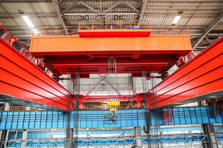
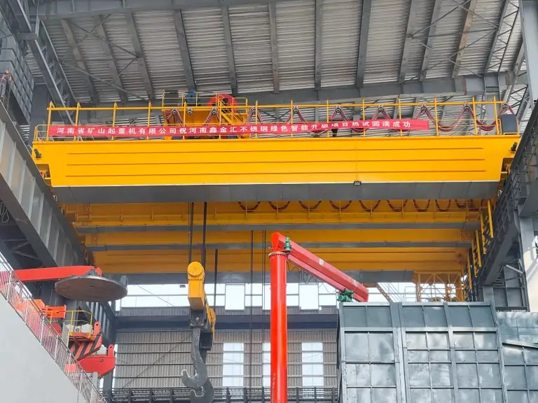
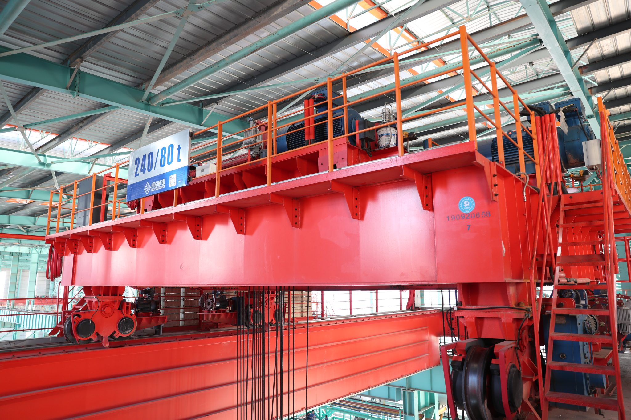
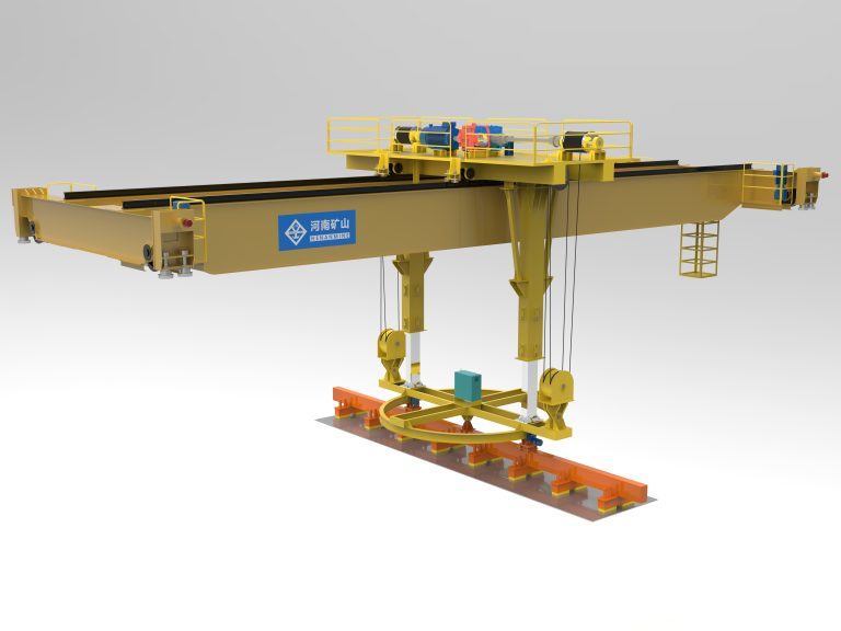
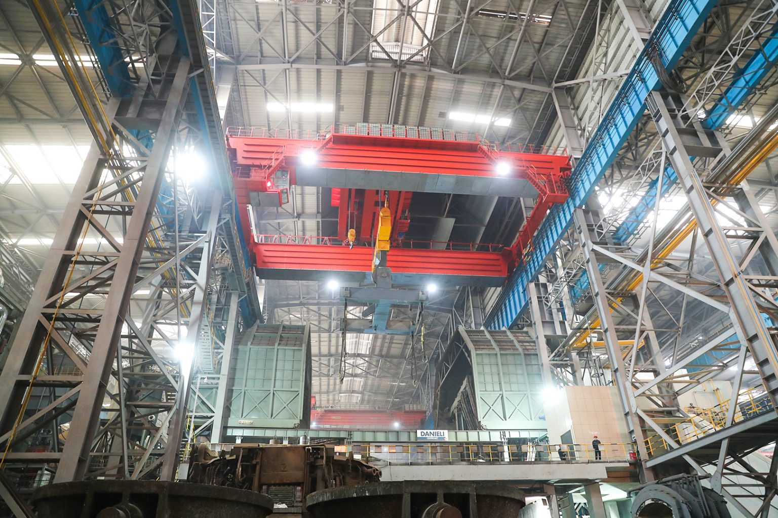
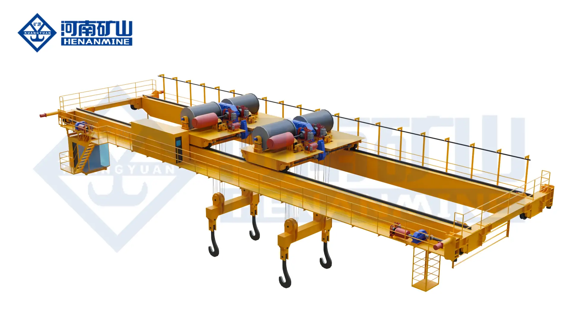
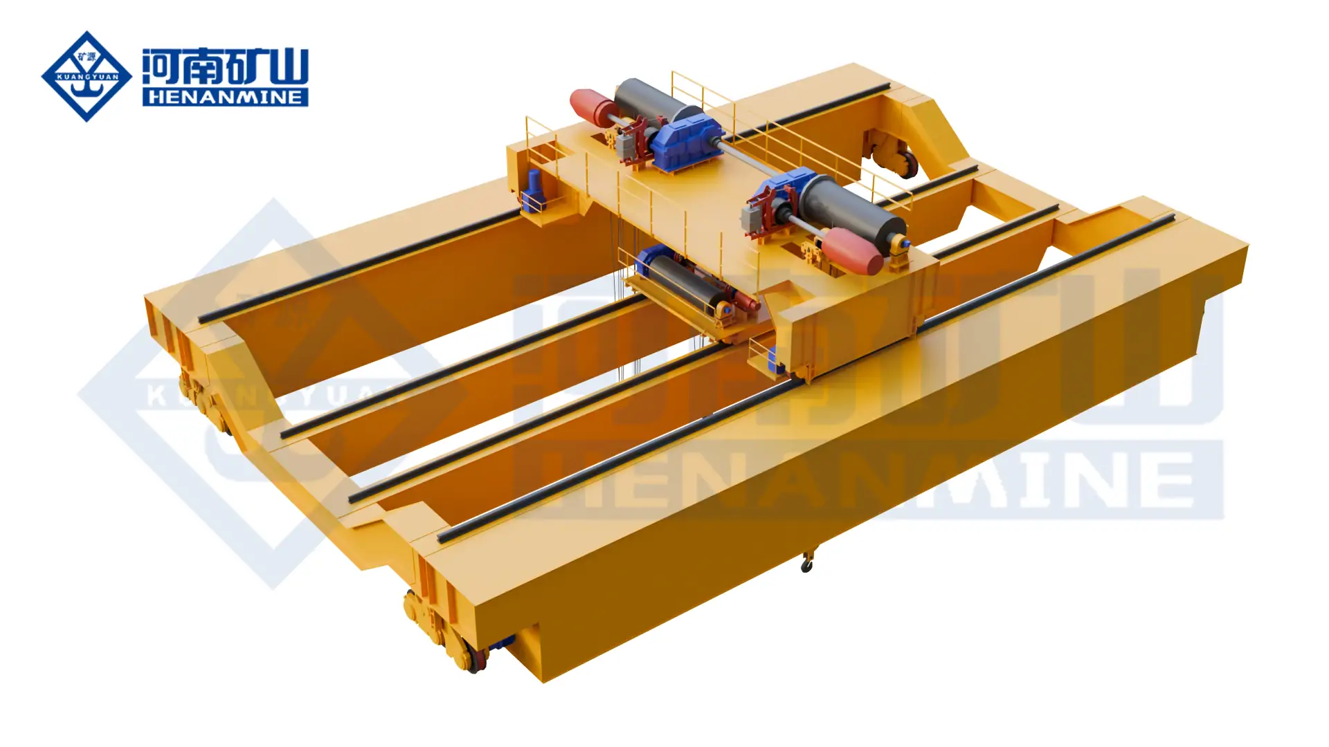
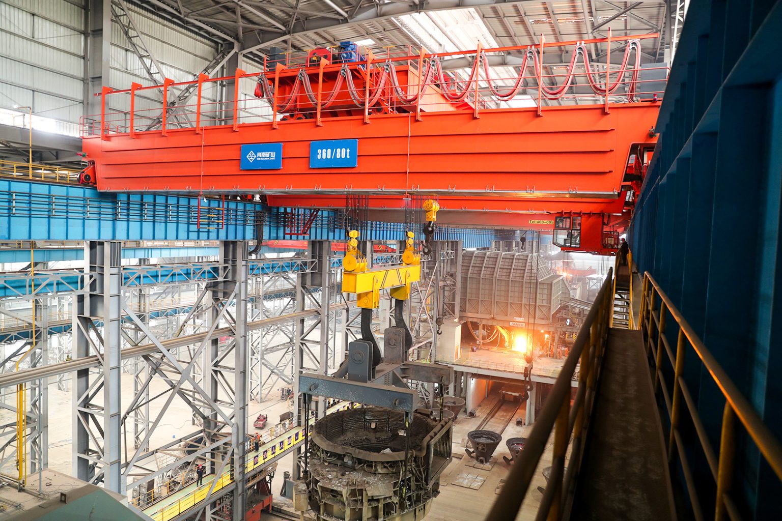
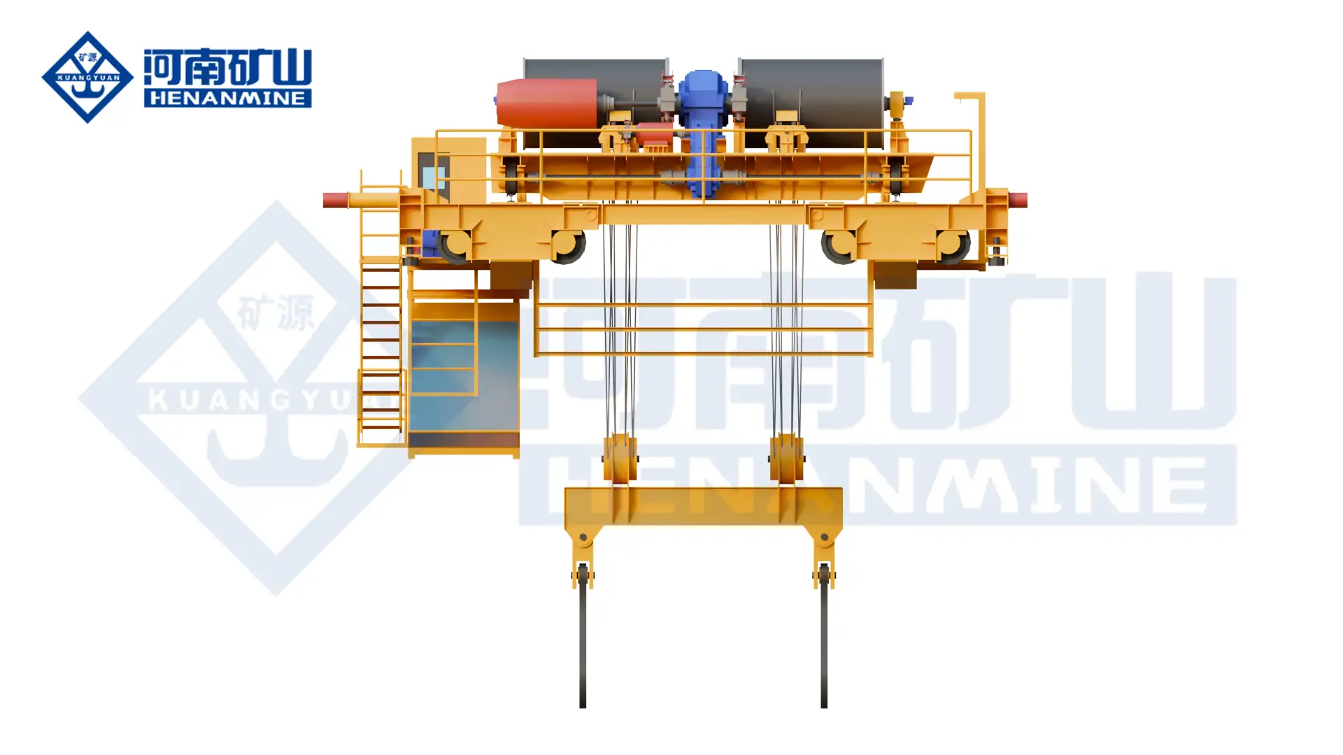
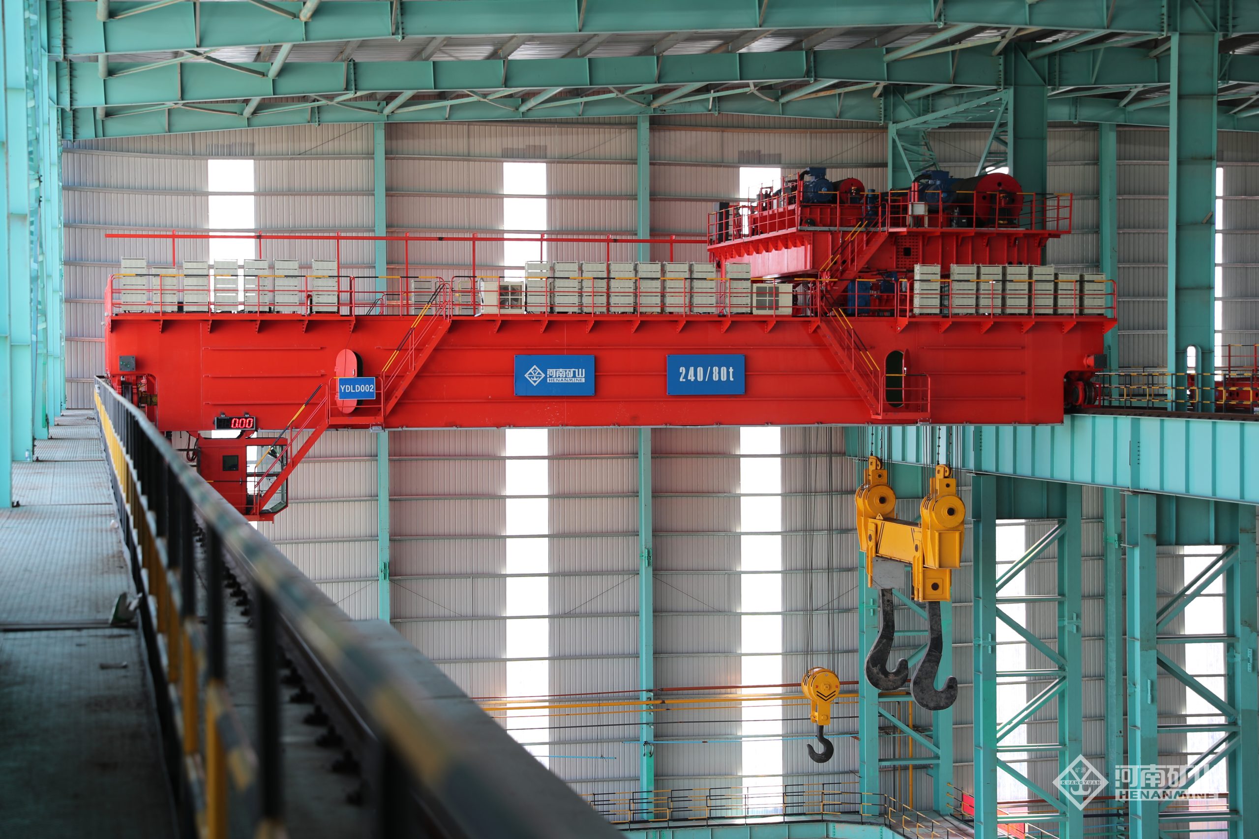
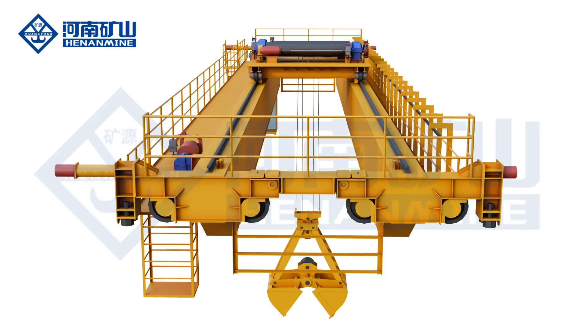
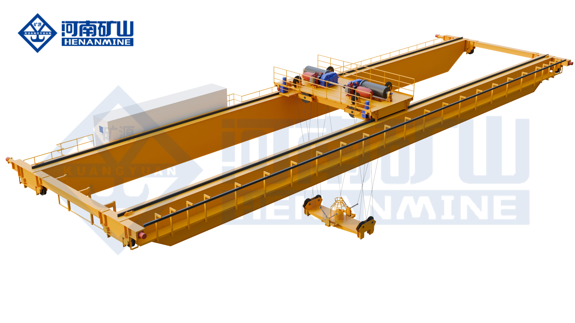
    galvanizing line crane for a hot-dip galvanizing workshop
    Galvanizing plants require application-specific lifting arrangements, corrosion protection, controlled motion and process interfaces.

    PROCESS AREAS

    Pretreatment, Zinc Kettle, Cooling & Finishing

    HANDLING DUTIES

    Transfer, Immersion, Tilting, Drainage & Maintenance

    DESIGN CONDITIONS

    Corrosive Fumes, Heat, Moisture & Cyclic Duty

    PRICE BASIS

    Engineered Project Quotation

    What Is a Galvanizing Line Crane?

    A galvanizing line crane is an overhead process crane engineered to move steel products, racks, baskets or crossbeams through batch hot-dip galvanizing operations. It may execute loading, tank-to-tank transfer, controlled immersion, dwell, withdrawal, drainage, cooling and unloading. Its motions can form part of the production recipe, so the crane must be specified as process equipment rather than as a general workshop lifting machine.

    A galvanizing facility may require several distinct crane duties: one or more production-line cranes for the chemical tanks and zinc kettle, a loading or finishing crane outside the aggressive process zone, and a separate maintenance crane for the kettle, furnace equipment, lifting beams and removable plant components. Combining incompatible duties without a route, availability and environmental review can restrict production or create an unsuitable protection concept.

    Capacity, span and lifting height are only the starting parameters. A procurement specification also requires the complete suspended mass, workpiece geometry, lifting-point arrangement, tank coordinates, immersion angle, process speeds, cycle histogram, chemical and thermal exposure, automation interfaces, safe-recovery philosophy and responsibility boundary.

    Galvanizing Line Crane Types

    01 · Single-Girder Process Crane

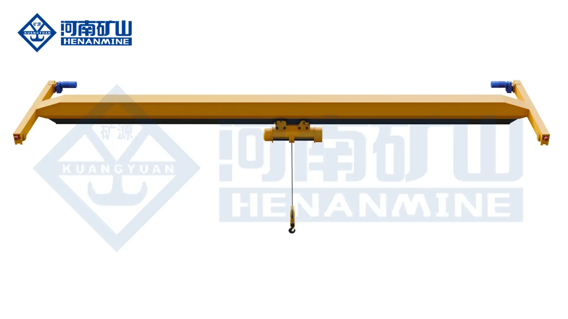
    A compact bridge with one or two hoists for moderate suspended loads, shorter spans and defined production cycles. Hoist synchronization, service access, corrosion protection and the required duty class must be verified before selecting this lower-self-weight arrangement.

    02 · Double-Girder Process Crane

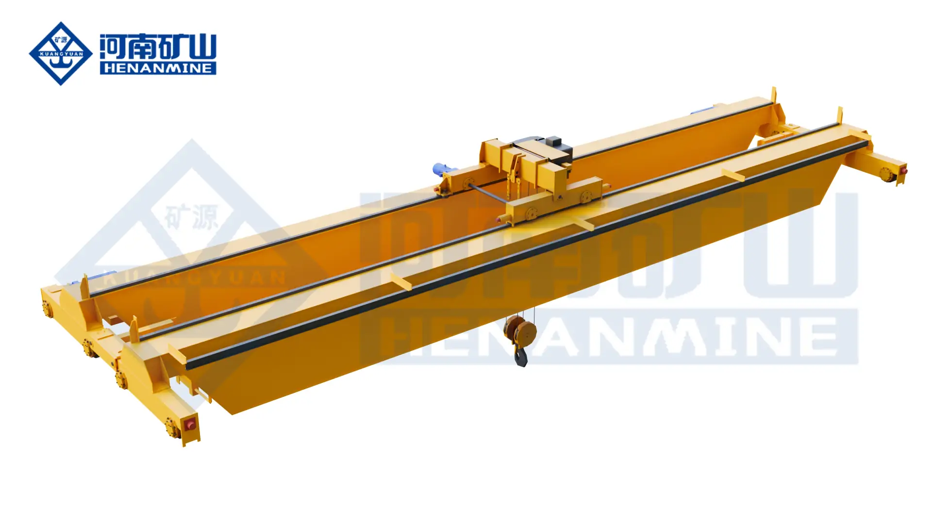
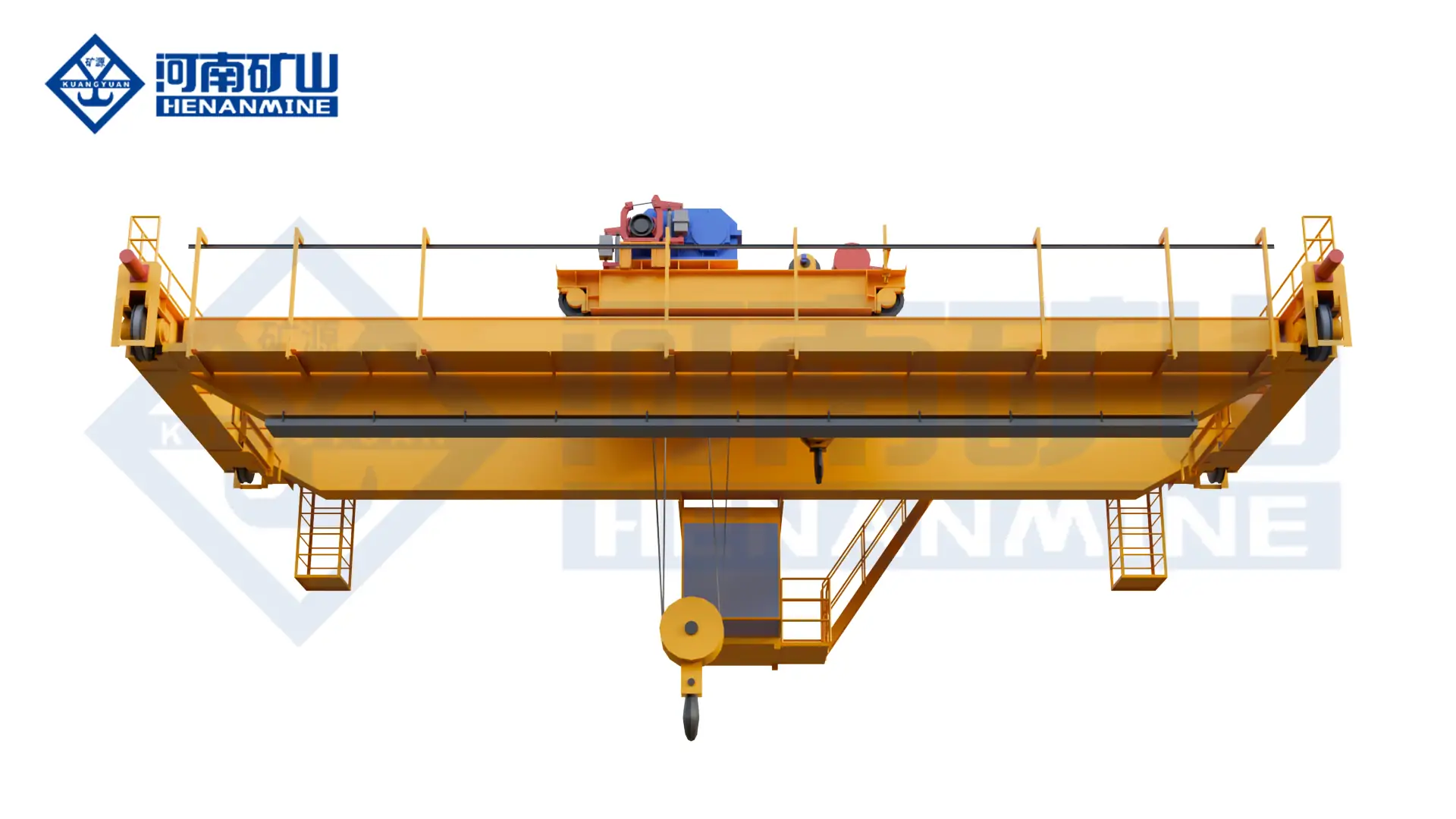
    A robust platform for longer spans, frequent cycles, higher suspended loads, service walkways and process-specific trolley arrangements. It provides greater flexibility for automation, redundant positioning feedback and maintainable component layouts.

    03 · Twin-Hoist or Twin-Trolley Crane

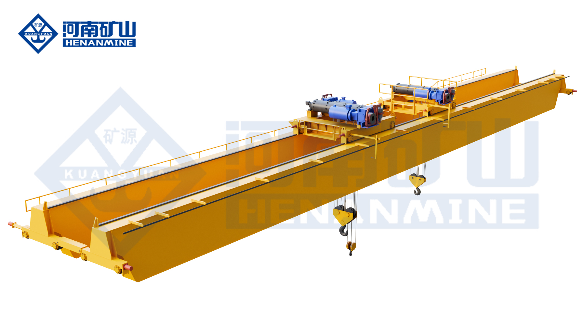
    Two lifting points stabilize long workpieces and support controlled entry, withdrawal and drainage angles. The control system defines synchronized lifting, permitted differential height, restricted independent motion and fault recovery.

    04 · Automated Galvanizing Transport System

    One or more cranes execute recipe-based routes using position feedback, tank handshakes, inter-crane zoning, production tracking and controlled recovery modes. The crane, line PLC and supervisory-system boundaries are defined before quotation.

    05 · Cantilever Zinc-Pot Crane

    A project-defined cantilever extends hook coverage beyond the normal bridge envelope for empty-pot handling, furnace-area service and equipment maintenance. It is not automatically a substitute for the production transport crane.

    06 · Loading, Finishing and Maintenance Crane

    A single- or double-girder overhead crane for racking, unloading, inspection, component removal and workshop service. Environmental protection is selected for its actual zone, while process-crane features are included only when the duty requires them.

    Compare Galvanizing Line Crane Configurations

    The correct configuration follows the workpiece, process route, immersion method, cycle demand and exposure zone. Cranes with the same rated capacity may have different hoist arrangements, controls, protection systems and commercial scope.

    Crane Configuration Primary Duty Lifting Arrangement Critical Design Basis Not a Substitute For
    Single-Girder Process Crane Moderate-load process transfer on a defined line One or two electric hoists with project-specific beam or rack interface Span, duty, synchronization, headroom, environment and maintenance access High-cycle automated systems without a complete engineering review
    Double-Girder Process Crane Frequent cycles, longer spans, higher loads and automation Top-running trolley with single, twin or process-specific hoisting Cycle histogram, wheel loads, service access, motion control and plant interfaces A lower-cost general crane selected only by capacity
    Twin-Hoist or Twin-Trolley Crane Long-load stabilization, tilting and controlled drainage Two lifting points operating synchronously or within a restricted differential Load stiffness, lifting-point spacing, maximum angle, feedback and fault response Independent uncoordinated hoists without load-control logic
    Cantilever Zinc-Pot Crane Pot replacement, furnace maintenance and extended hook coverage Project-defined cantilever with hook or maintenance lifting beam Component weights, outreach, headroom, structural forces and service procedure Automatic tank-to-tank production transport
    Integrated Multi-Crane System High-throughput lines, parallel tanks and separated process zones Multiple coordinated cranes, transfer points and buffer stations Route simulation, collision zones, queue logic, availability and recovery strategy A single-crane layout where production continues after one machine stops

    Selection principle: define the crane from the complete process duty. A general overhead crane does not become a galvanizing process crane by adding corrosion-resistant paint, and two standard hoists do not provide controlled tilting without the required synchronization, permissions and fault response.

    Match the Crane to the Galvanizing Process Area

    A plant-wide handling study records every pickup point, tank coordinate, dwell time, travel route, attachment, restricted zone and line interface. It also separates loading, production and maintenance duties that cannot share one machine because of environmental exposure, incompatible working envelopes or required availability.

    For the pretreatment tanks, the study addresses corrosive vapor, liquid carryover, drainage, tank-rim clearance and fume-extraction interfaces. For molten-zinc immersion, it defines slow process speed, load angle, withdrawal profile, drip route, heat exposure, cover permissions and the safe position for abnormal recovery.

    Loading, cooling and unloading areas require stable handover, product identification and safe interaction with operators. Pot replacement and furnace maintenance require a separate component-weight schedule, removal route, outreach, shutdown plan and verified set-down points.
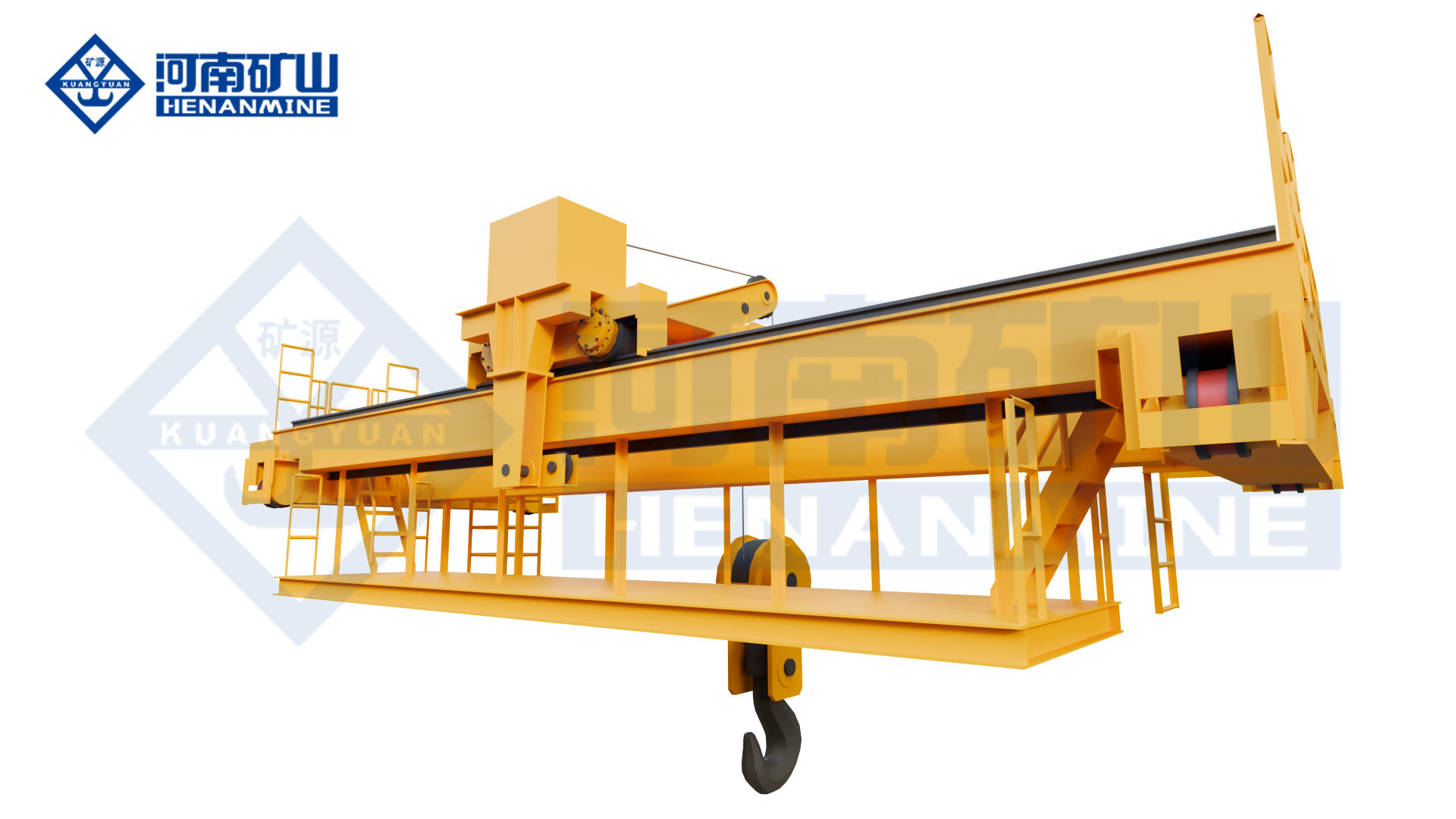
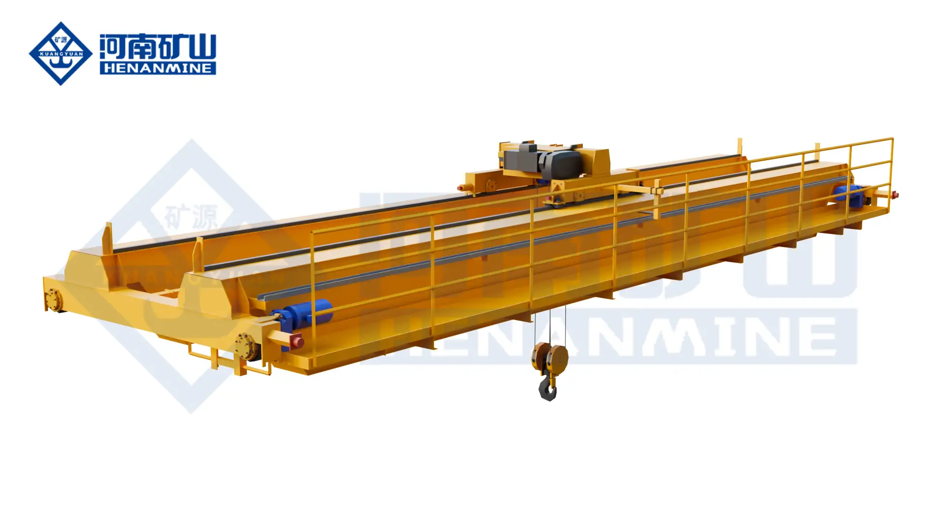
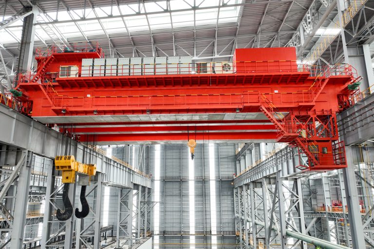
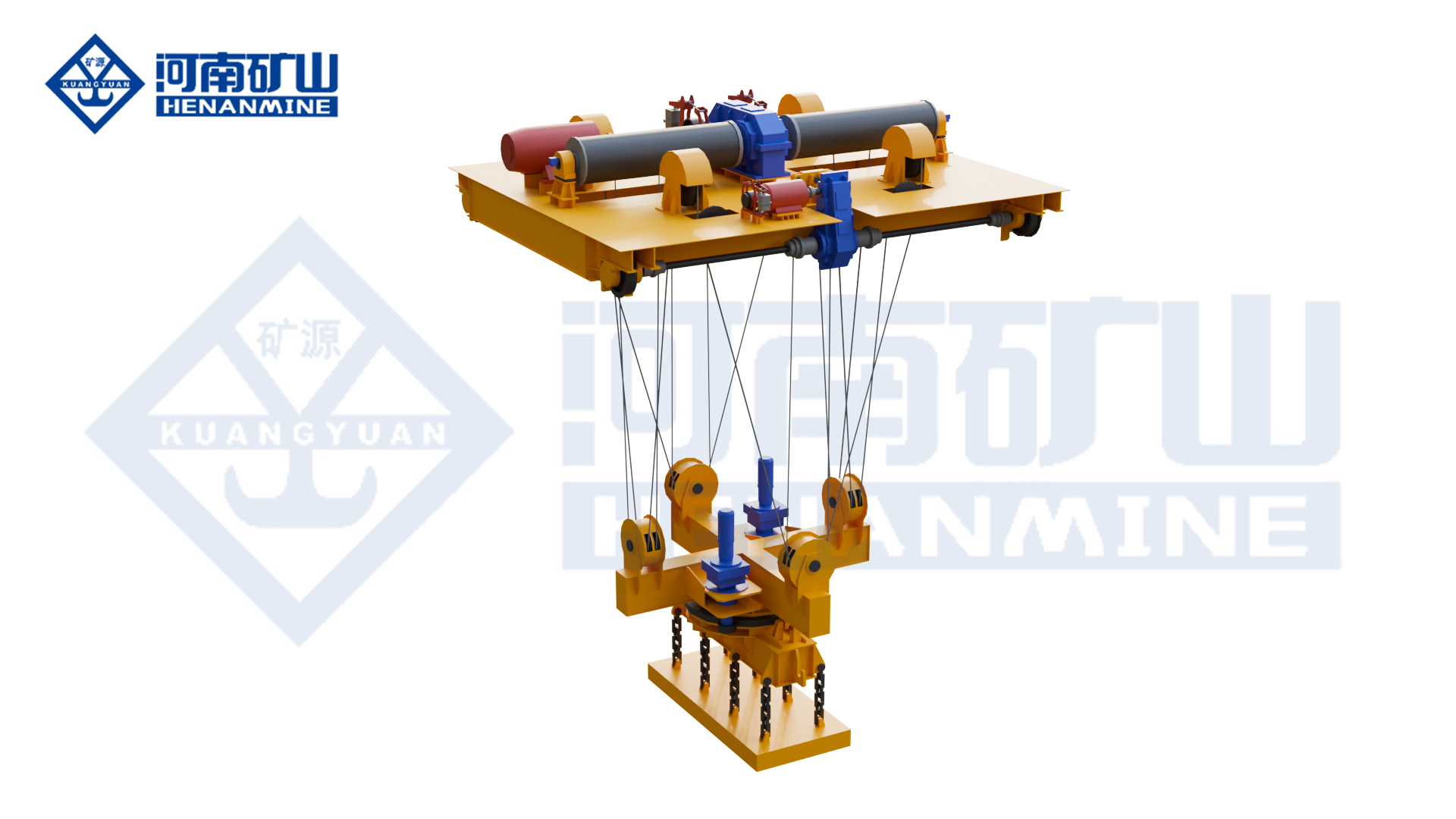
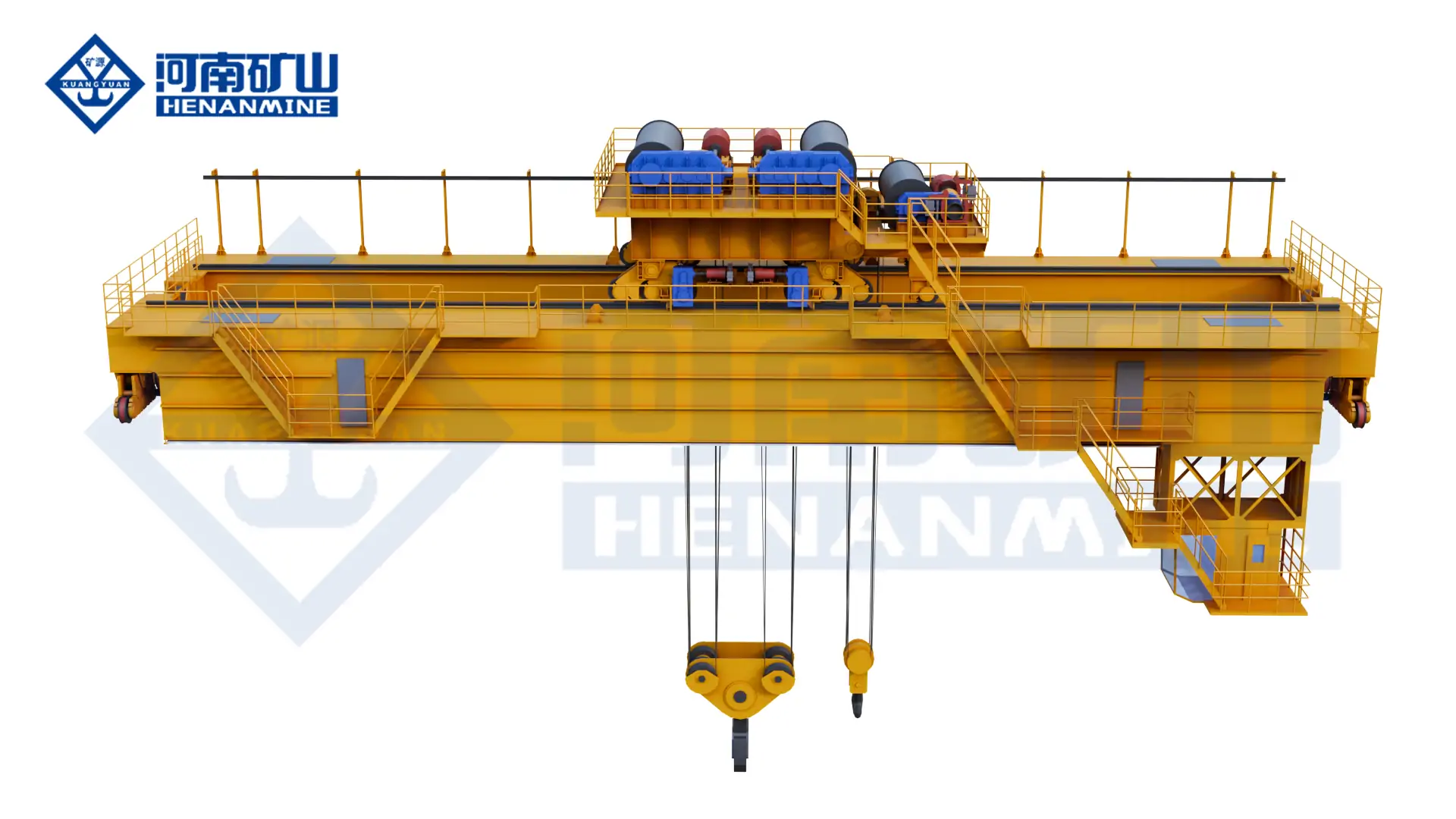
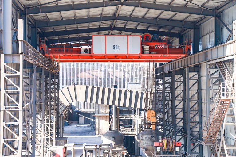
    special overhead crane configuration for a galvanizing process area
    The crane envelope, hoist arrangement and attachment interface are coordinated with the tank line, kettle and fume-control equipment.
    Process Area Handling Task Crane Starting Point Essential Project Data
    Loading and Racking Pick up prepared jigs, baskets or crossbeams Loading crane or first process crane Load geometry, lifting points, identification and handover method
    Degreasing, Rinsing and Pickling Lower, dwell, lift, drain and transfer between tanks Corrosion-protected process crane Chemicals, vapor, tank layout, liquid carryover and extraction
    Fluxing and Drying Maintain process sequence and transfer toward the kettle Process crane with station interlocks Dwell time, dryer interface, queue logic and permissible route
    Molten-Zinc Immersion Controlled entry, immersion, withdrawal and drainage Twin-hoist or purpose-built process crane Angle, slow speed, differential height, heat, fumes and recovery
    Cooling and Finishing Transfer hot galvanized loads to inspection and unloading Process or finishing crane Temperature, drip route, clearance, tracking and handover
    Kettle and Plant Maintenance Remove empty pots, furnace parts, beams and equipment Independent maintenance or cantilever crane Component schedule, outreach, removal route and shutdown plan

    Technical Selection and Specification Framework

    A procurement specification should convert production requirements into measurable crane performance and assign every building, process and control interface. Each hoist, trolley, lifting beam or process tool may require a separate capacity, speed, duty and acceptance criterion.

    Specification Item Required Project Input Engineering Output Risk if Undefined
    Rated Load and Load Case Workpiece, rack, crossbeam, chains, hooks, retained liquid or zinc and center of gravity Rated loads by mechanism, load combinations, overload settings and structural basis Undersized equipment or unnecessary capital cost
    Span, Runway and Clearances Rail centers, runway length, elevations, tank rims, covers, ducts and allowable wheel loads General arrangement, approaches, wheel-load schedule and interference study Building conflict, reinforcement or delayed installation
    Immersion and Drainage Profile Entry angle, lowering speed, dwell, withdrawal speed, drain angle and safe position Hoist arrangement, differential limits, VFD range, feedback and motion profile Poor coating flow, load instability or tank-rim contact
    Duty and Availability Route variants, loads per hour, dwell times, shifts, annual hours and standby philosophy Crane classification, motor thermal checks, speeds, fleet quantity and maintenance plan Premature wear, queue growth or production stoppage
    Environment and Protection Chemicals, vapor concentration, humidity, condensation, temperatures, fumes and wash-down Materials, coating, sealing, enclosure, heating, cooling, cable and sensor selection Corrosion, overheating, unreliable controls or shortened life
    Control and Automation Manual tasks, recipes, positioning, station signals, line PLC, network and data ownership Operating modes, permissions, interlocks, HMI, communications and recovery logic Scope gaps between crane, line and plant-control suppliers
    Compliance and Acceptance Destination law, purchaser standard, area classification, witness points and trial material Code matrix, inspection plan, FAT, load tests, SAT and process-trial criteria Repeated tests, unclear compliance or contractual dispute

    Protection, Controls and Safety for Galvanizing-Line Conditions

    Controlled Immersion and Drainage

    Variable-frequency hoisting, slow process speed, position feedback and defined approach zones support controlled entry and withdrawal. Twin lifting points require permitted differential height, maximum angle and a documented recovery sequence.

    Chemical and Corrosion Protection

    Coating systems, protected cavities, corrosion-resistant hardware, sealed bearings, suitable ropes or chains, cable materials and maintainable inspection points are selected from the measured exposure in each process zone.

    Heat and Fume Exposure

    Heat shields, equipment separation, protected cable routing, ventilation and component temperature ratings are coordinated with the dryer, kettle, enclosure and extraction system rather than assigned from a generic ambient temperature.

    Electrical and Control Protection

    Enclosures, anti-condensation heating, protected electrification, control cabinets and network hardware are located and rated for the verified humidity, vapor and temperature. Explosion protection is supplied only where formal area classification requires it.

    Load, Motion and Collision Safety

    Overload limiting, brakes, operating and final limits, attachment confirmation, buffers, anti-derailment measures, fixed-obstacle zones, inter-crane separation and tank-occupancy logic form one coordinated protection architecture.

    Access, Isolation and Acceptance

    Guarded access, maintenance platforms, isolators, lockout provisions, emergency stops, safe-state logic and manual recovery are verified through functional tests, load tests, interlock trials and fault-recovery demonstrations.
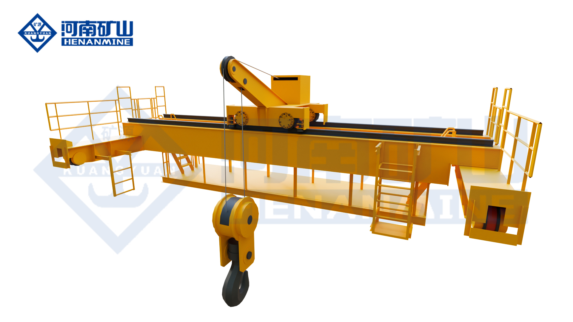
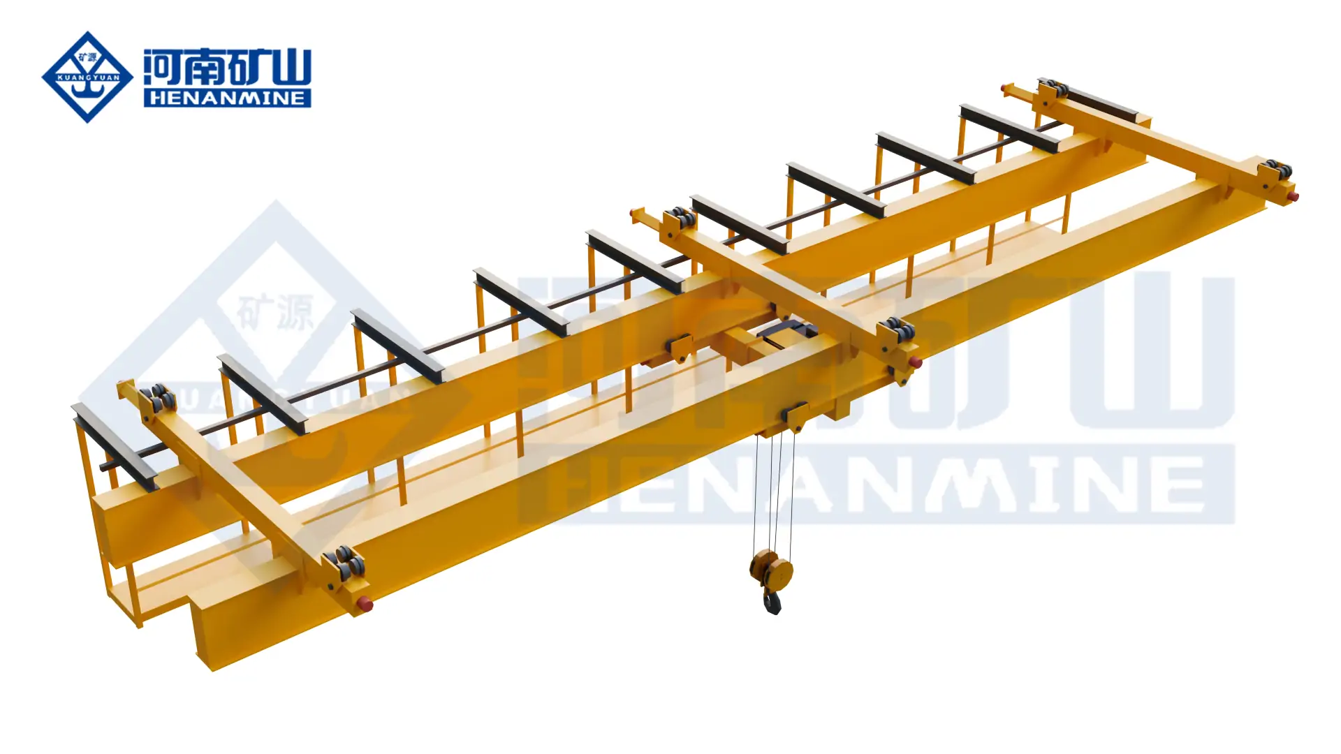
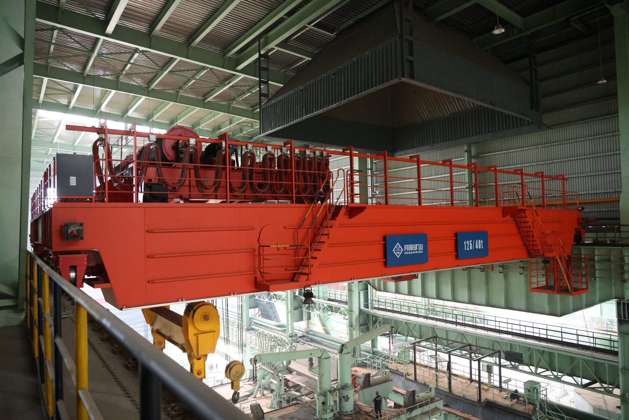
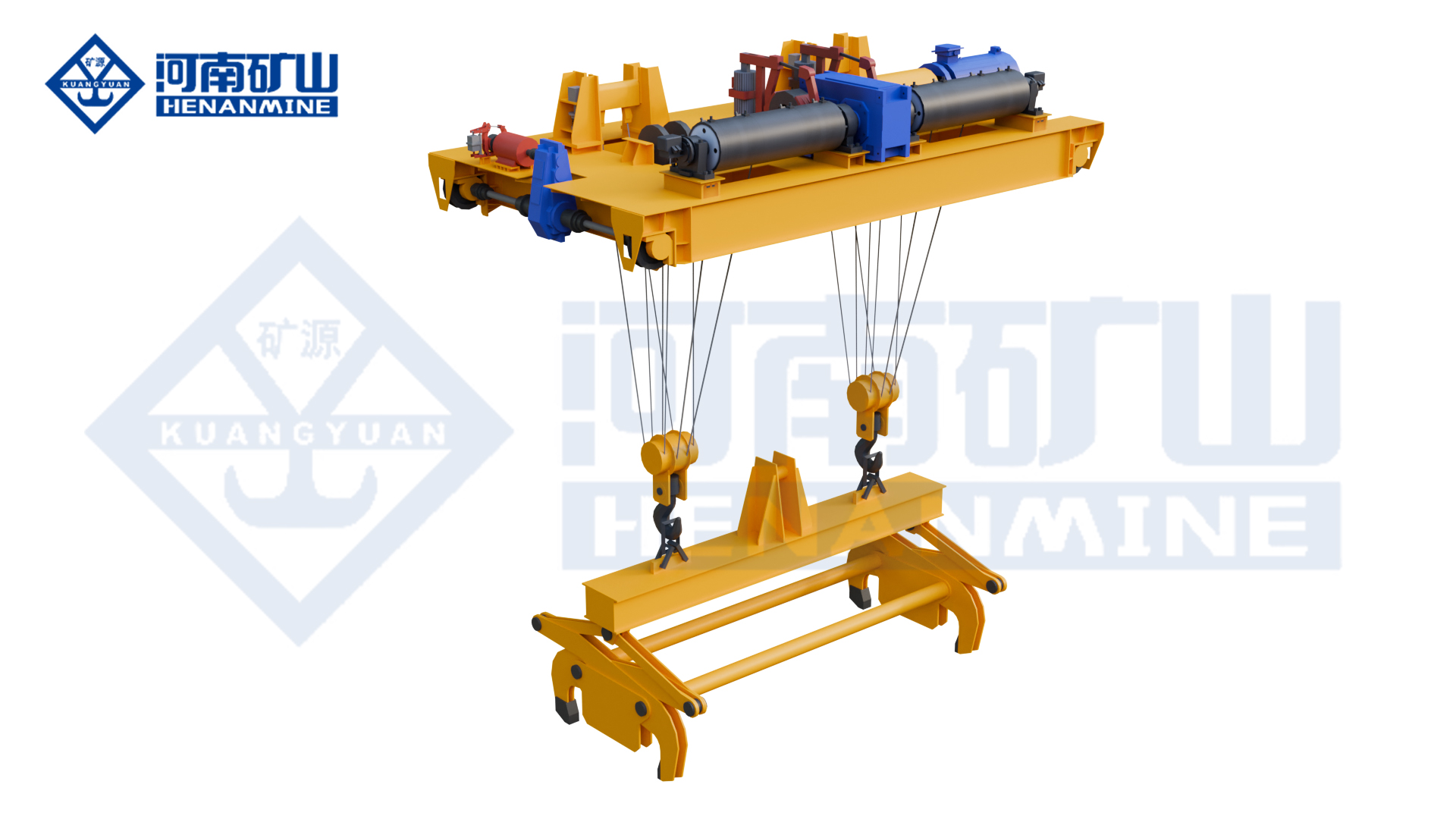
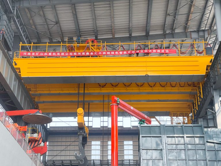
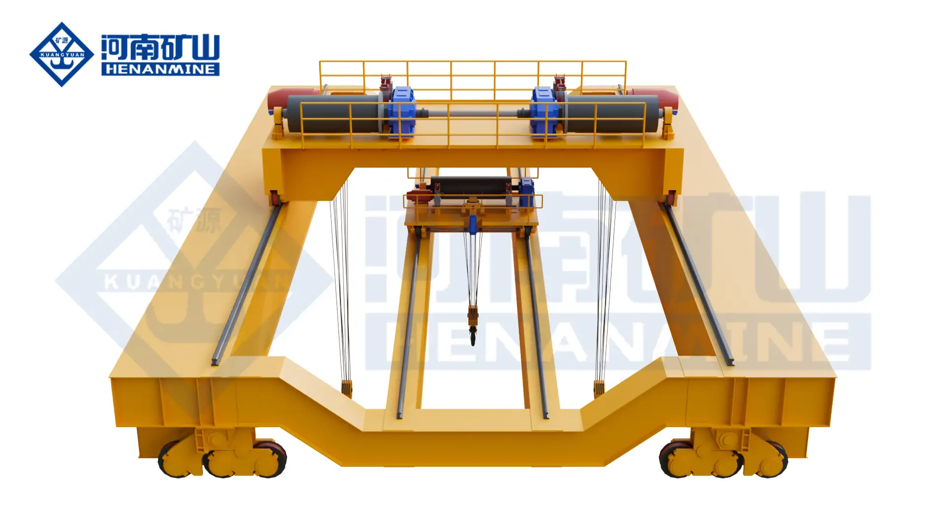
    galvanizing overhead crane configured for controlled process motion
    Position feedback, controlled motion and verified line interfaces support repeatable tank-to-tank handling.

    Galvanizing Line Crane Automation and Process Integration

    Manual, assisted, semi-automatic and fully automatic operating concepts are available. The correct level depends on product variety, route stability, required throughput, tank demand, operator-access restrictions, traceability and the production consequence of a crane becoming unavailable.

    An automated system can manage product identification, recipe association, station sequence, dwell time, approach speed, immersion and withdrawal profiles, drain position, crane separation, buffer priority and alarm history. Tank-ready signals, covers, extraction status, doors and attachment confirmation can be used as process permissions.

    The quotation should define the boundary between crane PLC, line PLC, supervisory system, tank equipment, extraction system and production database. Signal lists, network protocols, safe states, manual overrides and restart procedures must be agreed before software development and factory testing.

    Henan Mine Crane Galvanizing Crane Configuration

    Galvanizing Pot and Maintenance Crane

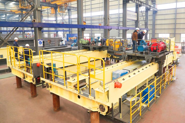
    Henan Mine Crane configures galvanizing special overhead cranes for zinc-pot handling, equipment maintenance and high-temperature workshop service. The available design range includes 5–32 t rated capacity, 10.5–31.5 m span, 6–24 m lifting height, A5–A6 working class, 220–690 V at 50/60 Hz and crane travel speeds of 8–40 m/min, subject to final project engineering.

    The crane can be configured with a single- or double-girder structure and a project-defined cantilever to extend vertical hook coverage outside the normal bridge envelope. Variable-frequency motion, overload protection, travel limits, emergency braking and anti-derailment provisions are incorporated according to the final design.

    These values define an available design range, not an automatic specification for every galvanizing line. A crane that carries workpieces through chemical tanks and molten zinc requires an independent review of synchronized lifting, process cycle, attachments, corrosion zones, automation interfaces and safe recovery.
    View Galvanizing Special Overhead Crane →

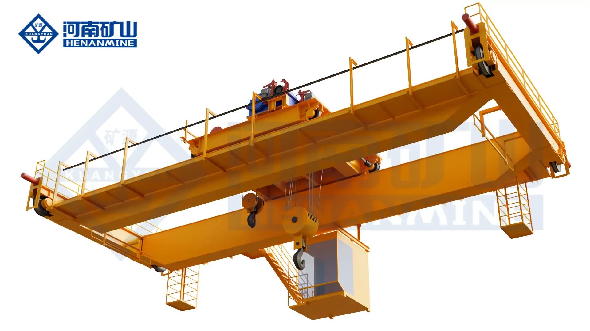
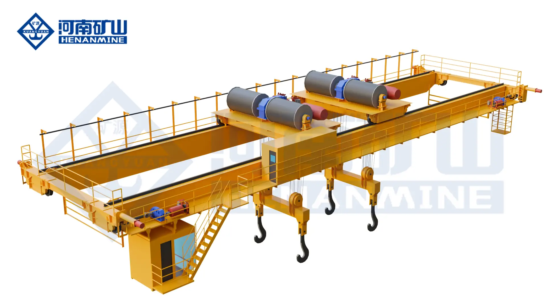
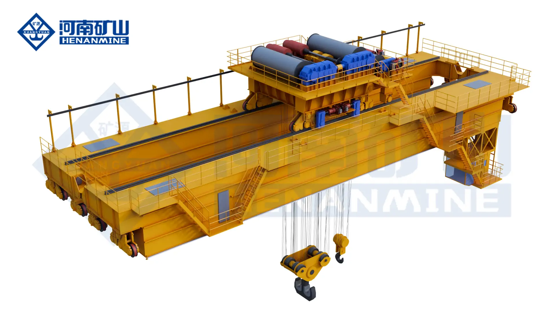
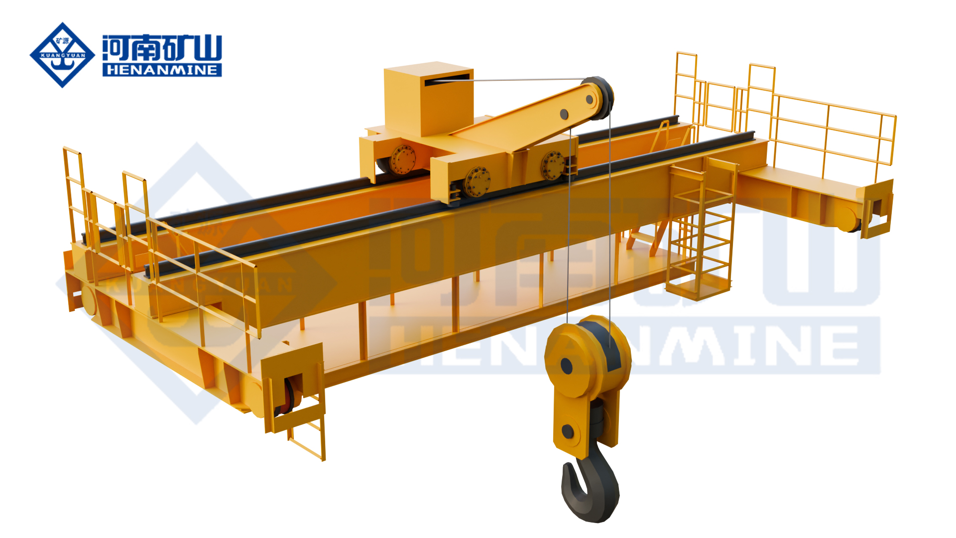
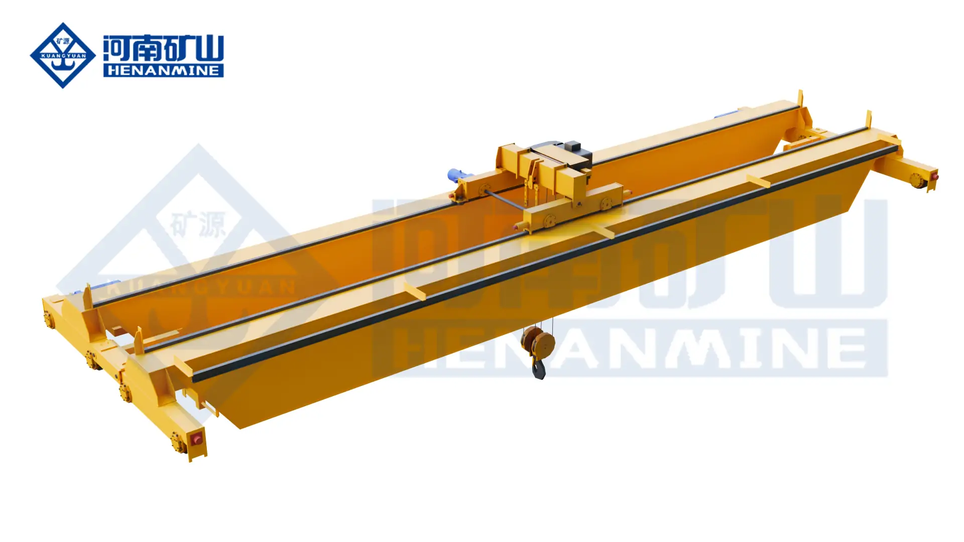
    Henan Mine Crane galvanizing pot maintenance overhead crane
    Project-defined bridge and cantilever arrangement for zinc-pot service and galvanizing-workshop maintenance coverage.

    Engineering Deliverables and Quality Records

    A procurement-ready proposal defines crane performance, process and building interfaces, inspection, acceptance and site responsibilities. Documents remain traceable from approved inputs through manufacturing, factory testing, installation and commissioning.

    Design Basis

    Approved load schedule, process route, duty calculations, general arrangement, lifting-device envelope, wheel loads, exposure zones, code matrix and responsibility boundary.

    Control Documentation

    Electrical diagrams, PLC and network architecture, operating modes, I/O schedule, interlock matrix, alarms, safe states, recovery logic and plant communications.

    Manufacturing Records

    Material traceability, welding procedures, welder qualifications, dimensional inspection, NDT, machining checks, coating reports and component certificates as contracted.

    Factory Acceptance

    Drive, brake, limit, overload, alarm and interlock tests; synchronized-hoist functions; control modes; communications; simulated recipes and purchaser witness points.

    Review Henan Mine Crane manufacturing and quality capabilities →

    Installation, Commissioning and Lifecycle Planning

    Site Readiness

    Confirm runway survey, rail elevation, building reserve, erection route, tank and kettle coordinates, extraction interfaces, power, network, access controls and shutdown windows.

    Installation

    Bridge and trolley assembly, rail and conductor checks, lifting-device integration, sensor alignment, control cabinets, utilities and line-network connections follow approved method statements.

    Commissioning

    Testing progresses from no-load motion and safety devices to proof testing, positioning calibration, synchronized lifting, signal checks, dry recipe simulation and controlled process trials.

    Lifecycle Support

    Training covers operation, attachment handling, isolation, alarms and recovery. Preventive maintenance addresses mechanisms, controls, electrification, coatings, enclosures and sensors exposed to the process environment.

    Galvanizing Line Crane Price and Supply Scope

    A purpose-built galvanizing line crane is priced against an approved technical scope. Capacity, span and lifting height affect the equipment cost, but the hoist arrangement, workpiece attachment, corrosion protection, process motion, automation, runway interface, delivery boundary and site services determine whether quotations are technically comparable.

    Quotation Level Typical Included Scope Principal Cost Drivers
    Loading or Finishing Crane Bridge, hoist or trolley, standard controls and defined attachment interface Capacity, span, lift height, duty, headroom and environmental protection
    Galvanizing Process Crane Process hoists, lifting beam interface, VFD motion, corrosion protection, positioning and tank interlocks Cycle demand, twin-hoist control, immersion profile, protection zones and process interfaces
    Automated Multi-Crane System Multiple cranes, route control, collision management, recipe handling, production tracking and plant communication Crane quantity, throughput, redundancy, software boundary, signal count and trial scope
    Zinc-Pot Maintenance Crane Bridge and cantilever structure, maintenance hoist, access, high-temperature protection and dedicated tooling Maximum component load, outreach, removal route, structural reactions and shutdown requirements

    A valid commercial comparison requires the same technical data sheet, lifting-device boundary, automation responsibility matrix, inspection plan, delivery term and site-service scope. A lower equipment-only price may exclude essential process functions or transfer substantial cost and risk to the purchaser.

    Crane Equipment

    Bridge, trolleys, hoists, motors, brakes, wheels, platforms, access and power collection.

    Process Handling

    Crossbeams, racks, baskets, chains, synchronized lifting, tilting and attachment confirmation.

    Protection and Controls

    Coatings, sealed components, VFDs, PLC, positioning, interlocks, sensors and plant communications.

    Project Services

    Engineering, documents, FAT, packing, freight, installation, commissioning, trials and training.

    Information Required for a Galvanizing Line Crane Quote

    A complete inquiry allows the crane configuration, process interfaces, delivery scope and commercial exclusions to be evaluated together. Preliminary drawings are acceptable during concept design when unresolved values are clearly identified.

    01 · Plant and process scope

    New line, expansion or modernization; loading, pretreatment, kettle, cooling, finishing or maintenance duty; required throughput and crane role.

    02 · Building and runway

    Layout, sections, rail span, runway length, elevation, headroom, end approaches, rail data, building capacity and allowable wheel loads.

    03 · Loads and attachments

    Workpiece range, racks, baskets, crossbeams, chains and hooks; maximum suspended mass, dimensions, center of gravity and lifting points.

    04 · Tank line and handling route

    Tank and kettle coordinates, covers, ducts, pickup and discharge points, route variants, buffers, obstacles and restricted zones.

    05 · Process performance

    Immersion and withdrawal profile, drain angle, dwell times, speeds, positioning accuracy, cycles, shifts and availability target.

    06 · Environmental conditions

    Chemicals, concentrations, vapor, humidity, condensation, temperatures, fumes, wash-down, altitude and area classification.

    07 · Controls and interfaces

    Manual or automatic modes, recipes, line PLC, supervisory system, network protocol, covers, doors, extraction and station sensors.

    08 · Power, standards and acceptance

    Voltage, frequency, destination, governing crane and electrical standards, inspection authority, FAT, load test and process trials.

    09 · Delivery and site scope

    Destination, trade term, packing, freight, runway, electrification, installation, commissioning, local labor, training and production support.

    10 · Schedule and lifecycle

    Required delivery date, shutdown window, documentation language, recommended spares, maintenance capability and service expectations.

    Galvanizing Line Crane FAQ

    Can a standard overhead crane be used on a galvanizing line?

    A general crane may serve a clean loading or maintenance area after verification, but a process crane requires protection and controls selected for chemicals, humidity, heat, fumes, cycle frequency, attachments and immersion movements.

    How is the required crane capacity calculated?

    Use the maximum combined mass of the workpiece, rack or crossbeam, chains, hooks, lifting devices and retained process liquid or zinc, then apply the required engineering and regulatory allowances.

    Why are two hoists used on some galvanizing cranes?

    Two lifting points can stabilize long loads and permit a controlled entry, withdrawal and drainage angle. The controls must define synchronized operation, permitted differential height and fault response.

    Is full automation necessary?

    No. Manual control suits flexible or lower-output plants, semi-automation provides controlled station movements, and full automation is appropriate where repeatable recipes, throughput and restricted access justify the integration.

    What corrosion protection is required?

    The protection system depends on measured exposure by zone. It may include specialized coatings, sealed components, corrosion-resistant hardware, protected electrification, anti-condensation measures and remote control cabinets.

    Does a galvanizing line crane need explosion protection?

    Only where a formal hazardous-area classification and applicable local standard require it. The process and chemicals should be reviewed by the plant designer before electrical equipment is specified.

    Can the crane communicate with the galvanizing line PLC?

    Yes. The project can include station requests, tank-ready signals, cover and extraction status, job identification, recipe data, alarm exchange and production tracking through an agreed protocol.

    What determines the number of cranes?

    The answer depends on route timing, dwell times, simultaneous tank demand, crane travel distances, queues, maintenance strategy and the production impact of one crane becoming unavailable.

    Why do galvanizing line crane quotations vary widely?

    The supply may range from a bridge and hoist to a complete process system with synchronized lifting, attachments, corrosion protection, PLC control, line interfaces, documents, freight and site services.

    What should be demonstrated before final acceptance?

    Verify safety devices, load performance, positioning, synchronization, line interlocks, recipe sequences, alarms, manual recovery, fault recovery, documentation and operator-maintenance training.

    Request a Galvanizing Line Crane Proposal

    Submit the product and attachment data, tank-line drawing, maximum suspended load, production cycle, environmental information, control scope, destination standards and delivery location. Henan Mine Crane will prepare a project-specific technical and commercial proposal.
    Henan Mine CraneDiscuss your requirements ↗
  • Freestanding Bridge Crane

    Freestanding Bridge Crane

    Freestanding Bridge Crane

    Henan Mine Crane · Independently Supported Overhead Lifting System

    Freestanding Bridge Crane

    A freestanding bridge crane provides overhead lifting coverage on an independent floor-supported runway structure. The system is configured for industrial facilities where the existing building cannot carry crane reactions, where roof attachment is restricted, or where a defined production area requires its own lifting system.

    Henan Mine Crane develops the bridge, hoist, end carriages, runway beams, columns, bracing, electrification and project interfaces as one coordinated lifting system. Capacity, span, runway length, lifting height, working duty, column positions and foundation reactions are established for the individual application.

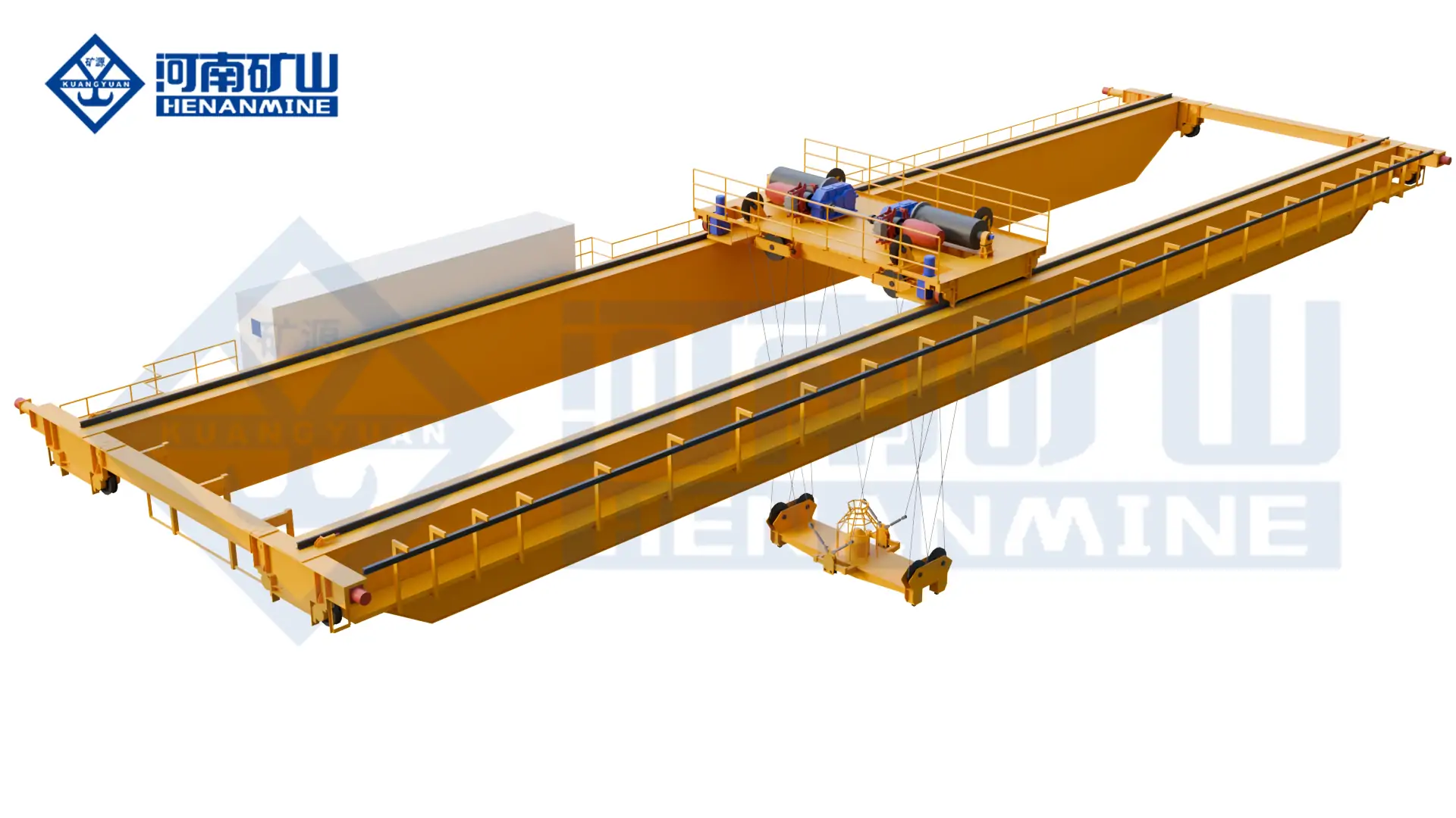
    Electric bridge crane equipment for a freestanding runway system
    Representative bridge crane equipment. Independent runway columns, bracing and foundations are defined in the approved project drawings.

    SUPPORT ARRANGEMENT

    Independent Floor-Mounted Runway

    WORKING COVERAGE

    Rectangular Crane Bay

    BRIDGE OPTIONS

    Single or Double Girder

    COMMERCIAL BASIS

    Project-Configured Quotation

    What Is a Freestanding Bridge Crane?

    A freestanding bridge crane is an overhead travelling crane carried by its own steel support structure rather than by the roof or primary columns of a building. Parallel runway beams are mounted on independent columns. The bridge travels along the runways, the hoist or trolley crosses the bridge, and the lifting mechanism raises and lowers the load. This movement provides longitudinal, cross-travel and vertical positioning across a defined working area.

    The structural load path runs from the lifted load through the hook, hoist, bridge girders, end carriages and rails into the runway beams, columns, bracing and foundations. Crane wheel reactions, horizontal forces and operating loads therefore require coordinated structural verification. A floor slab suitable for normal production traffic is not automatically suitable for crane-column reactions.

    Equipment definition: A freestanding bridge crane is a fixed overhead lifting installation. It is not a portable gantry crane. Relocation, extension or capacity changes require engineering review of the crane, steelwork, anchors, floor or foundations and revised operating clearances.

    Freestanding Bridge Crane Applications

    Production and Assembly Cells

    Dedicated lifting over machining, fabrication, assembly, testing and packing stations without transferring crane reactions into the building roof.

    Existing Industrial Buildings

    Facilities without an approved crane runway or with building steel that cannot accept the required vertical and horizontal crane loads.

    Warehousing and Maintenance

    Controlled handling of machinery, dies, components, maintenance assemblies and stored equipment across a rectangular service area.

    Leased or Adaptable Facilities

    Independent support can limit modifications to the main building, subject to permission for anchors, foundations, services and the complete installed structure.

    Crane Bays Inside Larger Workshops

    A defined lifting zone can operate below or beside other facility equipment when elevations, interferences and operating boundaries are coordinated.

    New Process Areas

    Independent runway systems for new production lines where crane coverage, column spacing and material flow can be planned together.

    Selection Considerations

    01 / LOAD

    Capacity and Load Geometry

    Rated capacity includes the lifted item and below-the-hook attachment. Load dimensions, centre of gravity, pickup method and potential side loading affect system design.

    02 / COVERAGE

    Hook Envelope and Approaches

    Runway gauge, bridge travel, hook approaches, lifting height and obstructions determine usable coverage rather than the outside steel dimensions alone.

    03 / STRUCTURE

    Columns, Bracing and Foundations

    Column spacing must suit equipment routes and floor activity. Base plates, anchors, bracing and concrete support are verified from crane reactions and site conditions.

    04 / DUTY

    Operating Cycle and Motion

    Lifts per hour, shifts, load spectrum, travel distance, positioning tolerance and process criticality establish mechanism duty and motion-control requirements.

    05 / CLEARANCE

    Headroom and Building Interfaces

    Roof steel, lights, ducts, doors, sprinklers, conveyors, racks and other cranes must remain outside the required structural and operating envelope.

    06 / ENVIRONMENT

    Site Conditions and Compliance

    Indoor or outdoor exposure, temperature, dust, corrosion, hazard classification, seismic conditions and applicable rules must be defined before configuration.

    Freestanding Bridge Crane Compared with Other Crane Configurations

    Configuration Support and Movement Selection Direction
    Freestanding Top-Running Bridge Crane Bridge wheels travel on rails above independently supported runway beams. Evaluated for industrial motorized systems requiring defined capacity, span, duty and lifting envelope.
    Freestanding Underhung Bridge Crane Bridge end trucks run from the lower flanges or dedicated track below the independent runway structure. Considered for lighter applications, workstation coverage or layouts suited to suspended bridge travel.
    Building-Supported Bridge Crane Runway loads transfer into approved building columns or roof structure. Reduces floor columns where the building is designed or verified for crane reactions and clearances.
    Gantry Crane The bridge is supported by legs that travel with the crane on floor rails, wheels or a defined route. Suitable where a moving leg structure is compatible with floor routes, outdoor yards or changing work zones.
    Monorail System A hoist travels along one fixed track with line-based coverage. Selected for a repeatable linear material route rather than full rectangular area coverage.
    Jib Crane A rotating boom provides local circular or sector coverage around one support. Suitable for one workstation where local rotation meets the handling route.

    Freestanding Bridge Crane Specifications

    A freestanding crane is defined by the approved crane schedule, runway arrangement and structural calculations. Final values are stated in the technical proposal and general arrangement drawing; capacity alone is not sufficient for equipment selection.

    Specification Engineering Direction Required Project Data
    Rated Capacity Project-defined for the selected crane and hoisting mechanism Maximum load, typical loads, attachment weight and load spectrum
    Span and Runway Length Matched to coverage, bridge structure and support spacing Runway gauge, travel distance, bay dimensions and required hook positions
    Lifting Height and Headroom Defined from hook travel, hoist arrangement and available top clearance Pickup level, placement level, rigging height and overhead obstructions
    Bridge and Runway Type Single or double girder; top-running or underhung as selected Capacity, span, duty, headroom, access and support geometry
    Independent Support Steel Runway beams, columns, base plates, anchors and bracing Column limits, floor plan, concrete data, soil or foundation data and seismic criteria
    Working Duty and Speeds Selected from operating frequency, load spectrum and process needs Lifts per hour, shifts, loaded cycles, travel distance and positioning tolerance
    Control and Power Pendant, radio or engineered control with site-matched electrical equipment Control preference, voltage, frequency, phases, earthing and power-feed location
    Operating Environment General industrial or purpose-configured environmental protection Temperature, humidity, dust, corrosion, wind, hazard classification and local requirements
    Double girder bridge crane for an independently supported runway
    Bridge arrangement, wheel loads and runway elevations are coordinated with the independent support steel.

    Runway Columns, Bracing and Foundations

    The support structure controls crane alignment, stability and load transfer. Runway beams and rails must maintain the geometry required by the bridge end carriages. Columns and bracing must resist vertical wheel reactions and the horizontal forces produced by travel, acceleration, braking, skewing and operating conditions.

    Column positions are coordinated with machines, aisles, vehicle routes, doors, storage and emergency access. Bracing locations must remain compatible with the working floor. Where cross-bracing would interfere with operations, an alternative structural arrangement may be evaluated within the applicable design limits.

    Foundation responsibility must be stated in the quotation. Existing slab thickness alone does not confirm adequacy. Concrete strength, reinforcement, slab condition, subgrade, anchor edge distances and calculated reactions must be reviewed by the responsible structural parties.

    Hook Coverage, Headroom and Facility Integration

    Usable Hook Coverage

    End approaches, trolley limits, conductor arrangements and physical end stops reduce hook coverage from the outside runway footprint. Required pickup and deposit points must be plotted before final sizing.

    Available Headroom

    Column height, runway elevation, bridge depth, hoist headroom and upper clearances establish the highest hook position. A low-headroom arrangement may require a different bridge or trolley configuration.

    Overhead and Floor Interfaces

    The crane envelope is coordinated with roof trusses, lights, sprinklers and services, while independent columns are coordinated with production equipment, racks, forklifts and pedestrian routes.

    Layout control: A dimensioned floor plan and building section provide the most reliable basis for crane geometry. The drawing package should identify runway gauge, rail level, overall support width, column spacing, hook approaches, lifting height, power-feed point and all fixed obstructions.

    Hoisting, Travel and Control System

    Hoisting Mechanism

    Electric chain hoists can suit selected light workstation duties. Wire-rope electric hoists or engineered trolley mechanisms are evaluated for industrial capacities, longer lifts, higher duty and process requirements.

    Bridge and Trolley Travel

    Manual movement may suit certain light enclosed-track systems. Motorized travel is configured where load, span, runway length, duty, production rate or positioning requirements make powered motion appropriate.

    Controls and Variable Speed

    Pendant or radio control can be specified. Variable-frequency control may support smoother acceleration, controlled approach, reduced load swing and more consistent positioning where the application requires it.

    Safety and Structural Coordination

    Safety functions and guarding are defined from the crane configuration, operating method, risk assessment and destination requirements. Final provisions are stated in the approved technical offer.

    Crane Protection

    • Upper and lower hoisting limits as specified
    • Overload protection for the selected hoisting arrangement
    • Travel end stops and buffers appropriate to the system
    • Emergency stop and electrical protective functions

    Runway and Support Control

    • Defined wheel reactions and horizontal design forces
    • Rail alignment, elevation and span tolerances
    • Column, bracing, base-plate and anchor verification
    • Foundation and concrete responsibility established by contract

    Operating Area

    • Clear separation from doors, racks and moving vehicles
    • Accessible inspection and maintenance positions
    • Control visibility matched to the load route
    • Site procedures for operation, isolation and inspection

    Freestanding Bridge Crane Supply Scope

    Proposal comparison requires a defined boundary for the crane, independent runway structure and site work. The final contract identifies included equipment, excluded work and interface responsibilities.

    Crane Equipment

    • Bridge girder or girders and end carriages
    • Hoist, trolley and selected controls
    • Crane electrification and travel components
    • Specified protection, limits, buffers and accessories

    Independent Runway System

    • Runway beams, rails and rail attachments
    • Columns, base plates and agreed bracing
    • Anchor bolts when included in the supply
    • Main power feed along the runway when specified

    Site and Project Services

    • Foundation design and construction as contractually assigned
    • Freight, unloading, erection and access equipment
    • Incoming electrical supply and site connections
    • Commissioning, testing and operator instruction as agreed

    Manufacturing, Inspection and Documentation

    Manufacturing begins after approval of the technical configuration, interfaces and commercial scope. Bridge and runway components are produced against the agreed drawing package, with material, fabrication, dimensional, mechanical and electrical controls assigned through the manufacturing plan.

    • General arrangement drawings and principal interface dimensions
    • Calculated crane reactions for structural coordination
    • Electrical diagrams and equipment information within the agreed package
    • Inspection and test records required by the contract
    • Operating and maintenance documentation for the supplied equipment

    Manufacturing facilities and production scenes are available in the Henan Mine Crane factory display.

    Industrial crane manufacturing workshop at Henan Mine Crane
    Industrial crane structure manufacturing and assembly at Henan Mine Crane.

    Installation, Commissioning and Maintenance

    01

    Site Verification

    Floor plan, elevations, concrete conditions, access routes, electrical services and obstructions are confirmed before installation.

    02

    Support Erection

    Columns, bracing, runway beams and rails are erected, aligned and secured to the approved foundation or concrete arrangement.

    03

    Crane Installation

    Bridge, hoist, power feed, controls and safety components are installed after runway geometry and access conditions are accepted.

    04

    Commissioning

    Functional checks, agreed tests, control verification and documentation support formal handover of the installed system.

    05

    Lifecycle Maintenance

    Inspection access, lubrication points, wearing parts, rail condition, anchors and structural connections are included in the maintenance plan.

    Freestanding Bridge Crane Price

    Freestanding bridge crane price depends on two connected scopes: the lifting equipment and the independent runway structure. Publicly listed U.S. light-workstation configurations available in September 2026 indicate approximately US$11,000–24,000 for selected 0.25–2 ton systems. These market budgets are not fixed Henan Mine Crane selling prices and are not equivalent to a complete industrial motorized bridge-crane project.

    Market Configuration Indicative Equipment Budget Commercial Interpretation
    Entry Light Workstation System Approximately US$11,000–14,000 Selected 0.25–1 ton standard bridge and runway dimensions; included hoist and services must be confirmed.
    Mid-Range Light Workstation System Approximately US$14,000–20,000 Selected longer runway or higher light-duty capacities, commonly up to 2 tons in standard workstation product lines.
    Extended Light Workstation System Approximately US$20,000–24,000+ Longer runway, bridge or specialized light-workstation arrangements; installation and site work may remain separate.
    Industrial Motorized Freestanding Bridge Crane Project quotation required Bridge, hoist, drives, runway beams, columns, bracing, foundations, electrification, freight and installation are defined individually.

    Price comparison rule: Equipment-only offers and complete installed systems cannot be compared as equal packages. A commercial review must confirm hoist inclusion, bridge and runway lengths, support steel, anchors, foundation work, power feed, freight, unloading, erection, commissioning, testing, taxes and destination compliance.

    Information Required for a Freestanding Bridge Crane Quotation

    A dimensioned layout and complete operating data support accurate crane selection, runway engineering and commercial scope definition.

    Load and Operation

    • Maximum and typical lifted loads
    • Load dimensions and attachment weight
    • Lifts per hour and operating shifts
    • Required speeds and positioning performance

    Coverage and Structure

    • Required span, runway length and hook positions
    • Lifting height and available overhead clearance
    • Permitted column and bracing locations
    • Concrete, foundation or soil information

    Site and Commercial Scope

    • Power supply and control preference
    • Environment and destination requirements
    • Project location and delivery term
    • Required freight, installation and commissioning services

    Freestanding Bridge Crane FAQ

    Does a freestanding bridge crane attach to the building?

    The runway is carried by independent floor-supported columns rather than relying on the roof or main building columns for crane reactions. Clearances and any stabilizing interface must still be reviewed for the project.

    Is a freestanding bridge crane portable?

    No. It is a fixed overhead crane system secured to engineered supports and foundations or verified concrete. Some light modular systems can be dismantled and reconfigured, but any relocation requires renewed structural, anchor, clearance and operating assessment.

    Can an existing concrete floor support the crane columns?

    Adequacy depends on calculated reactions, slab thickness, concrete strength, reinforcement, condition, subgrade, anchor layout and edge distances. Structural verification is required; general floor capacity does not establish crane-foundation capacity.

    What capacity is available?

    Capacity is project-defined. Light enclosed-track workstation systems and industrial motorized bridge cranes are different product families. The required load, span, duty, headroom and support reactions determine the applicable configuration.

    When is a top-running system selected?

    Top-running arrangements are evaluated for industrial systems requiring defined capacity, span, duty or lifting envelope. Underhung configurations may suit selected lighter or workstation applications. Final selection depends on the complete load path and layout.

    How much does a freestanding bridge crane cost?

    Selected light-workstation listings indicate approximately US$11,000–24,000 before confirmation of hoist, freight, installation, foundations and site services. Industrial motorized systems require a project quotation covering both crane equipment and the independent runway structure.

    Can the runway be extended later?

    An extension may be possible when the original and proposed structures, rail alignment, electrical system, end stops, columns, foundations and operating envelope are compatible. Future expansion requirements should be stated during initial engineering.

    Does the quotation include foundations and installation?

    Inclusion depends on the stated commercial scope. Runway steel, columns, bracing, anchors, civil work, freight, unloading, erection, electrical connection, commissioning and testing must be identified separately when proposals are evaluated.

    Which drawings are needed for quotation?

    A floor plan, building section and equipment layout should show the required working area, hook positions, roof height, obstructions, floor or foundation conditions, column restrictions and incoming power location. Load and operating data complete the enquiry package.

    Request A Freestanding Bridge Crane Quote

    Submit the required capacity, span, runway length, lifting height, duty, floor plan, building section, permitted column locations, concrete or foundation information, power supply, operating environment and project location. Henan Mine Crane will develop a freestanding bridge crane proposal with the applicable equipment configuration, runway arrangement, technical data and defined supply scope.

    Henan Mine CraneDiscuss your requirements ↗
  • Foundry Crane

    Foundry Crane

    Foundry Crane

    Henan Mine Crane · Molten-Metal Handling Systems

    Foundry Crane

    Henan Mine Crane engineers foundry cranes for ladle transfer, furnace charging, pouring and other critical hot-metal operations in iron, steel and non-ferrous foundries. Double-girder and four-girder configurations are matched to the ladle, rated load, operating cycle, process route, heat exposure, runway capacity and required safe-failure response.

    Also specified as a ladle crane, casting crane, foundry overhead crane or molten-metal crane, this equipment is purpose-designed for high temperature, dust, shock loading and production-critical service. The load path, braking architecture, thermal protection, control station and emergency functions are established through project risk assessment and the governing crane standard.

    Henan Mine Crane foundry crane for molten metal ladle handling
    Purpose-engineered foundry crane for ladle lifting, cross travel and long travel in a high-temperature metallurgical workshop.

    CONFIGURATIONS

    Double or Four Girder

    LISTED PRODUCT RANGE

    5–500 t, Model-Dependent

    WORKING CLASS

    A6–A8, Model-Dependent

    PRIMARY APPLICATION

    Ladle Transfer and Pouring

    What Is a Foundry Crane?

    A foundry crane is a special overhead travelling crane designed to lift and transport ladles containing molten iron, steel, aluminium or other liquid metal. A main hoisting mechanism normally carries a ladle beam or gantry-type plate hook that engages the ladle trunnions. An auxiliary hook can support tilting, controlled pouring, maintenance or secondary handling when required by the process.

    The terms foundry crane, casting crane and ladle crane overlap in procurement, but the required functions must be stated precisely. Direct lifting of molten metal presents a materially different risk from moving solid billets, scrap, moulds or furnace components. A general metallurgical crane is therefore not automatically acceptable for a direct ladle-handling duty.

    Ladle Transfer

    Carry molten-metal ladles between furnace, refining, treatment, pouring and casting stations along a defined process route.

    Controlled Pouring

    Coordinate main and auxiliary hooks for ladle tilting where the pouring method, attachment and operating procedure permit.

    Furnace and Charge Handling

    Support furnace charging, material-box handling and selected hot-process operations with the correct attachment and protection package.

    Foundry Maintenance

    Handle moulds, furnace components and production equipment when the selected crane and attachment are approved for the additional load cases.

    Selection Considerations

    01 / RATED LOAD

    Complete Suspended Load

    Include liquid metal, ladle and refractory lining, ladle beam or gantry hook, rigging and all allowances required by the selected design basis.

    02 / LADLE INTERFACE

    Trunnions and Attachment

    Define trunnion diameter, centre distance, ladle envelope, pickup clearance, allowable rotation and the geometry of the plate hook or lifting beam.

    03 / PROCESS ROUTE

    Furnace-to-Pour Path

    Establish pickup and placement elevations, transfer distance, obstacles, restricted zones, ladle-car interfaces, pouring points and emergency set-down positions.

    04 / DUTY

    Load Spectrum and Cycle

    State heat schedule, lifts per hour, percentage of lifts near rated load, travel distances, operating hours, production criticality and required design life.

    05 / ENVIRONMENT

    Heat, Dust and Splash

    Record ambient and radiant temperatures, exposure duration, dust concentration, corrosive fumes, splash risk and required enclosure and insulation levels.

    06 / SAFETY BASIS

    Defined Failure Response

    Specify the required response to power loss, motor or gearbox fault, brake fault, overspeed, overload, upper-limit activation and control-system interruption.

    07 / RUNWAY

    Building and Rail Interface

    Verify wheel loads, horizontal reactions, rail section and alignment, column and bracket capacity, thermal environment, clearances and erection access.

    08 / CONTROL AND SCOPE

    Operation and Project Boundary

    Define cabin, remote or automatic control, sightlines, speed ranges, process interlocks, power supply, governing standard, inspection plan and installation responsibility.

    Capacity alone cannot determine a foundry crane. Two cranes carrying the same ladle can require different structures, reeving, brakes, controls and thermal protection when the heat cycle, transfer path, production frequency, runway strength or governing safety rules differ.

    Compare Foundry and Metallurgical Crane Configurations

    The correct product depends on the handled material and process function. The following comparison separates direct ladle handling from other metallurgical duties and establishes an initial specification route.

    Crane Configuration Listed Product Range Primary Duty Selection Direction
    YZ Double-Girder Foundry Crane 50–150 t; 10–35 m span; A7–A8 Ladle transfer and foundry production with a double-girder, single-trolley arrangement Medium- and heavy-capacity direct molten-metal handling where the selected safety basis is satisfied
    YZS Four-Girder Casting Crane 200/50–500/200 t; 10–40 m span; A7–A8 Ultra-heavy ladle handling with independent main and auxiliary trolleys Large ladles, demanding torsional load cases, multi-function handling and high production criticality
    YZD Metallurgical Bridge Crane 5–200 t; 10–35 m span; A6–A8 Project-specific metallurgical lifting, including selected hot-metal and high-temperature processes Flexible range, subject to confirmation of suitability for the exact molten-metal load case
    YX Metallurgical Bin Crane 5–50 t; 7.5–35 m span; A6–A7 Material-box lifting, furnace charging and tipping Select when the primary load is a charge box or bin rather than a molten-metal ladle
    Slab Handling Crane 20–150 t; 10–39 m span; A7–A8 Solid slab, billet and steel-product handling Not a substitute for direct molten-ladle lifting; attachment and loss-of-power response are different
    Quenching Crane Project-configured high-duty system Rapid immersion and withdrawal of hot components during heat treatment Select for quenching cycles, not ladle transfer or pouring

    Published ranges identify separate product families and do not create a universal capacity–span combination. Final values are confirmed by structural calculation, mechanism selection, runway limits and the approved technical specification.

    Molten-Metal Lifting, Transfer and Pouring

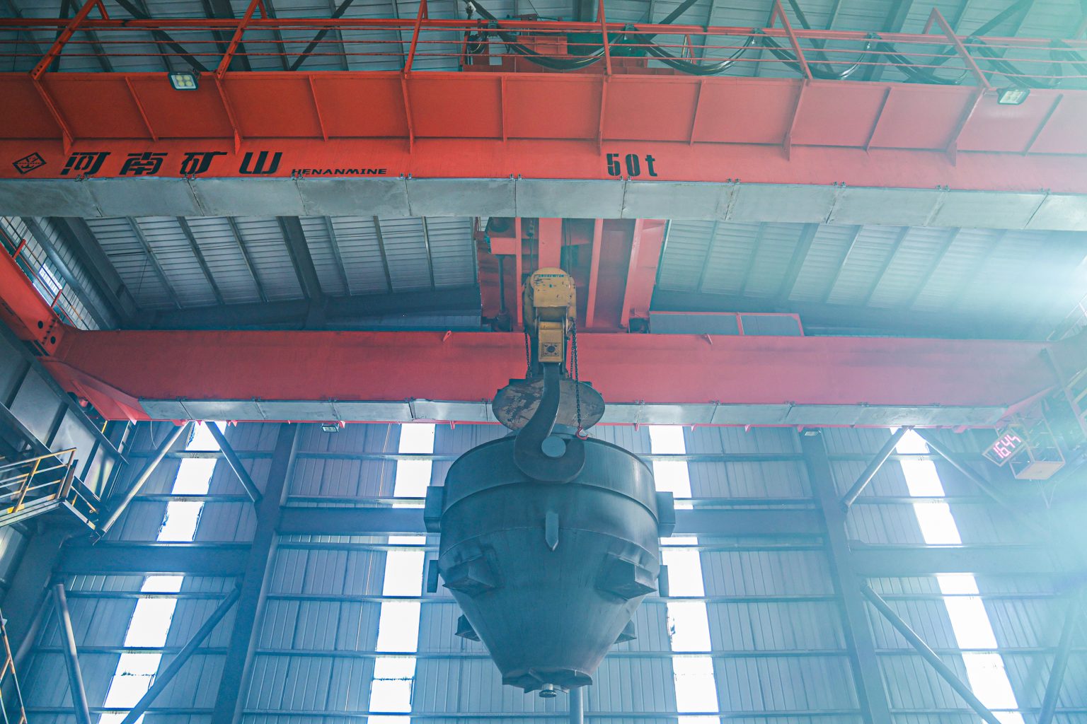
    foundry overhead crane transporting a molten metal ladle
    Foundry crane configured around ladle geometry, pickup points, furnace clearance, transfer route and controlled set-down positions.

    1. Secure Ladle Engagement

    The gantry-type plate hook or ladle beam engages both trunnions within the defined clearance envelope. Attachment geometry must control seating, disengagement risk, side loading and inspection access.

    2. Stable Vertical Lift

    The main hoist raises the complete suspended load with controlled acceleration. Reeving symmetry, drum arrangement, brake control and low-speed capability influence ladle stability.

    3. Controlled Cross and Long Travel

    Trolley and bridge drives transport the ladle through the approved route. Variable-frequency control, defined approach speeds and interlocks can reduce abrupt motion near furnaces, ladle cars and pouring stations.

    4. Pouring or Safe Placement

    Where the process requires crane-assisted pouring, the auxiliary hook and ladle arrangement are evaluated as one system. Normal placement and emergency set-down locations are defined before controls and operating procedures are finalized.

    Foundry Crane Structure and Hoisting Safety

    Engineered Primary Load Path

    Girders, trolley frame, drums, ropes, sheaves, equalizing elements, hooks and ladle attachment are evaluated for rated, dynamic, off-centre and process-specific load cases.

    Hoisting Redundancy

    Dual drive trains, multiple brakes, drum brakes, balancing devices or emergency operating provisions can be specified where required by capacity, risk assessment and governing rules.

    Braking and Limits

    Service and emergency braking functions, upper limits, overload limiting, overspeed response and travel limits are defined by function, setpoint, independence and test method.

    Thermal Protection

    Heat shields, protected cables, metallurgical-duty motors, ventilated cabinets, insulated cabins and temperature monitoring can protect critical equipment from radiant heat and dust.

    YZS four girder foundry crane with dual trolley arrangement
    Four-girder, four- or six-rail, dual-trolley arrangement for ultra-heavy ladle handling and coordinated main and auxiliary functions.

    No single component list establishes molten-metal lifting safety. The technical agreement must define the complete safety architecture, credible failure conditions, functional response, verification procedure, destination regulations and responsibilities for crane, runway, power supply and operating procedure.

    Foundry Crane Specifications

    The product family covers several structural arrangements. Listed values are initial model ranges; each commercial proposal requires confirmation against the ladle, process cycle, building and selected standard.

    Product Family Capacity Span Lifting Height Working Class Arrangement
    YZD Metallurgical Crane 5–200 t 10–35 m 8–30 m A6–A8 Project-specific metallurgical configuration
    YZ Double-Girder Foundry Crane 50–150 t 10–35 m 6–25 m A7–A8 Double girder, single trolley
    YZS Four-Girder Casting Crane 200/50–500/200 t 10–40 m 6–30 m A7–A8 Four girders, four or six rails, dual trolley
    YZ double girder foundry crane for ladle handling
    YZ double-girder foundry crane for medium- and heavy-capacity ladle transfer. Final capacity, span, lift, duty and safety architecture are project-specific.

    Control, Monitoring and Operator Protection

    Operator Cabin

    An enclosed, thermally protected cabin provides a stable operating position for long travel and continuous foundry duty. Sightlines, glazing, access, ventilation and emergency egress require project review.

    Remote or Automatic Control

    Radio remote, remote station or automatic operation can be evaluated when visibility, exclusion zones, communications, risk assessment and process interlocks support the selected method.

    Drive and Motion Control

    Variable-frequency drives, low-speed approach, controlled acceleration and coordinated bridge drives support stable transfer. Required speeds follow cycle-time and ladle-stability calculations.

    Condition and Safety Monitoring

    Load, brake state, motor temperature, cabinet temperature, limits, travel position and selected drivetrain conditions can be monitored, alarmed and recorded within the agreed control scope.

    Representative Foundry Crane Projects

    A relevant project record identifies the handled load, structural arrangement, operating environment and process function. The following installations demonstrate heavy and ultra-heavy molten-metal crane engineering.

    360 ton four girder foundry crane project
    360 t foundry crane with a four-girder, four-rail, dual-trolley structure for a heavy casting workshop.

    PROJECT CASE 01 · ULTRA-HEAVY FOUNDRY

    360 t Four-Girder Foundry Crane

    CAPACITY

    360 t

    STRUCTURE

    Four Girder

    TROLLEYS

    Dual Trolley

    Henan Mine Crane developed the 360 t system for a heavy casting workshop handling molten metal and large moulds. The four-girder, four-rail arrangement distributes the ultra-heavy trolley and operational loads across the structure.

    The project demonstrates the additional engineering required for very high capacity: dual-trolley operation, high-temperature protection, redundant hoisting functions, wheel-load coordination and a defined interface with the plant runway.

    Review the 360 t Foundry Crane Project

    four girder casting bridge crane in a metallurgical plant
    Four-girder casting bridge crane developed for continuous foundry and metal-smelting operations.

    PROJECT CASE 02 · CONTINUOUS CASTING DUTY

    Four-Girder Casting Crane for Foundry Production

    STRUCTURE

    Four Girder

    RAILS

    Four Rail

    SERVICE

    Molten Metal

    This configuration addresses ladle lifting, molten-metal transfer, pouring and selected general handling within steel, foundry and non-ferrous smelting plants. Independent main and auxiliary trolley functions support separate heavy-lift and process-assistance tasks.

    The structural and mechanical design is developed around repeated heavy duty, torsional stability, heat shielding, operator protection and maintainable access to critical hoisting and travel equipment.

    Review the Four-Girder Casting Crane Project

    Engineering, Manufacturing and Project Documentation

    A foundry crane purchase specification should establish the design basis, safety functions, manufacturing inspections, factory tests and handover records before fabrication. Henan Mine Crane aligns the document schedule with the agreed product scope and destination requirements.

    Engineering Package

    • Design criteria and duty classification basis
    • General arrangement, hook coverage and clearance drawings
    • Wheel loads and runway reaction schedule
    • Safety-function and control-system narrative

    Manufacturing Controls

    • Material identification and agreed certificate review
    • Welding procedure, inspection and dimensional verification
    • Drum, sheave, rope, brake and wheel alignment checks
    • Heat shielding, cab and electrical enclosure inspection

    Testing and Handover

    • Factory mechanism, brake, limit and interlock tests
    • Inspection records and component certificates
    • Site commissioning and specified load testing
    • Operation, maintenance and spare-parts documentation

    Applicable standards, third-party inspection, witness points, functional tests, certificate formats and document language must be named in the inquiry and purchase agreement. Compliance is confirmed for the selected crane and project scope, not inferred from another model or installation.

    Delivery, Installation, Commissioning and Maintenance

    Shipment and Site Readiness

    Transport segmentation, packing, unloading route, erection equipment, runway completion, power availability and shutdown permits are coordinated before dispatch.

    Erection and Alignment

    Installation covers bridge and trolley assembly, rail and wheel interface checks, attachment setup, electrification, cabin systems and verification of process clearances.

    Commissioning and Acceptance

    Commissioning verifies motions, brakes, limits, overload functions, emergency responses, communications, alarms, interlocks and specified no-load and load tests.

    Lifecycle Maintenance

    Inspection plans address ropes, sheaves, drums, hooks, ladle attachments, brakes, wheels, rails, heat shields, cabins, electrical equipment and safety functions based on duty and condition.

    Foundry Crane Price and Complete Cost Scope

    For early capital planning, current international listings for new foundry and ladle crane equipment span approximately US$48,000 to more than US$2,000,000 per set. The range covers materially different products—from relatively basic double-girder models to ultra-heavy four-girder, dual-trolley systems—and cannot be treated as a standard selling price.

    Henan Mine Crane quotations are project-specific. Capacity, ladle mass and geometry, span, lifting height, working class, redundant hoisting scope, heat protection, controls, certification, runway work and site services can change the budget substantially. Large 200–500 t systems and complete installed projects may exceed public equipment-only listings.

    Cost Package Typical Inclusions Principal Cost Drivers
    Crane Equipment Bridge, trolley or trolleys, hoisting and travel mechanisms, cabin, controls, electrification and specified safety functions Capacity, span, lift, duty, speed, redundancy, heat exposure and control architecture
    Ladle Attachment and Rigging Gantry-type plate hook, ladle beam, forged hooks, sheaves, rigging interfaces and special monitoring as agreed Ladle geometry, trunnion interface, heat, load case, rotation and inspection requirements
    Runway, Building and Electrical Work Rails, runway beams, columns or reinforcement, conductor system, isolators, feeder and plant interfaces when included Runway length, wheel loads, existing structure, foundations, power supply and local construction rates
    Delivery, Erection and Acceptance Packing, freight, unloading, erection supervision or installation, commissioning, load testing, training and inspection support Destination, shipment size, access, labor, test loads, shutdown schedule and regulatory process

    A valid commercial comparison uses the same complete suspended load, span, lift, duty, redundancy, heat protection, control method, standards, attachment, runway boundary, delivery term, documentation and site-service scope. Equipment-only offers are not directly comparable with installed-system quotations.

    Foundry Crane FAQ

    Is a foundry crane the same as a ladle crane or casting crane?

    The terms commonly overlap when the crane lifts molten-metal ladles. A purchase specification should still identify the exact material, ladle, attachment, transfer route and pouring function because not every metallurgical crane is approved for direct molten-metal handling.

    When is a four-girder foundry crane preferred?

    Four-girder construction is evaluated for ultra-heavy ladles, demanding torsional and wheel-load conditions, separate main and auxiliary trolleys, multi-function operation and high production criticality. Final selection depends on structural calculation and risk assessment.

    How is foundry crane capacity calculated?

    Rated load must account for the molten metal, ladle shell and refractory lining, ladle beam or gantry hook, rigging and allowances required by the governing design basis. Liquid-metal mass alone is not the crane capacity.

    Does every foundry crane require two motors and two reducers?

    Redundancy depends on rated load, operating risk, destination rules and selected standard. Dual drive trains, multiple brakes or an emergency brake can be required for some projects, while another approved architecture may apply to a different capacity and duty.

    Which working class is used for foundry cranes?

    Henan Mine Crane foundry product families are listed from A6 to A8, with direct production ladle cranes commonly in the A7–A8 range. The final class follows the selected classification system, operating hours, starts, load spectrum and process criticality.

    How is the crane protected from foundry heat?

    Protection can include shields below girders and trolley equipment, heat-resistant cables and motors, cooled or ventilated cabinets, protected braking equipment, thermal monitoring and an insulated operator cabin. The package follows measured ambient and radiant exposure.

    Can a foundry crane use an existing runway?

    An existing runway can be considered after checking rail condition and alignment, vertical and horizontal reactions, columns, brackets, foundations, crane clearances and the effect of heat. Structural verification is required before crane manufacture.

    Is cabin or remote control more suitable?

    Cabin control is common for intensive ladle transfer because it provides a defined protected station. Radio remote or automatic control can be evaluated when visibility, exclusion zones, communications, emergency response and process risk support the method.

    How much does a foundry crane cost?

    International listings for new foundry and ladle crane equipment currently span approximately US$48,000 to more than US$2,000,000 per set. Final cost depends on capacity, structure, duty, redundancy, attachment, heat protection, runway work, freight, installation and inspection scope.

    What information is required for a foundry crane quotation?

    The RFQ should include metal type and temperature, liquid-metal and complete ladle mass, ladle and trunnion drawing, required attachment, span, lift, runway length, operating cycle, transfer route, power supply, site environment, governing standards and delivery and installation boundary.

    Request a Foundry Crane Quote

    Henan Mine Crane prepares a project-specific foundry crane configuration, safety scope and commercial schedule from the process and site data. The RFQ should include:

    • Molten-metal type and temperature, liquid-metal mass, complete ladle mass and normal fill level.
    • Ladle drawing, trunnion diameter and centres, required ladle beam or gantry hook and pouring method.
    • Runway span, lifting height, runway length, rail elevation, building section and available wheel-load limits.
    • Heat schedule, lifts per hour, load spectrum, travel distances, required speeds and production criticality.
    • Ambient and radiant heat, dust, fumes, splash exposure, cabin position and preferred control method.
    • Power supply, project country, governing standards, inspection plan, delivery term and installation boundary.
    Henan Mine CraneDiscuss your requirements ↗
  • Factory and Workshop Cranes

    Factory and Workshop Cranes

    Factory and Workshop Cranes

    Henan Mine Crane · Industrial Material Handling Systems

    Factory and Workshop Cranes

    Factory and workshop cranes provide controlled lifting, cross-bay transfer and workstation coverage for production, assembly, maintenance, warehousing and internal logistics. Henan Mine Crane configures overhead bridge cranes, underhung systems, double-trolley cranes and gantry solutions around the load, process route, building structure and operating duty.

    Each project is engineered from verified plant data. Rated capacity alone is not a complete specification: span, lifting height, headroom, runway reactions, duty class, motion speeds, controls, environment, electrical supply and installation scope determine the correct crane system and commercial offer.

    factory overhead crane installed above an industrial production workshop
    An overhead crane keeps the production floor clear while providing hook coverage across the required workshop bay.

    SYSTEM FAMILY

    Overhead, Underhung or Gantry

    RATED CAPACITY

    Defined by Maximum Lifted Load

    LAYOUT BASIS

    Bay, Runway and Process Route

    PRICE BASIS

    Project-Specific Quotation

    What Are Factory and Workshop Cranes?

    Factory cranes and workshop cranes are industrial lifting systems selected to move machinery, components, tooling, fabricated structures, raw materials and maintenance loads within a defined production area. The search term describes an application family rather than one fixed crane model.

    A top-running overhead bridge crane is commonly selected when full-bay coverage, unobstructed floor space and regular production lifting are required. An underhung crane can suit light or moderate loads where a suitable roof structure exists. A freestanding runway separates crane loads from the building. Gantry and semi-gantry cranes are alternatives when legs and floor-level travel rails are acceptable.

    Production Handling

    Movement of workpieces between machining, welding, assembly, inspection and dispatch stations.

    Equipment Assembly

    Controlled positioning of frames, modules, molds, fixtures, engines and large machine components.

    Plant Maintenance

    Planned removal and replacement of motors, pumps, dies, rollers and production-line equipment.

    Internal Logistics

    Transfer between receiving, buffer storage, process cells and outbound staging without occupying floor aisles.

    Selection Considerations

    01 / LOAD

    Maximum Load and Attachment

    Record the heaviest regular and occasional loads, dimensions, center of gravity, pick points and the mass of hooks, beams, magnets, grabs or fixtures.

    02 / PROCESS

    Travel Path and Coverage

    Map loading points, machines, assembly positions, storage areas, obstructions, restricted zones and required hook approaches throughout the bay.

    03 / DUTY

    Cycles and Load Spectrum

    Define lifts per hour, operating hours, typical load distribution, travel distances, starts, inching demand and expected service life.

    04 / GEOMETRY

    Span, Lift and Headroom

    Confirm rail span, highest load position, floor-to-rail elevation, roof clearance, end approaches and hook side-approach requirements.

    05 / STRUCTURE

    Building and Runway Capacity

    Verify column spacing, brackets, roof steel, runway beams, rail condition, wheel-load limits, deflection criteria and foundation capacity.

    06 / ENVIRONMENT

    Indoor Operating Conditions

    State temperature, humidity, dust, fumes, corrosive agents, hazardous-area classification, washdown exposure and any hot-material duty.

    07 / MOTION

    Speed, Control and Accuracy

    Specify required lifting and travel speeds, positioning tolerance, anti-sway needs, radio control, cabin operation and automation interfaces.

    08 / SCOPE

    Standards and Project Boundary

    Define applicable standards, runway responsibility, power supply, freight terms, erection, commissioning, load testing, training, spares and documentation.

    A dependable quotation requires a plant layout or bay dimensions, maximum load data, required lifting height, operating frequency, runway information, local power supply, installation location and required delivery scope.

    Factory and Workshop Crane System Comparison

    The correct configuration is determined by the lifting task and supporting structure. The following systems address different operating and building conditions.

    Crane System Suitable Operating Profile Structural Requirement Principal Selection Boundary
    Single-Girder Bridge Crane General production, maintenance and material transfer with moderate capacity and duty Top-running runway supported by building brackets or independent columns Economical full-bay coverage when load, span and service intensity remain within the selected design
    Low-Headroom Electric Overhead Crane New or existing workshops requiring efficient vertical space and controlled motion Runway geometry coordinated with compact hoist and end-carriage arrangement Selected where hook height, smooth control and reduced wheel loads provide project value
    Double-Girder Bridge Crane Heavier loads, wider spans, higher duty, maintenance platforms or specialized trolleys Top-running runway designed for the calculated vertical, horizontal and dynamic reactions Preferred when performance and serviceability justify greater equipment and runway requirements
    Underhung Workshop Crane Light or moderate handling where floor columns must be minimized Runway suspended from verified roof framing or dedicated overhead steelwork Building support capacity and permissible roof deflection must be confirmed before selection
    Double-Trolley Overhead Crane Long, flexible or off-center loads requiring two lifting points and coordinated movement Bridge and runway sized for trolley positions, combined loads and governing wheel reactions Load-sharing logic, lifting-beam design and allowable skew must form part of the operating procedure
    Gantry or Semi-Gantry Crane Indoor bays without suitable elevated runway support or with a partial building runway Crane legs transfer loads to floor rails, foundations or a combined floor-and-building arrangement Legs and rails occupy floor zones and must be separated from personnel, vehicles and production equipment

    Crane Systems for Factory and Workshop Workflows

    single girder workshop crane serving a factory production bay
    A single-girder overhead crane can provide economical three-axis handling for routine workshop production and maintenance.

    Machining and Fabrication

    Cranes transfer plate, structural sections, fixtures and workpieces between cutting, machining, welding and inspection areas. Hook approaches and travel routes are coordinated with machine envelopes and safe access zones.

    Assembly and Positioning

    Variable-speed drives, low-speed hoisting and suitable below-the-hook devices support controlled alignment of frames, modules, dies and mechanical assemblies.

    Maintenance and Tool Change

    Maintenance coverage can include production machinery, utilities and service pits. Occasional heavy lifts still govern rated capacity, even when daily loads are lighter.

    Receiving and Dispatch

    End approaches, building doors and loading areas are considered so material can move efficiently between transport, staging and production without unsafe cross-traffic.

    Workshop Layout and Supporting Structure

    Crane performance depends on the interaction between bridge geometry, runway alignment, building stiffness and operating clearances. Layout coordination should begin before the crane specification is frozen.

    Existing Building Assessment

    Available drawings, actual dimensions, rail survey data and structural calculations establish whether existing columns, brackets, roof members and foundations can accept crane reactions.

    Independent Runway Option

    A freestanding steel runway can isolate crane reactions from the building. Column positions, foundation loads, aisle clearance and installation access require coordination with plant equipment.

    New Factory Coordination

    Early crane data allows the building designer to reserve rail elevation, column brackets, roof clearance, maintenance access, conductor routing and erection openings.

    double girder bridge crane integrated with an industrial workshop runway
    Runway reactions, hook approaches, service clearances and building interfaces are coordinated as one crane project.

    Configurable Factory Crane Specification

    The final data sheet is issued for the selected crane and project conditions. The schedule below identifies the principal procurement inputs and engineering decisions.

    Specification Item Project Definition Engineering Significance
    Rated capacity Maximum lifted load plus applicable attachment allowance Governs hoist, bridge, trolley, brakes and structural reactions
    Span and runway length Verified rail center distance and required longitudinal coverage Determines girder design, end carriages, conductor length and travel limits
    Lifting height and headroom Lowest pick point, highest load position, rail elevation and roof clearance Defines rope length, hook path and low-headroom requirement
    Duty classification Service based on cycles, load spectrum and operating time Aligns mechanism and structure life with actual production demand
    Hoisting and travel speeds Main speeds, low-speed range and acceleration requirements Balances cycle time, load control, motor power and wheel behavior
    Control method Pendant, radio remote, cabin, fixed station or automated interface Matches operator position, visibility, process risk and control architecture
    Electrical supply Site voltage, frequency, phases, earthing and control voltage Establishes motors, panels, protection and conductor arrangement
    Environment and protection Temperature, dust, humidity, corrosion, hazardous zones and indoor exposure Sets enclosure, insulation, coating, component and special-protection requirements

    Hoisting, Controls and Production Integration

    intelligent electric hoist bridge crane for factory production handling
    Drive control, load monitoring and plant-system interfaces can be selected for the defined production and maintenance requirements.

    Wire-Rope Hoist or Open-Winch Trolley

    Compact electric wire-rope hoists suit many general workshop duties. Open-winch trolleys support heavier capacity, higher duty, greater lifting height, redundant arrangements and specialized process requirements.

    Variable-Frequency Motion

    Variable-frequency drives can provide controlled acceleration and deceleration, low-speed positioning and reduced load swing. Speed ranges are selected from process cycle and control requirements.

    Operator Interface

    Pendant control supports close-range handling; radio remote control improves mobility and viewing position; a cabin can suit intensive or elevated operations. Control mode follows the risk assessment and operating procedure.

    Monitoring and Automation

    Available functions can include load display, operating-hour records, fault diagnostics, restricted zones, position feedback, anti-sway logic and data exchange with plant control or manufacturing systems.

    Safety and Reliability Configuration

    Protective functions are selected from the crane type, operating risk, applicable standard and plant rules. Safety devices support a controlled lifting system but do not replace trained operation, planned inspection or a site-specific safe system of work.

    Lifting Protection

    Upper and lower travel limits, overload protection, brake monitoring where specified and rope-guidance provisions.

    Travel Protection

    End limits, buffers, rail sweeps, audible or visual warnings and anti-collision functions for multiple cranes.

    Electrical Protection

    Main isolation, emergency stop, phase and circuit protection, earthing and enclosure ratings matched to the site.

    Maintenance Access

    Service platforms, guarded access, lighting, inspection points and maintainable component arrangement where required.

    Factory Crane Project Applications

    Completed manufacturing applications demonstrate why production route, building interfaces and operational data must be considered together. Project scope and specifications remain specific to each facility.

    large span suspension crane installed in an industrial workshop
    Large workshop layouts can require multi-support or suspension arrangements developed around roof structure, runway geometry and production coverage.

    Smart Factory Crane Application

    A customized lifting package supports non-excavation equipment manufacturing, with the crane arrangement developed for large workpieces, high-bay workshop conditions, controlled motion and intelligent factory integration.

    Industrial Manufacturing Crane Application

    Batch crane supply for construction-machinery manufacturing addresses production-line handling, operational reliability, monitoring functions and interfaces with digital plant-management systems.

    Manufacturing and Factory Inspection

    Factory-production scenes provide additional visibility into structural fabrication, component assembly and crane manufacturing capability before technical and commercial evaluation.

    Engineering, Manufacturing and Documentation

    ENGINEERING

    Design Input Review

    Load cases, classification, crane geometry, wheel reactions, power, controls and building interfaces are reviewed before detailed design.

    FABRICATION

    Controlled Manufacturing

    Material traceability, cutting, welding, dimensional inspection, machining, assembly and coating follow the approved manufacturing plan.

    TESTING

    Inspection and Functional Checks

    Dimensional checks, electrical inspection, mechanism operation, limit functions and specified factory tests are recorded before dispatch.

    DOCUMENTATION

    Project Document Package

    Approved drawings, data sheets, component information, manuals, certificates and test records are supplied as defined by the contract.

    Typical Technical Submittals

    • General arrangement drawing with span, approaches, hook path, rail level and principal dimensions
    • Wheel loads, power demand, conductor data and equipment interface schedule
    • Mechanism, motor, brake, rope, hook, wheel and electrical component data
    • Electrical schematics, control description and terminal or communication interfaces
    • Operation, inspection, maintenance, lubrication and recommended spare-parts information

    Installation, Commissioning and Maintenance

    Pre-Installation Verification

    Runway span, rail alignment, elevation, clearances, power availability, erection access and lifting resources are confirmed before assembly begins.

    Erection and Commissioning

    The agreed scope can cover assembly guidance, mechanical alignment, electrical connection, functional checks, commissioning, load testing and operator or maintenance training.

    Planned Maintenance

    Inspection intervals reflect operating duty, local regulations and component instructions. Brakes, ropes, hooks, wheels, rails, fasteners, lubrication, electrical protection and limit devices require documented attention.

    Lifecycle Support

    Recommended commissioning spares and operating spares can be quoted with the crane. Accurate equipment identification supports future parts supply and technical service.

    gantry crane operating inside a factory workshop
    Indoor gantry arrangements require clear travel routes, suitable floor support and controlled separation from plant traffic.

    Factory and Workshop Crane Price

    Factory crane price varies substantially because public figures often cover different supply boundaries. Equipment-only quotations may exclude runway steel, columns, electrification, freight, duties, erection, commissioning and testing. A valid commercial comparison requires the same capacity, span, duty, controls, components, standards and delivery scope.

    Public 2026 market listings provide only broad budget context. Basic China-export single-girder crane equipment is commonly advertised from approximately US$3,000, with many 5–10 ton equipment packages appearing around US$5,000–15,000. Public 10–20 ton double-girder examples frequently appear around US$25,000–60,000, while large or heavy-duty systems can exceed US$130,000. North American freestanding workstation systems can be substantially higher: published 0.5 ton system-and-support packages appear around US$12,000–27,000, and one published 3 ton two-cell system is approximately US$82,660. These figures are not Henan Mine Crane quotations and should not be used without scope normalization.

    Crane Equipment

    Bridge or gantry structure, hoist or trolley, end carriages, drives, electrical equipment, controls and selected safety functions.

    Supporting Infrastructure

    Runway beams, columns, rails, foundations, conductor system, access platforms, building modifications and plant power interfaces.

    Delivery and Site Work

    Packing, inland transport, ocean freight, insurance, import charges, erection resources, commissioning, testing and training.

    Information Required for an Accurate Price

    Maximum load and attachment · span · lifting height · runway length · operating cycles · duty classification · required speeds · control method · building or runway data · environment · voltage and frequency · installation country · delivery terms · erection, testing and documentation scope.

    Factory and Workshop Crane FAQ

    Which crane type is most suitable for a general workshop?

    A single-girder top-running overhead crane is often suitable for general light and medium production duties. Capacity, span, duty and building support must still be verified. Double-girder, underhung or gantry designs may be more appropriate under different conditions.

    How is factory crane capacity selected?

    Rated capacity must cover the maximum lifted load and any lifting attachment included in the suspended mass. Load geometry, center of gravity, dynamic effects and occasional maintenance lifts also require consideration.

    Can an overhead crane be installed in an existing factory?

    Installation is possible when dimensions, clearances, runway condition and structural capacity are verified. If the building cannot support the calculated reactions, an independent runway or gantry arrangement can be evaluated.

    What information is needed to confirm crane span?

    Crane span is normally based on the verified center-to-center distance between runway rails. Building width alone is insufficient. Rail geometry, end clearance and hook approaches are also required.

    When is a double-girder workshop crane required?

    Double-girder construction is commonly evaluated for heavier loads, wider spans, higher operating duty, greater lifting height, maintenance platforms or specialized trolley and attachment arrangements.

    What is the difference between an underhung crane and a top-running crane?

    An underhung crane travels on the lower flange of a suspended runway, while a top-running crane travels on rails above the runway beams. Capacity, span, approach, building reactions and headroom differ between the systems.

    Can one crane serve several production machines?

    One overhead crane can serve multiple stations within its hook coverage when travel routes, machine clearances, cycle demand and scheduling are compatible. Overlapping cranes or local lifting devices may be required for simultaneous operations.

    Does a crane quotation include the runway and installation?

    Not automatically. Crane equipment, runway steel, rails, electrification, freight, erection, commissioning and load testing can be separate scope items. The commercial schedule should state every inclusion, exclusion and interface.

    Can workshop cranes use radio remote control?

    Radio remote control can be specified for many workshop cranes. The final control concept considers operator visibility, emergency controls, interference management, backup operation and site safety rules.

    How can comparable factory crane quotations be evaluated?

    Compare rated load, span, duty, speeds, motor and brake data, structural weights, wheel loads, electrical brands, safety functions, runway scope, documentation, testing, freight terms, installation and lifecycle parts support.

    Project Engineering and Commercial Proposal

    Request a Factory and Workshop Crane Quote

    Submit the maximum load, workshop dimensions, span, lifting height, runway information, operating frequency, power supply, installation location and required project scope. Henan Mine Crane will prepare a configuration and quotation based on the verified application data.

    Henan Mine CraneDiscuss your requirements ↗
  • EOT Crane

    EOT Crane

    EOT Crane

    Henan Mine Crane · Electric Overhead Travelling Cranes

    EOT Crane

    An EOT crane—short for Electric Overhead Travelling crane—lifts and transfers materials across a working bay using an electrically powered hoist, trolley and travelling bridge. Elevated runways support the bridge as it moves between loading, production and storage positions.

    Henan Mine Crane manufactures single-girder, double-girder and underhung EOT cranes for workshops, warehouses, equipment assembly and maintenance. Match the crane to your load, building clearances and operating cycle, with the selected configuration and supply scope identified in the quotation.

    Double-girder EOT crane with electric hoist trolley from Henan Mine Crane
    Double-girder electric-hoist EOT crane. Capacity, hook levels and runway interfaces are selected for the installation.

    FULL NAME

    Electric Overhead Travelling

    POWERED MOTIONS

    Hoist, Cross Travel and Long Travel

    BRIDGE OPTIONS

    Single or Double Girder

    SELECTION INPUTS

    Capacity, Span, Lift and Duty

    How Does an EOT Crane Work?

    EOT crane, electric overhead crane and electric bridge crane commonly describe the same industrial arrangement. Its three motions position the hook within the working envelope:

    Hoisting: Raise and Lower

    The hoist motor, transmission, rope drum and hook system lift the suspended load. Required hook travel and handling accuracy guide the hoist arrangement and speed selection.

    Cross Travel: Across the Bay

    The trolley or travelling hoist moves along the bridge. This motion reaches pickup and placement points across the span, within the hook’s side approaches.

    Long Travel: Along the Bay

    Powered end carriages move the bridge along its runways. Runway length, end stops and crane dimensions determine the usable longitudinal coverage.

    Workshop EOT cranes can transfer fabrications between machines, position assemblies or remove equipment for repair. Warehouse applications require access around stored goods and vehicle loading areas. Mark these handling routes on the building plan before selecting the bridge arrangement.

    EOT Crane Technical Specifications

    These selected product references provide a starting point for an EOT crane enquiry. Each row corresponds to the linked model or model family; the single-girder entries are specific examples from its capacity tables.

    Product Reference Rated Capacity Span Lifting Height
    Single-Girder EOT: 5 t Reference 5 t 7.5–28.5 m 6, 9, 12, 18, 24 or 30 m
    Single-Girder EOT: 10 t Reference 10 t 7.5–28.5 m 6, 9, 12, 18, 24 or 30 m
    LH Double-Girder Electric-Hoist EOT 3–32 t 7.5–31.5 m 6–30 m
    Single-Girder Suspended EOT 1–10 t 7.5–28.5 m 6–20 m

    The unit t denotes a metric tonne. The final combination of capacity, span, lifting height and operating duty requires project confirmation. Maximum values in different columns are not automatically available together.

    Complete the Technical Specification

    • Highest and lowest hook positions, runway length, side approaches and end approaches.
    • Typical and maximum loads, lifting attachment weight, operating shifts and handling cycles.
    • Hoist, cross-travel and long-travel speeds, including any positioning requirement.
    • Site voltage, frequency, phases, power connection and pendant, radio or cabin control.
    • Crane and mechanism duty, design standard, environment, wheel loads and maintenance access.

    Selection Considerations

    01 / LOAD

    Define the Lift

    Provide the maximum load, typical load, dimensions and lifting points. Include the weight and arrangement of slings, lifting beams or other attachments when defining the required lifting capacity.

    02 / SPACE

    Check the Building

    Supply a plan and cross-section showing runway spacing, runway elevation, roof members, columns and services. For existing facilities, identify obstructions and the condition of the supporting structure.

    03 / DUTY

    Describe the Work Cycle

    List lifts per hour, travel distances and operating shifts. An assembly crane making occasional heavy lifts and a production crane handling loads repeatedly can require different mechanisms despite the same rated capacity.

    04 / CONDITIONS

    Define the Environment

    State indoor or outdoor operation, temperature, dust, humidity and corrosion exposure. Hazardous atmospheres, hot loads and process attachments need their own equipment and protection requirements.

    EOT Crane Compared with Other Industrial Crane Configurations

    Single girder and double girder describe the bridge structure. Top running and underhung describe its connection to the runways. A hoist hanging below a beam does not make the whole crane an underhung design.

    Configuration Arrangement Selection Implication
    Single-Girder EOT Crane One bridge girder, commonly with a travelling electric hoist beneath it. Compare the installed cost, hook height, side approaches and specified duty for workshop or maintenance handling.
    Double-Girder EOT Crane Two bridge girders supporting the selected hoist trolley. Can accommodate different trolley layouts and hook elevations. Include the crane envelope, runway loading and access requirements in the comparison.
    Single-Girder Underhung EOT Bridge end carriages travel on the lower flanges of suitable runway beams. Evaluate runway flange loading, suspension connections and the structure supporting those beams.
    Multi-Support Underhung EOT A suspended bridge arranged across several runway supports. Suited to an engineered multi-rail layout. Support alignment and load distribution require coordinated design.
    Gantry Crane Travelling legs support the bridge, usually above ground-level runways. Consider where elevated crane runways are unsuitable. Allow for legs, travel lanes, foundations and load clearance.

    Working Duty, Load Spectrum and Production Cycles

    Rated capacity describes a lifting limit; duty selection also considers how the crane will be used over time. A larger capacity label alone does not establish suitability for continuous production.

    Load Spectrum

    Record how often loads are light, intermediate or close to rated capacity. Repeated near-capacity lifts create a different service requirement from occasional maximum lifts.

    Mechanism Operating Time

    Separate time spent hoisting, cross travelling and long travelling from the shift duration. Include repeated positioning movements, starts and any simultaneous motion required by the process.

    Classification and Design Basis

    Identify the applicable standard and the proposed duty for the crane and its mechanisms. Codes from different classification systems need an engineering assessment before they can be treated as equivalent.

    For frequent handling or controlled placement, compare the frequency-conversion electric-hoist overhead crane configuration. Agree the load cycle and required positioning performance before selecting motors, drives and brakes.

    Runway, Headroom and Building Integration

    Span and Hook Coverage

    Crane span follows the runway centreline spacing. The hook cannot normally reach those centrelines because the trolley and bridge have approach limits. Check every machine, loading point and storage position on the plan.

    Headroom and Lifting Height

    Show the highest required hook level relative to the floor and runway. Load depth, lifting gear, crane height, roof clearance and maintenance space all affect the usable lift.

    Runway Loads and Supports

    Provide the proposed wheel loads, wheel spacing and applicable horizontal reactions for structural review. Existing runway beams, rails, connections and supporting columns must suit the selected crane.

    Single-girder EOT crane with a travelling electric hoist below the bridge beam
    Single-girder arrangement with a travelling electric hoist beneath the main beam.
    Multi-support double-girder underhung EOT crane suspended from several runway beams
    Multi-support underhung configuration. The runway beams, connections and supporting structure form part of the installation design.

    For a replacement EOT crane, survey the actual runway and building interfaces. Two cranes with the same lifting capacity can have different wheel loads, wheelbases, hook approaches and power requirements.

    Electrical Supply, Speeds and Operator Controls

    The electrical proposal should identify what is included for each motion. Variable-frequency drives can control acceleration and speed; anti-sway, automatic positioning and production-line interfaces are separate functions with their own requirements.

    System Configuration Requirement
    Hoist Speed Select transfer and positioning speeds around the load and lifting task. Dual-speed or variable-frequency operation is specified for the selected hoist.
    Cross Travel and Long Travel Define these motions separately. Acceleration, deceleration, travel distance and load settling affect the handling cycle as well as maximum speed.
    Electrical Supply State site voltage, frequency, phases and earthing arrangement. Motors, brakes, transformers, controls and incoming protection must be coordinated with that supply.
    Pendant, Radio or Cabin Select around visibility and operator movement. With more than one control station, define control priority, changeover and the response to signal loss.
    Power Distribution Distinguish the runway power feed from power to the moving trolley. Conductor systems, festoons or cable-management arrangements are selected for their respective routes.

    Safety, Special Loads and Process Requirements

    Match the protection schedule to the crane arrangement, operating environment and consequences of a fault. The quotation should distinguish required protections from additional process functions.

    • Load and travel protection: identify overload protection, hoist limits, travel limits, braking, emergency stops and electrical protections, with their intended responses.
    • Shared runways: assess crane separation, collision prevention and access during maintenance where multiple cranes operate in the same bay.
    • Double-trolley EOT cranes: specify individual ratings, permitted shared loads, hook spacing and coordinated controls. Adding two hoist ratings does not establish an unrestricted combined lifting capacity.
    • Grab overhead cranes: select the grab and crane together using material density, payload, attachment weight, discharge height and required throughput.
    • Explosion-proof EOT cranes and metallurgical overhead cranes: define the hazardous-area classification or hot-material process before equipment selection. General workshop configurations cannot be assumed suitable for these duties.

    Additional brakes, monitoring, anti-sway and redundancy arrangements depend on the specified risk and operating duty. Their purpose, scope and acceptance method should be recorded in the technical agreement.

    Manufacturing, Inspection and Technical Documentation

    Crane manufacturing workshop with bridge structures and hoisting equipment at Henan Mine Crane
    Henan Mine Crane production workshop, shown on the company’s factory facilities page.

    Henan Mine Crane manufactures overhead lifting equipment for industrial material handling. The company’s factory facilities page shows its manufacturing workshops and crane structures.

    For your EOT crane order, define the documents and inspections needed to connect the agreed specification with the delivered equipment:

    • General arrangement drawing with capacity, span, hook levels, crane dimensions and runway interfaces.
    • Component schedule and electrical diagrams identifying the supplied hoist, drives, controls and protection functions.
    • Agreed material, fabrication and inspection records, including any specified weld examinations.
    • Factory and site acceptance scope, operation and maintenance manuals, and a spare-parts list.

    Agree witness points and acceptance criteria before manufacture. Any conformity documents must correspond to the ordered equipment and destination requirements.

    Installation and Maintenance

    Installation Preparation

    Coordinate crane delivery with runway readiness, electrical availability, unloading access and assembly space. Identify the lifting equipment and site personnel needed for installation.

    Commissioning and Handover

    Agree alignment checks, control verification, protection checks and the applicable load-test scope. Identify responsibility for test loads, witnessing, records and operator familiarisation.

    Maintenance Planning

    Provide safe access and isolation arrangements for the hoist, ropes, brakes, wheels, drives and electrical system. Base inspection and lubrication schedules on the supplied manuals and actual duty.

    For production-critical applications, identify essential spares and component replacement access before the crane enters service. Service arrangements, documentation language and on-site support belong in the agreed supply scope.

    EOT Crane Price and Supply Scope

    An EOT crane price depends on the selected load, span, lift, duty, mechanism arrangement and installation scope. Two quotations for a 10-ton crane can differ because they include different hoists, controls, runway equipment or site services.

    Compare offers against the same specification and ask for the following scope items to be identified:

    • Crane bridge, end carriages, hoist or trolley, controls and included protection functions.
    • Runway beams, rails, support steelwork and electrical power distribution, with supply boundaries stated.
    • Packing, transport, unloading, installation, commissioning and operator familiarisation.
    • Inspection documents, required spares, service arrangements and delivery terms.

    For a new EOT crane for sale, request a project quotation with the model configuration and exclusions clearly listed. Manufacturing and delivery timing should be confirmed against drawing approval, component availability and the destination.

    Request An EOT Crane Quotation

    EOT Crane FAQ

    What is the full form of EOT crane?

    EOT stands for Electric Overhead Travelling. It describes an overhead bridge crane with electrically powered lifting and travelling motions, used to move materials within the available hook coverage.

    Is an EOT crane the same as an overhead crane?

    EOT is a common name for an electrically powered overhead travelling crane. “Overhead crane” is a broader description, so an enquiry should still identify the bridge arrangement, hoist, runway support and required motions.

    Should a 5-ton or 10-ton EOT crane use one girder or two?

    Both capacities can be considered within different arrangements. Compare required hook height, span, duty, runway loading and installed cost. The 5 Ton Overhead Crane page provides another starting point for a metric 5-ton requirement.

    What is the difference between an EOT crane and an electric hoist?

    The hoist is the lifting mechanism. A complete EOT crane also includes the bridge, travel mechanisms, controls and interfaces to the runway and electrical supply. Confirm which equipment is included when comparing prices.

    Can an EOT crane operate continuously?

    Continuous service requires a specification based on the actual load spectrum, operating time and work cycle. Girder count and rated capacity do not establish continuous-duty capability; crane and mechanism selection must cover the intended service.

    Can the crane run on our existing runway?

    Possibly, after surveying the runway and checking its structure, alignment and electrical interfaces against the proposed crane. Provide existing drawings and condition information, then compare wheel loads, wheel spacing, rail compatibility and clearances.

    Does the quotation include installation and runway steelwork?

    These items depend on the agreed scope. Identify crane equipment, rails, beams, columns, power supply, unloading, erection and commissioning separately, including responsibility for site tests and any local installation work.

    Request An EOT Crane Quote

    Send Henan Mine Crane your required capacity, span, lifting height, working cycle and site power supply. Include the installation country, building drawing, load details and required supply scope so the proposal can address the equipment and its installation interfaces.

    Henan Mine CraneDiscuss your requirements ↗
  • EAF Crane for Electric Arc Furnace Steelmaking

    EAF Crane for Electric Arc Furnace Steelmaking

    EAF Crane for Electric Arc Furnace Steelmaking

    Henan Mine Crane · Engineered Crane Systems for EAF Melt Shops

    EAF Crane for Electric Arc Furnace Steelmaking

    Process-engineered overhead cranes for scrap receiving, charge-bucket handling, molten-steel ladle transfer, slag handling and furnace maintenance in electric arc furnace melt shops.

    Henan Mine Crane configures each electric arc furnace crane system around the charge practice, bucket and ladle geometry, furnace layout, production cycle, thermal exposure, operating duty, automation boundary, runway capacity and destination compliance requirements.

    450 ton four girder EAF crane for electric arc furnace steelmaking
    An EAF melt shop normally uses dedicated crane systems for scrap charging, molten-steel transfer and maintenance rather than one universal crane.

    PROCESS DUTIES

    Scrap, Charging, Ladle, Slag & Maintenance

    CRANE SYSTEMS

    Magnet, Grab, Charging, Casting & Service

    OPERATING DUTY

    Process-Specific Heavy Duty, A7–A8 Available

    PRICE BASIS

    Engineered Project Quotation

    What Is an EAF Crane?

    An EAF crane, or electric arc furnace crane, is a process crane serving one or more material-handling stages in an electric arc furnace melt shop. The term does not describe one universal crane model. It can refer to a scrap-yard crane, a charge-bucket crane, a molten-steel ladle crane, a slag-pot crane or a maintenance crane. Each duty has a different suspended load, attachment, thermal zone, operating cycle and consequence of failure.

    The charging sequence typically begins with scrap receiving and preparation. Magnet or grab cranes sort and load scrap into a charging bucket. A dedicated charging crane then lifts the complete bucket, travels to the furnace and positions it for the approved charging sequence. After melting and refining, a casting or ladle crane transfers the full steel ladle from the furnace tapping area to secondary metallurgy or continuous casting. Service cranes handle furnace roof sections, electrodes, water-cooled panels, refractory equipment and maintenance components only within their engineered duty.

    A procurement specification should define the complete process route before equipment selection. Combining scrap charging, ladle transfer and maintenance in one crane can create incompatible attachments, cycle conflicts and availability risks. Henan Mine Crane evaluates the melt shop as a handling system, assigns each task to the appropriate crane and develops the required capacity, structure, controls and safety functions.

    EAF Crane Types for Electric Arc Furnace Melt Shops

    01 · Scrap Yard Magnet or Grab Crane

    Handles incoming scrap, stockpile management, sorting, blending and charge-bucket loading. Electromagnets suit ferrous scrap with an approved magnet-control strategy; orange-peel grabs suit loose or mixed scrap. The crane is selected from scrap density, attachment mass, pile geometry, bucket volume and hourly throughput.

    02 · Scrap Charging Crane

    Lifts the filled charge bucket from the preparation area and transfers it to the EAF charging position. Capacity includes the bucket, scrap charge, lifting beam or chains and all below-hook components. Furnace roof, electrode mast, fume duct, platform and building clearances govern the approach envelope.

    03 · Ladle Transfer or Casting Crane

    Transfers the full molten-steel ladle from the tapping area to LF, VD, VOD, RH or continuous casting. Double-girder and four-girder configurations use a metallurgical trolley, gantry beam and plate hooks, with main and auxiliary lifting functions selected for transfer and pouring duties.

    04 · Slag Pot Handling Crane

    Moves slag pots between the furnace, cooling area and downstream slag-treatment stations. The crane and attachment are designed around gross pot mass, trunnion geometry, radiant heat, possible deposits, route conditions and the approved tipping or set-down method.

    05 · Furnace Maintenance Crane

    Handles furnace roof sections, electrodes, panels, burner assemblies, refractory equipment and maintenance loads during planned work. It is not a molten-metal or scrap-charging crane unless its structure, mechanisms, controls and acceptance basis explicitly cover those operations.

    06 · Automated EAF Crane System

    Adds position feedback, variable-frequency motion, route zoning, anti-sway functions, load monitoring and plant handshakes. Automatic or assisted sequences are engineered with the furnace supplier and plant integrator so that every permissive, safe state and manual recovery method has a defined owner.

    Compare EAF Crane Configurations

    Crane selection should follow the handled object and process function rather than the shared location inside the EAF building. The same nominal capacity can require a substantially different attachment, duty classification, heat protection, control architecture and acceptance plan.

    Crane Configuration Primary Load Typical Attachment Principal Selection Basis Important Boundary
    Scrap Handling Crane Loose ferrous scrap and prepared charge material Electromagnet, orange-peel grab or combined attachment Scrap density, pile profile, bucket volume, throughput, duty and attachment deadweight Magnet rating and backup strategy must match the load and operating risk
    Scrap Charging Crane Filled EAF charge bucket Charging-bucket lifting beam, hooks or project-specific rigging Maximum gross bucket mass, pickup geometry, furnace approach, charging cycle and clearance study Furnace permission, roof and electrode status and personnel exclusion must be integrated
    Double-Girder Casting Crane Full steel ladle and process tooling Gantry beam with paired plate hooks and auxiliary hook where required Gross suspended load, ladle trunnions, heat, cycle histogram, transfer route and pouring method General double-girder construction alone does not qualify a crane for molten steel
    Four-Girder Casting Crane Ultra-heavy full ladle with main and auxiliary duties Separate main and auxiliary trolleys on four or six rails Main/auxiliary capacities, structural stiffness, redundancy, wheel loads and production availability Higher self-weight, building reactions, erection scope and maintenance demand require early review
    Furnace Service Crane Roof, electrodes, panels, refractory tools and maintenance components Forged hook, beam or dedicated maintenance tool Component mass, headroom, outage sequence, access and maintenance frequency Not permitted for full ladles or charge buckets unless engineered for those loads
    Integrated Automated Package Multiple process loads handled by dedicated cranes Crane-specific attachments with shared supervisory interfaces Production route, station coordinates, traffic management, plant signals and recovery philosophy Functional boundaries between crane PLC, furnace control and plant safety systems must be documented

    System principle: the EAF process should determine the crane package. A scrap charging crane, ladle crane and maintenance crane may share a building, but they should not share an assumed design basis.

    Match the Crane to Each EAF Process Area

    The crane study begins with a coordinated plan and elevation of the scrap yard, charge-bucket preparation area, EAF bay, tapping aisle, secondary metallurgy stations, continuous caster, slag bay and maintenance zones. Pickup and set-down coordinates are checked against the furnace shell, retractable roof, electrode mast, fume-extraction duct, platforms, ladle cars, transfer cars and adjacent crane envelopes.

    The route analysis identifies load elevations, hook approaches, bucket swing, ladle pickup tolerances, obstructions, crane passing rules and emergency set-down locations. A process-ready arrangement also provides inspection access outside uncontrolled heat and traffic zones.

    Separating production and maintenance functions protects throughput. A ladle crane remains available for tapping and caster supply while service equipment supports furnace work. Shared runways require collision avoidance, traffic priority and recovery procedures.

    heavy duty electric arc furnace crane operating in a steel melt shop
    The melt-shop general arrangement controls crane span, lift, approaches, heat zones, station coordinates and traffic rules.
    Process Area Handled Load Crane Function Critical Interfaces Design Emphasis
    Scrap receiving and storage Baled, loose or heavy ferrous scrap Unload, sort, blend, stockpile and reclaim material Truck or rail unloading, stock bays, pile height and pedestrian segregation Attachment selection, duty, throughput, visibility and magnet or grab controls
    Charge-bucket preparation Scrap fractions loaded into the charging bucket Controlled loading and weight distribution Bucket size, loading sequence, weighing system and preparation stations Load distribution, bucket protection, cycle time and traceable charge data
    EAF charging aisle Complete scrap charging bucket Lift, travel, position and support the approved charging sequence Furnace roof, electrodes, fume duct, platform, charging opening and exclusion zone Gross mass, clearance, sway control, slow approach and permissive logic
    Tapping and ladle transfer Full molten-steel ladle Pickup at tapping position and transfer to the next process Ladle car, furnace platform, trunnions, tapping aisle and emergency set-down Metallurgical load path, heat protection, braking, redundancy and availability
    Secondary metallurgy Full ladle at LF, VD, VOD or RH station Place, retrieve and reposition the ladle at treatment stations Electrodes, vacuum equipment, covers, cars and station coordinates Accurate positioning, restricted zones, process signals and anti-sway control
    Continuous casting Full and empty ladles, covers and related tooling Deliver the ladle to the caster and remove it after the sequence Ladle turret, casting platform, tundish route and queue management Repeatability, production priority, traffic control and recovery planning
    Slag and maintenance areas Slag pots, roof sections, panels, electrodes and refractory equipment Slag transfer, shutdown maintenance and component replacement Cooling zones, tipping stations, service platforms and access routes Dedicated attachments, heat exposure, contamination and safe maintenance access

    Technical Selection and Specification Framework

    An EAF crane inquiry should define production duty and acceptance criteria rather than capacity and span alone. These inputs establish the structural, mechanical, electrical and control basis for each crane.

    Specification Item Information to Provide Engineering Decision Why It Changes the Crane
    Maximum gross load Bucket or ladle, contents, lifting beam, hooks, chains, blocks, attachment and every suspended component Rated capacity, load combinations, overload basis and mechanism sizing Controls hoist, ropes, drums, brakes, trolley, girders, wheels and runway reactions
    Load geometry and interface Bucket drawings, ladle trunnions, centers of gravity, pickup points, tilt point and permitted tolerances Beam, hook, plate-hook or rigging geometry and engagement method Determines secure pickup, headroom, load stability and inspection criteria
    Span, lift and approaches Rail span, runway length and elevation, lowest pickup, highest operating position and end approaches Girder form, hoist range, rope capacity, trolley layout and limiting dimensions Confirms access to every station without furnace, duct or building interference
    Cycle and duty spectrum Lifts per heat, heats per day, travel distances, load distribution, shifts, annual hours and availability target Mechanism classification, fatigue design, motor and brake thermal ratings Production cranes are selected by repeated duty and criticality, not nominal load alone
    Motion performance Hoisting and travel speeds, creep speeds, acceleration limits, positioning tolerance and cycle target Drive power, VFD control, feedback, anti-sway functions and brake response Balances production throughput with stable bucket and ladle handling
    Thermal environment Ambient and radiant temperatures by location, exposure duration, hot surfaces, splash zones and ventilation Heat shields, cooling, component placement, insulation, cables and enclosure rating Protects mechanisms and electrical equipment in the verified exposure zone
    Dust, fumes and contamination Scrap dust, conductive dust, furnace fumes, scale, slag, water exposure and housekeeping practice Sealing, pressurization, filters, cabinet location, cable protection and maintenance access Reduces contamination-related faults and supports reliable inspection
    Runway and building Rail section, runway capacity, allowable wheel loads, deflection limits, columns and building reserve Wheel quantity, wheel base, end carriage, rail gauge and structural reactions Can govern crane configuration and building reinforcement cost
    Power and controls Available voltage and frequency, conductor system, PLC platform, network protocol and plant signal list Electrical architecture, control stations, communications, redundancy and interfaces Defines the boundary between crane, furnace, melt-shop and safety systems
    Codes and acceptance Destination, applicable crane and electrical standards, buyer specifications, inspection body and witness plan Compliance matrix, documentation, FAT, proof testing and site acceptance Prevents late redesign and establishes the certification boundary

    Double-Girder Casting Crane Range

    Henan Mine Crane product-family data covers 50–150 t capacity, 10–35 m span, 6–25 m lift and A7–A8 duty, with final values customized to the project.

    Four-Girder Casting Crane Range

    YZS product-family data covers 200/50–500/200 t capacity, 10–40 m span, 6–30 m lift and A7–A8 duty. Final selection follows the EAF project.

    EAF Crane Safety, Redundancy and Heat Protection

    Load Path and Attachment Verification

    The bridge, trolley, hoist, ropes, blocks, beam, hooks, plate hooks, chains and bucket or ladle interface are evaluated as one load path. Engagement geometry, wear limits, inspection access and permissible load orientation are documented for the specific handled object.

    Hoisting Brakes and Protective Functions

    Service and emergency braking functions, operating and final limits, overspeed detection, overload monitoring and safe response to power or drive failure are selected from the governing standard and project risk assessment. The molten-metal crane receives its own critical-function architecture.

    Furnace Charging Permissions

    Charging motion is permitted only within the plant-approved furnace state. Roof and electrode position, charging opening, extraction equipment, crane location, load condition and personnel exclusion can form part of the interlock matrix developed with the furnace supplier and plant integrator.

    Thermal, Dust and Fume Protection

    Heat shields, protected equipment locations, ventilation or cooling, suitable insulation systems, heat-resistant cables, sealed or pressurized cabinets and guarded access are selected from measured environmental data rather than a single assumed furnace temperature.

    Controlled Motion and Collision Management

    Variable-frequency drives, controlled acceleration, creep speeds, position feedback, anti-sway functions, inter-crane spacing, restricted zones and traffic priority support stable movements through the furnace, refining and casting bays.

    Emergency Set-Down and Recovery

    Approved set-down positions, backup functions, manual recovery boundaries, communications, rescue access and incident response are established with plant operations. Recovery planning addresses a loaded charge bucket, a full ladle and a maintenance load as separate scenarios.

    EAF ladle crane transferring molten steel in a melt shop
    Scrap charging and molten-steel transfer require separate load paths, permissions and process sequences.

    Scrap Charging, Ladle Transfer and Process Automation

    A charging cycle starts after the scrap bucket has been prepared and released for transfer. The crane engages the approved pickup points, raises the bucket to travel height and follows the permitted route to the EAF. Final approach uses controlled speed. Charging proceeds only after the furnace system confirms the required roof, electrode, extraction and exclusion-zone conditions.

    Molten-steel transfer follows a separate sequence. The ladle crane engages both trunnions through the gantry beam and plate hooks, lifts from the tapping or ladle-car position and travels to secondary metallurgy or continuous casting. Controlled acceleration, low-speed approach, route permissions and emergency set-down provisions protect the load and process equipment.

    Automation can coordinate positions, speed zones, load identification, anti-sway functions, weighing, collision avoidance, monitoring and plant handshakes. The control narrative defines crane and plant responsibilities, communication-failure behavior and recovery of an interrupted cycle. Higher automation follows validation of routes, sensors and safe states under production conditions.

    Documented Electric Furnace Steelmaking Project

    450 t Four-Girder Casting Crane for an EAF Steelmaking Plant

    Henan Mine Crane engineered a 450 t four-girder, four-rail casting crane for a metallurgical enterprise upgrading its electric furnace steelmaking capacity. It serves ultra-heavy molten-metal transfer and was configured around the plant layout, thermal environment and production duty.

    The project uses heavy-duty lifting machinery with PLC control, industrial Ethernet and safety monitoring for coordinated operation and status supervision. Structural analysis, trolley-frame machining, assembly control and functional testing formed part of project execution.

    This installation represents the ladle-transfer portion of an EAF system, not scrap charging. Charge buckets and full steel ladles require different attachments, routes, hazards and permissions. A new melt shop may therefore combine casting, scrap-yard, charging and maintenance cranes.

    View the 450 t electric furnace crane project →

    450 ton four girder casting crane project for electric arc furnace steelmaking
    450 t four-girder casting crane for ultra-heavy molten-steel handling in an electric furnace steelmaking project.

    Engineering Deliverables and Quality Records

    A procurement-ready proposal defines process assumptions, safety functions, plant interfaces, verification activities and site responsibilities. Contracted records support technical approval, manufacturing traceability and commissioning.

    Design Basis Package

    Approved load schedule, charge bucket and ladle drawings, cycle histogram, general arrangement, clearance study, duty calculations, wheel loads, runway reactions, heat-zone map, station coordinates and compliance matrix.

    Safety and Control Documents

    Functional description, operating modes, brake philosophy, limit and interlock matrix, PLC and network architecture, safe states, charging permissions, emergency set-down logic, alarm list and recovery procedures.

    Manufacturing Quality Records

    Material traceability, welding procedures, welder qualifications, dimensional inspection, NDT, heat treatment or stress-relief records, machining checks, assembly records and coating reports as defined in the contract.

    Factory and Site Acceptance

    No-load and functional tests, brake and limit verification, overload functions, travel motions, communications, fault simulation, proof-load plan, site commissioning, dry process trials and operator-maintenance training.

    Review Henan Mine Crane manufacturing and quality capabilities →

    Installation, Commissioning and Lifecycle Planning

    Runway and Site Readiness

    Survey rail span, elevation, alignment and runway capacity; confirm furnace, duct, platform and station clearances; verify erection access, electrification, control networks, construction sequence and shutdown windows before shipment.

    Installation and Assembly

    Bridge sections, end carriages, trolleys, reeving, beams, attachments, heat shields, conductor systems and control cabinets are assembled under approved lifting, alignment, bolting, welding, torque and electrical procedures.

    Commissioning and Process Trials

    Testing progresses from no-load motions and protective functions to proof loading, brake verification, positioning, interlocks, communications, dry charging-route simulation, ladle-route simulation and controlled production trials.

    Inspection and Maintenance Strategy

    The program covers ropes, drums, sheaves, brakes, hooks, plate hooks, beams, bucket interfaces, structures, wheels, heat shields, cables, sensors, cabinets and controls. Intervals follow actual duty, environment, regulation and manufacturer instructions.

    EAF Crane Price and Supply Scope

    An electric arc furnace crane has no reliable universal list price. A valid budget depends on whether the scope covers scrap handling, charge-bucket transfer, ladle handling, maintenance or an integrated package. Attachments, duty, heat protection, redundancy, automation, runway interface, compliance and site services materially change the price.

    Quotation Level Typical Included Scope Principal Cost Drivers
    Scrap Receiving Crane Bridge or gantry crane, magnet or grab, attachment power and controls, cabin or remote station Scrap throughput, attachment mass, pile area, duty, magnet controls and outdoor protection
    Scrap Charging Crane Heavy-duty crane, bucket lifting interface, controlled drives, heat protection and furnace permissions Gross bucket load, furnace approach, clearance, cycle rate, duty, interlocks and process integration
    Ladle or Casting Crane Double- or four-girder bridge, metallurgical trolley, ladle beam, plate hooks and safety package Gross ladle load, main/auxiliary ratings, redundancy, A7–A8 duty, heat and wheel loads
    Furnace Maintenance Crane Service crane, hook or dedicated tooling, access provisions and maintenance controls Component weights, headroom, thermal zone, outage plan, access and lifting frequency
    Integrated EAF Crane Package Coordinated cranes, engineering, process interfaces, documentation, freight, installation and commissioning Crane count, automation level, destination, trade term, site access, statutory inspection and schedule

    General-crane advertisements commonly exclude process attachments, safety functions, automation, runway work, freight, erection, testing and statutory acceptance. Compare bids against one approved data sheet, functional specification, document list, delivery term and site-service matrix.

    Crane Equipment

    Bridge, trolley, hoists, drives, brakes, ropes, wheels, platforms, access and electrification.

    Process Attachments

    Magnet, grab, charging beam, bucket rigging, gantry beam, plate hooks and slag-pot interface.

    Safety and Automation

    Limits, monitoring, VFDs, PLC, positioning, zoning, plant signals and process sequences.

    Project Services

    Engineering, FAT, packing, freight, erection, commissioning, load tests, trials and training.

    Information Required for an EAF Crane Quote

    A complete inquiry allows each crane, attachment and process interface to be evaluated against one operating basis. Preliminary drawings are suitable when assumptions are identified.

    01 · Melt-Shop Process

    EAF size and heat schedule, scrap practice, tapping route, LF/VD/VOD/RH stations, continuous casting interface, shifts, annual hours and required availability.

    02 · Crane Responsibilities

    Identify separate duties for scrap receiving, bucket loading, furnace charging, ladle transfer, slag pots, furnace maintenance and general service.

    03 · Maximum Gross Loads

    Scrap, bucket or ladle, refractory, slag, beam, plate hooks, chains, blocks, magnet or grab and every suspended component for each permitted load case.

    04 · Load Drawings

    Charge bucket dimensions and pickup points; ladle diameter, height, trunnion size and spacing; center of gravity, tilt point and interface tolerances.

    05 · Building and Runway

    Plans, sections, rail span, runway length and elevation, rail type, allowable wheel loads, headroom, end approaches, building reserve and erection access.

    06 · Stations and Clearances

    Scrap bays, charging position, furnace roof and electrodes, ducts, platforms, ladle cars, refining stations, caster, slag bay and emergency set-down coordinates.

    07 · Duty and Performance

    Lifts per heat, cycle time, travel distances, load spectrum, main and creep speeds, acceleration limits, positioning accuracy and load-sway requirements.

    08 · Environment and Protection

    Ambient and radiant temperatures by zone, dust, fumes, scale, splash, humidity, altitude, outdoor exposure, ventilation and operator environment.

    09 · Controls and Compliance

    Control stations, manual or automated modes, PLC and network preferences, signal list, destination standards, inspection body, FAT and acceptance requirements.

    10 · Commercial Scope

    Delivery location and trade term, packing, freight, runway and electrification boundary, erection, commissioning, local labor, training, spares and target schedule.

    EAF Crane FAQ

    Is an EAF crane one specific crane type?

    No. The term covers cranes serving an electric arc furnace melt shop. Scrap handling, charge-bucket transfer, ladle handling, slag handling and maintenance should each be assigned a defined crane configuration and operating boundary.

    What is the difference between an EAF charging crane and a ladle crane?

    A charging crane handles the scrap-filled bucket and approaches the furnace charging position. A ladle crane handles a vessel containing molten steel after tapping. The load interface, hazard, route, redundancy and process permissions are different.

    How is scrap charging crane capacity calculated?

    Use the maximum filled bucket mass plus the bucket, lifting beam, hooks or chains, blocks and all suspended tooling. Include all permitted charge recipes and abnormal but approved load cases in the load schedule.

    Can one crane handle scrap charging and molten-steel ladles?

    Only after a project-specific engineering and risk assessment demonstrates compatible attachments, load paths, duty, clearances, heat protection, controls and production availability. Dedicated cranes are often the more robust plant arrangement.

    When is a four-girder casting crane considered?

    Four-girder multi-rail construction is considered for ultra-heavy ladles, intensive duty, separate main and auxiliary trolleys, high structural stiffness and critical availability. Building reactions, erection and lifecycle maintenance must support the choice.

    What data is needed to check furnace clearances?

    Provide coordinated plan and elevation drawings for the furnace shell, roof, electrodes, mast, extraction duct, platforms, bucket, lifting attachment, crane rails and neighboring equipment in every operating position.

    Can EAF crane operation be automated?

    Yes. Position feedback, VFD motion, anti-sway functions, route zoning, load identification and plant handshakes can support assisted or automatic operation. Safe states, signal ownership and manual recovery must be validated.

    Which standards apply to an EAF crane?

    The applicable basis depends on destination, buyer requirements and crane duty. The contract should identify the governing structural, mechanical, electrical, functional-safety, inspection and load-testing standards in a compliance matrix.

    What determines EAF crane price?

    Crane duty, gross loads, span, lift, bridge and trolley structure, attachments, heat protection, safety architecture, automation, wheel loads, documentation, shipping, erection and commissioning determine the commercial scope.

    Can an existing runway be reused?

    Reuse requires survey and structural verification of rails, runway beams, columns, foundations, wheel-load capacity, fatigue condition, alignment and clearances. The assessment must also consider the new crane duty and thermal environment.

    Request an EAF Crane Proposal

    Submit the EAF melt-shop layout, crane responsibilities, charge bucket and ladle drawings, maximum gross loads, span, lifting heights, duty cycle, thermal conditions, process interfaces, destination standards and delivery location. Henan Mine Crane will prepare a project-specific technical and commercial proposal.
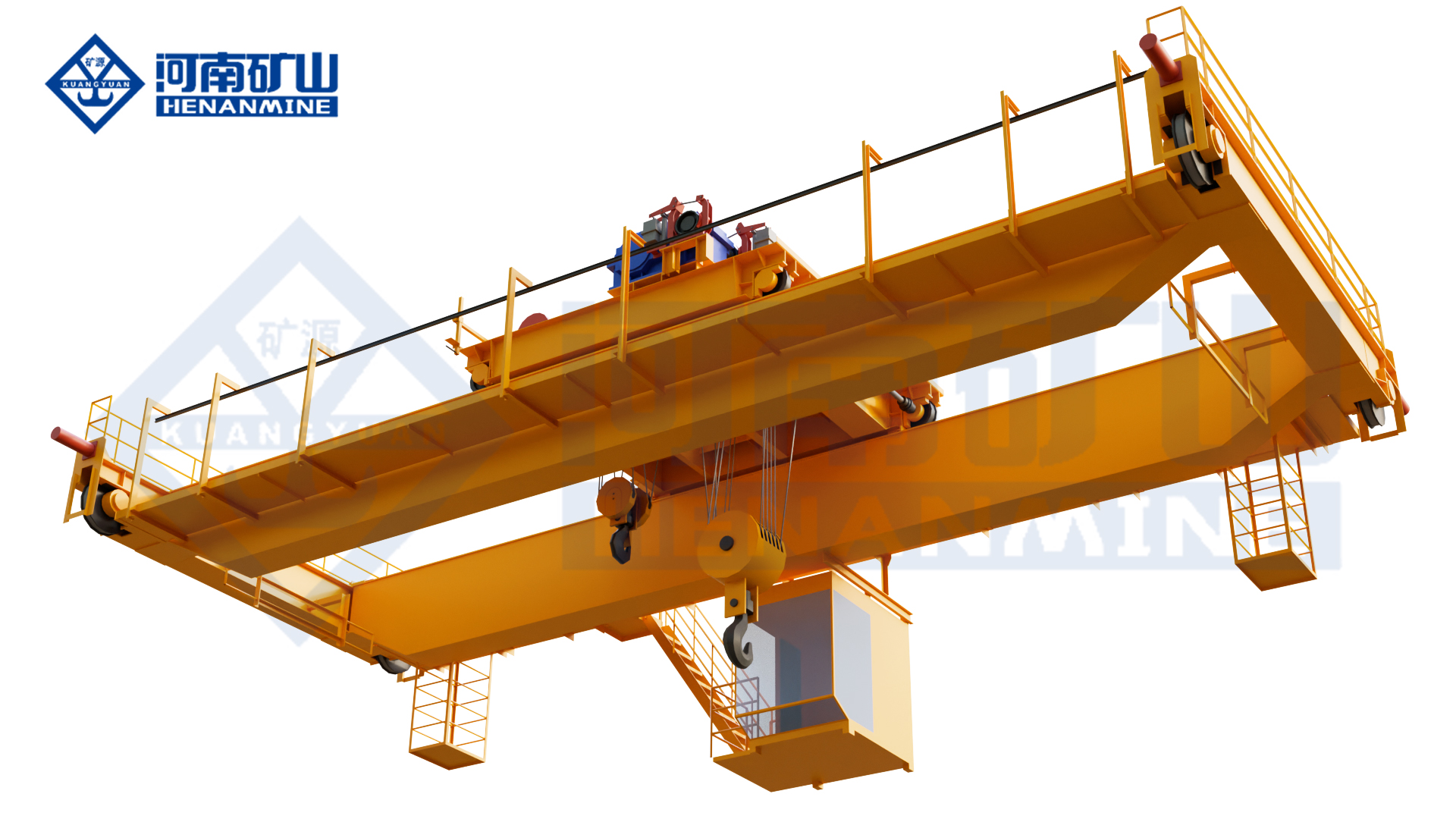
    Henan Mine CraneDiscuss your requirements ↗
  • Copper Smelter Crane

    Copper Smelter Crane

    Copper Smelter Crane

    Henan Mine Crane · Lifting Systems for Copper Smelters and Refineries

    Copper Smelter Crane

    Engineered crane systems for furnace and converter service, molten copper or slag-vessel transfer, anode handling, electrolytic tankhouse operations, bulk-material movement and plant maintenance.

    Henan Mine Crane configures each copper smelter crane around the actual process task, handled load, attachment, travel route, production cycle, runway, heat exposure, dust, fumes, corrosion, control philosophy and destination compliance requirements.

    copper smelter crane configured from a heavy-duty metallurgical bridge crane platform
    Copper plants require task-specific crane structures, lifting devices, protection systems and controls for each production area.

    PROCESS AREAS

    Smelter, Anode Plant, Tankhouse & Maintenance

    HANDLING DUTIES

    Vessels, Anodes, Cathodes, Bulk Materials & Equipment

    DESIGN CONDITIONS

    Heat, Dust, Fumes, Corrosion & Intensive Duty

    PRICE BASIS

    Engineered Project Quotation

    What Is a Copper Smelter Crane?

    A copper smelter crane is an overhead or process crane engineered for material handling within copper smelting, fire-refining, anode casting, electrorefining and supporting maintenance operations. The term describes an application family rather than one standard crane model. A machine that transfers a hot vessel near a furnace has a different risk profile, attachment and redundancy requirement from a crane that positions anode and cathode plates in an electrolytic cell.

    An integrated copper complex may therefore require several crane types: a metallurgical crane for high-consequence vessel handling, a grab crane for approved bulk materials, a purpose-built electrolytic copper or tankhouse crane with a multi-plate spreader, an insulated or corrosion-protected crane for defined special zones, and conventional double-girder cranes for maintenance loads.

    The purchase specification must begin with the process duty and load route. Capacity, span and lifting height remain important, but they do not define the required crane without the vessel drawing, attachment tare, load temperature, operating cycle, environmental measurements, availability target, control mode and supply boundary.

    Copper Smelter Crane Types

    01 · Molten Copper and Vessel Handling Crane

    A heavy-duty metallurgical overhead crane for a defined ladle, crucible, slag pot or transfer vessel. The design considers gross suspended load, trunnion or lifting-beam interface, center of gravity, route, radiant heat, motion control, braking, redundancy and emergency load-set-down procedure.

    02 · Charging and Bulk-Material Crane

    A grab, bin or hook crane selected for concentrates, fluxes, returns, slag or other approved bulk materials. Material bulk density, particle size, temperature, abrasiveness, moisture, dust behavior, required throughput and receiving equipment determine the attachment and crane duty.

    03 · Anode Handling Crane

    A crane for lifting cast copper anodes between the casting area, cooling or preparation stations, storage and tankhouse logistics. The lifting beam or gripper is matched to anode geometry, quantity per lift, spacing, surface condition and required orientation.

    04 · Electrolytic Copper Tankhouse Crane

    A process crane with a specialized spreader for grouped anode and cathode handling. It can be configured for cell loading and unloading, plate transfer, stacking and maintenance support, with positioning, corrosion protection, wash-down compatibility and automation selected for the refinery process.

    05 · Insulated or Special-Environment Crane

    Where the electrical study identifies credible current paths or the zone has exceptional corrosive exposure, an insulated or specially protected crane may be required. Insulation barriers, coating system, materials, enclosures and testing are defined from verified plant conditions rather than assumed from the industry name.

    06 · Maintenance and Auxiliary Crane

    A double-girder or electric-hoist bridge crane for furnace components, pumps, motors, ducts, molds, tools and shutdown maintenance. This configuration is economical for general lifting but must not be substituted for molten-metal or automated tankhouse duties.

    Compare Copper Smelter Crane Configurations

    The correct configuration follows the load consequence, process function and operating environment. One nominal capacity can describe several machines that are commercially and technically incompatible.

    Crane Configuration Primary Duty Typical Lifting Device Critical Design Basis Not a Substitute For
    Metallurgical Vessel Crane Transfer of a defined hot vessel or high-consequence suspended load Gantry hook, plate hook, lifting beam or vessel-specific interface Gross load, vessel drawing, heat, duty, route, redundancy and emergency procedure Tankhouse plate handling or routine light maintenance
    Grab or Charging Crane Bulk-material receipt, charging, transfer or slag handling Mechanical or powered grab selected for the material Material data, throughput, grab fill, dust control and receiving interface Molten-metal vessel handling or precision plate movement
    Electrolytic Copper Crane Anode and cathode loading, unloading, transfer and stacking Multi-plate spreader, gripper or project-specific lifting beam Plate geometry, cell pitch, positioning, corrosion, wash-down and automation Hot-vessel transport near furnaces or converters
    Insulated Bridge Crane Approved handling near defined electrical hazards Hook, beam or maintenance fixture Electrical study, current paths, insulation architecture and test plan A tankhouse process crane unless fitted with the required plate-handling system
    Maintenance Bridge Crane Equipment removal, shutdown work and general material handling Hook, maintenance beam or removable fixture Maximum maintenance load, hook coverage, headroom, frequency and environment Continuous process duty or high-consequence molten-load handling

    Selection principle: specify each crane by process duty and load consequence. A standard hook crane cannot become a tankhouse process crane by adding a plate beam, and a general double-girder crane should not be treated as a molten-metal crane without the required structural, mechanism, control and safety engineering.

    Match the Crane to the Copper Process Area

    A plant-wide handling study identifies every pickup point, destination, process time, attachment, operating envelope and interface. It also separates duties that cannot share one machine because of load consequence, contamination, corrosion, incompatible attachments or required availability.

    For furnace and converter areas, the study records the vessel or pot drawing, gross mass, contents, temperature, trunnions, lifting points, travel route, pouring or tipping requirement and safe set-down locations. For the anode and tankhouse areas, it records plate dimensions, plate quantity per lift, cell pitch, aisle geometry, stacking arrangement, washing sequence and production cycle.

    Maintenance loads, building clearances, runway capacity, fume extraction, electrical zones, access platforms and shutdown windows complete the design basis. The result is a crane responsibility matrix rather than one generic plant-wide specification.

    metallurgical overhead crane platform for copper smelter vessel and process handling
    The crane structure, hoisting system and attachment are selected from the actual vessel, process route and operating environment.
    Process Area Handling Task Crane Starting Point Essential Project Data
    Concentrate and charge area Bulk receiving, blending, stock movement and charging support Grab, bin or hook crane Material properties, throughput, pile geometry, pickup and discharge interfaces
    Smelting and converting Hot vessel, matte, slag-pot or process-equipment transfer Heavy-duty metallurgical crane Vessel drawing, gross load, route, heat map, duty and emergency plan
    Anode furnace and casting Refined copper vessel transfer, anode casting support and plate logistics Metallurgical crane plus anode-handling equipment Metal/vessel data, anode geometry, cycle, casting layout and cooling route
    Electrolytic tankhouse Anode and cathode plate loading, unloading, transfer and stacking Electrolytic copper process crane Cell layout, plate drawing, pitch, batch size, cycle, corrosion and automation
    Maintenance and stores Component removal, workshop repair, tooling and spare-part handling Double-girder or electric-hoist bridge crane Maximum load, hook coverage, headroom, frequency and environmental exposure

    Technical Selection and Specification Framework

    A procurement specification should convert production requirements into measurable crane performance and clearly assign every plant interface. Each hoist, trolley, attachment or process tool may require a separate capacity, speed, duty and acceptance criterion.

    Specification Item Required Project Input Engineering Output Risk if Undefined
    Rated load and load case Product load, vessel or attachment tare, contents, center of gravity and operating orientation Rated loads by mechanism, load combinations, overload settings and structural design basis Undersized equipment or unnecessary capital cost
    Span, runway and wheel loads Rail centers, runway length, elevation, end approaches, building capacity and existing rail condition General arrangement, wheel-load schedule, rail interface, buffers and building forces Structural reinforcement, clearance conflict or delayed installation
    Attachment and coverage Vessel, anode, cathode or material drawings; pickup, process and set-down coordinates Lifting-device concept, hook approaches, trolley envelope and interference study The crane cannot engage, clear or place the load safely
    Duty and availability Cycles, load spectrum, shifts, annual hours, process takt time and standby philosophy Crane and mechanism classifications, thermal checks, fleet quantity and maintenance plan Premature wear, production restriction or excessive specification
    Environment and materials Ambient and radiant heat, dust, gases, acid mist, humidity, wash-down, altitude and zone classification Materials, coating, sealing, enclosure, cooling, ventilation, cable and sensor selection Corrosion, overheating, unreliable controls or shortened service life
    Control and automation Manual tasks, automatic sequences, positioning, identification, plant network and data ownership Control modes, permissions, interlocks, HMI, communications and recovery logic Scope gaps between crane, process and plant-control suppliers
    Compliance and acceptance Destination law, purchaser standard, inspection authority, witness points and production-test availability Code matrix, inspection and test plan, FAT, site tests and handover document register Unclear compliance, repeated tests or contractual dispute

    Protection, Controls and Safety for Copper-Plant Conditions

    High-Consequence Suspended Loads

    Molten-metal or slag-vessel duties require a load-consequence review covering hoist arrangement, brakes, limits, overload protection, rope path, attachment retention, emergency power-loss response and approved set-down areas.

    Heat and Thermal Exposure

    Radiant heat and hot-air exposure are evaluated at the bridge, trolley, cabin, electrical enclosures, cables, sensors, lubricants and lifting device. Shields, separation, cooling and heat-resistant components follow measured conditions.

    Fumes, Acid Mist and Corrosion

    Coating systems, stainless or corrosion-resistant parts, sealed enclosures, cable materials, fasteners and ventilation are selected from the verified gas, mist, humidity and wash-down exposure in each operating zone.

    Dust and Material Containment

    Dust-resistant housings, protected brakes and drives, suitable filtration and interfaces to plant extraction limit contamination. Bulk-material attachments are selected to reduce uncontrolled release at pickup and discharge points.

    Stable Motion and Positioning

    Variable-frequency motion, controlled acceleration, braking, anti-sway functions, position feedback and travel zoning support predictable vessel transfer and plate placement. Required accuracy is stated at the actual load interface.

    Operator and Maintenance Access

    Cabin position, remote stations, cameras, alarms, access platforms, isolation points, rescue provisions and component replacement routes are coordinated with visibility, heat exposure and the plant work-permit system.

    PLC controlled process crane platform adaptable to copper smelter and refinery duties
    Control architecture, motion profiles and plant communication are configured around the approved copper-production sequence.

    Electrolytic Copper Crane and Tankhouse Automation

    In an electrorefinery, the crane is part of the production system rather than a general hook crane. The spreader must engage the specified number of anodes or cathodes, maintain the required pitch and orientation, clear the cell and busbar arrangement, and place plates without unacceptable contact or distortion.

    Manual, assisted, semi-automatic and higher-automation operating concepts are possible. Position feedback, cell identification, automatic travel paths, restricted zones, spreader permissions, load confirmation, anti-sway control, plate-washing interfaces and production-data exchange can be integrated where the refinery layout and process controls support them.

    The quotation should define the boundary between crane automation, lifting-device controls, cell management, wash equipment, anode preparation, cathode stripping, conveyors and the plant supervisory system. Undefined interfaces are a major source of commissioning delay.

    Relevant Heavy-Metallurgy Project Reference

    360-Ton Four-Girder Foundry Crane Project

    Henan Mine Crane published a 360-ton foundry-crane project supplied for Jinsheng’an Group. The machine uses a four-girder, four-rail, dual-trolley architecture for an ultra-heavy molten-metal duty, with structural analysis, balanced wheel-load distribution, redundant main-hoist arrangements, multiple braking and limit protections, thermal shielding and monitored controls.

    The project is relevant evidence of heavy metallurgical engineering, manufacturing and commissioning capability. It is not presented as a copper-smelter operating reference. A copper project still requires independent verification of the vessel, copper-process route, temperatures, fumes, corrosion, runway, duty and purchaser standards.

    For copper-smelter procurement, the transferable engineering disciplines are load-path analysis, structural redundancy, high-temperature protection, manufacturing traceability, factory testing and controlled site commissioning—not automatic reuse of the same 360-ton configuration.

    View the 360-Ton Metallurgical Crane Project →

    360 ton four girder foundry crane heavy metallurgy project by Henan Mine Crane
    Published heavy-metallurgy reference demonstrating four-girder structural, hoisting and thermal-protection engineering.

    Engineering Deliverables and Quality Records

    A procurement-ready proposal defines crane performance, process and building interfaces, inspection, acceptance and site responsibilities. Documents should remain traceable from approved inputs through manufacturing, factory testing, installation and commissioning.

    Design Basis

    Approved load and process schedule, duty calculations, general arrangement, attachment envelope, wheel loads, environment, utilities, code matrix and responsibility boundary.

    Control Documentation

    Electrical diagrams, PLC and network architecture, operating modes, interlock matrix, alarms, safe states, recovery logic and plant communication schedule.

    Manufacturing Records

    Material traceability, welding procedures, welder qualifications, dimensional inspection, NDT records, machining checks, coating reports and component certificates as contracted.

    Factory Acceptance

    Drive, brake, limit, overload, alarm and interlock tests; attachment functions; control modes; communications; simulated sequences and purchaser witness points.

    Review Henan Mine Crane manufacturing and quality capabilities →

    Installation, Commissioning and Lifecycle Planning

    Site Readiness

    Confirm runway survey, rail condition, building reserve, erection route, laydown area, power, extraction interfaces, access controls, shutdown window and hot-work restrictions before shipment.

    Installation

    Bridge and trolley assembly, rail and conductor checks, cabin and platform installation, lifting-device integration, utilities and plant-network connections follow approved method statements.

    Commissioning

    Testing progresses from no-load motions and safety functions to proof testing, dry sequence simulation and controlled production trials. Loads, materials, witness points and acceptance values are agreed beforehand.

    Lifecycle Support

    Training covers operation, attachment change, isolation, alarms, recovery and inspection. Preventive maintenance is organized by structure, mechanisms, controls, lifting device and environmental protection.

    Copper Smelter Crane Price and Supply Scope

    A copper smelter crane has no reliable universal list price. Current public advertisements cover machines with different capacities, structures and included scopes. They rarely define the process attachment, duty, corrosion protection, runway, controls, testing, freight, installation or commissioning.

    Publicly Advertised Category Observed Advertised Price Commercial Interpretation
    100-ton foundry-type overhead crane listing Approximately US$48,512–US$800,520 per set Extremely broad advertisement; configuration, redundancy and included project scope must be verified
    100-ton double-girder metallurgical crane listing From approximately US$260,000 per set One advertised configuration; not a complete copper-smelter installation budget
    350-ton four-beam foundry crane listing Approximately US$569,460–US$2,056,000 per set Heavy metallurgical equipment range; vessel, duty, controls and delivery boundary remain decisive
    Electrolytic copper tankhouse crane or complete plant package Project quotation Requires plate, cell, spreader, corrosion, automation, interface and acceptance data

    These figures are public market advertisements, not Henan Mine Crane quotations, average transaction prices, landed costs or turnkey project budgets. A valid comparison requires the same technical data sheet and responsibility matrix.

    Crane and Lifting Device

    Bridge, trolley, hoists, vessel interface, grabs, spreaders, hooks, cabins, platforms and maintenance access.

    Controls and Protection

    Drives, PLC, positioning, anti-sway, communications, automation, heat protection, corrosion protection and cameras.

    Delivery and Services

    Engineering, documents, inspection, FAT, packing, freight, insurance, spares, installation, commissioning and training.

    Plant Interfaces

    Runway, rails, conductor system, reinforcement, extraction, utilities, network connection and production-trial support.

    Information Required for a Copper Smelter Crane Quote

    A complete inquiry allows the crane configuration, process interfaces, delivery scope and commercial exclusions to be evaluated together. Preliminary drawings are acceptable during concept design when unresolved values are clearly identified.

    01 · Plant and process area

    New plant, expansion or replacement; smelter, converter, anode plant, tankhouse, maintenance bay or material store; production schedule and crane role.

    02 · Building and runway

    Layout, sections, rail span, runway length, rail elevation, headroom, columns, end approaches, rail data and allowable wheel loads.

    03 · Loads and attachments

    Vessel, ladle, pot, anode, cathode, process material or maintenance-load drawings; gross mass, contents, temperature and lifting points.

    04 · Process route and coverage

    Pickup, operating and set-down coordinates; furnace, converter, casting, cell, wash, stacking or maintenance interfaces; obstacles and restricted zones.

    05 · Performance

    Required capacity, lift height, speeds, positioning, cycles per hour, shifts, annual hours, availability target and standby philosophy.

    06 · Environment

    Ambient and radiant heat, dust, gases, acid mist, humidity, wash-down, altitude, electrical hazards and hazardous-area classification where applicable.

    07 · Controls and utilities

    Power supply, control stations, manual or automatic modes, plant network, communication protocol, extraction, compressed air and other services.

    08 · Compliance and acceptance

    Destination country, governing codes, purchaser standards, inspection authority, witness points, FAT, load test and production-trial requirements.

    09 · Delivery and site scope

    Destination port or site, trade term, packing, freight, installation, commissioning, local labor, lifting equipment, training and production support.

    10 · Schedule and lifecycle

    Required delivery date, shutdown window, documentation language, recommended spares, maintenance capability, response expectations and support plan.

    Copper Smelter Crane FAQ

    Is a copper smelter crane one standard crane model?

    No. The term can cover molten-vessel cranes, charging or grab cranes, anode-handling cranes, electrolytic copper tankhouse cranes and maintenance cranes. The process duty determines the configuration.

    What is the difference between a smelter crane and a tankhouse crane?

    A smelter crane may handle hot vessels, bulk materials or furnace equipment. A tankhouse crane is a process machine for anode and cathode plates, requiring a specialized spreader, accurate positioning and corrosion protection.

    How is the crane capacity selected?

    Capacity includes the product, vessel or lifting-device tare and any process contents. Dynamic effects, operating orientation, off-center conditions and required redundancy are evaluated for the defined load cases.

    Can a general double-girder crane handle molten copper?

    Not by default. Molten-load service requires a project-specific review of the hoist, brakes, limits, controls, load path, attachment, heat protection, emergency response and applicable regulations.

    How is tankhouse corrosion addressed?

    The verified acid-mist, humidity, chemical and wash-down exposure guides coating, material, fastener, cable, enclosure, ventilation and maintenance-access selection. Generic paint specifications are insufficient.

    Can an electrolytic copper crane be automated?

    Yes. Depending on plant interfaces, options include automatic positioning, cell identification, sequence control, restricted zones, spreader permissions, plate confirmation, anti-sway and production-data exchange.

    Can an existing runway be retained?

    Only after the rail geometry, alignment, support condition, wheel-load capacity, longitudinal forces, clearances and erection access are checked against the proposed crane and operating load cases.

    Does every copper plant need an insulated crane?

    No. Insulation is specified when the electrical study identifies credible current paths and required isolation. Corrosion protection, electrical insulation and explosion protection are separate design questions.

    Why do advertised copper smelter crane prices vary widely?

    Listings often omit the process attachment, duty, heat and corrosion protection, automation, runway, testing, delivery and commissioning. The same nominal tonnage can represent fundamentally different equipment.

    What should final acceptance include?

    Acceptance should cover documentation, visual and dimensional inspection, safety functions, load testing, lifting-device operation, controls, communications, dry process simulation, production trials, training and handover records as contracted.

    Request a Copper Smelter Crane Proposal

    Submit the process area, plant layout, load and lifting-device data, runway geometry, operating cycle, environmental measurements, control scope and delivery destination. Henan Mine Crane will prepare a project-specific configuration and commercial proposal.
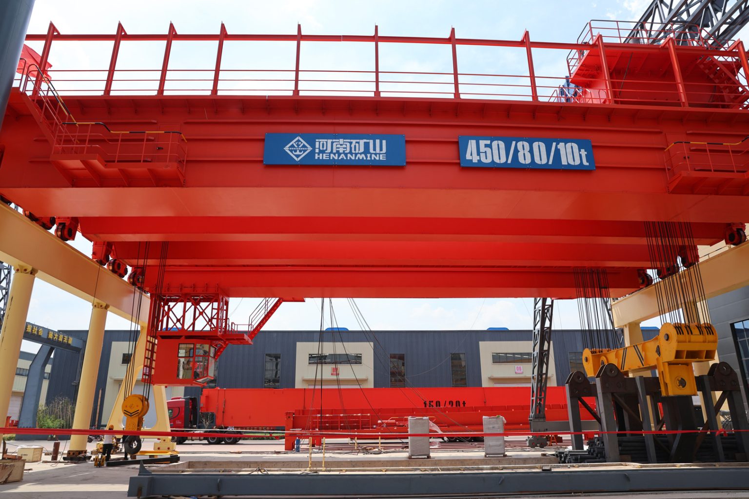
    Henan Mine CraneDiscuss your requirements ↗
  • Copper Smelter Crane Systems

    Copper Smelter Crane Systems

    Copper Smelter Crane Systems

    Henan Mine Crane · Non-Ferrous Metallurgical Lifting Systems

    Copper Smelter Crane Systems

    Process-duty overhead cranes for copper concentrate and flux handling, furnace charging, matte and slag pots, blister-copper transfer, anode-furnace service, casting operations, tankhouse handling and plant maintenance.

    Henan Mine Crane configures each copper smelter crane from the actual process zone, gross suspended load, vessel and attachment geometry, duty cycle, molten-material risk, heat and fume exposure, corrosion data, runway capacity, control philosophy and governing standards.

    double-girder metallurgical crane platform for copper smelter molten-material handling
    Copper smelter crane engineering begins with the process load and hazard in each bay; one crane design cannot cover concentrate, molten copper and tankhouse duties without separate validation.

    PROCESS AREAS

    Feed, Smelting, Casting & Refining

    CRANE TYPES

    Grab, Bin, Casting & Maintenance

    PRIMARY EXPOSURES

    Heat, Dust, Fumes & Corrosion

    PROJECT BASIS

    Process, Load, Duty, Route & Risk

    What Is a Copper Smelter Crane?

    A copper smelter crane is a process-specific overhead lifting system used across primary copper smelting, secondary copper production or electrolytic refining. Depending on the process, it may move bulk concentrate and flux, charge boxes, matte or slag pots, molten blister copper, anode-furnace vessels, casting equipment, copper anodes and cathodes, furnace components or maintenance loads.

    The term describes an application family rather than one standard machine. A grab crane for dry concentrate uses a different hoist, attachment and environmental package from a casting crane carrying a full vessel of molten copper. A tankhouse process crane uses mechanical lifting frames and corrosion protection, while a maintenance crane may operate only during shutdowns at a much lower load spectrum.

    Henan Mine Crane develops these systems from its intelligent grab crane, metallurgical bin crane, double-girder casting crane, four-girder casting crane and general double-girder platforms according to the declared copper process.

    Copper Smelter Crane Applications by Process Area

    The crane schedule should follow the flowsheet and separate routine process lifts from maintenance lifts. The processing route varies between flash smelting, bath smelting, batch converting, continuous converting, secondary smelting and other technologies, so the actual plant process remains the design basis.

    Concentrate and Flux Handling

    Grab and transfer concentrate, silica flux, coke, recycled material or other approved bulk feed between storage, blending, bins and process interfaces.

    Furnace Charging and Bin Transfer

    Lift, position and empty charge boxes or bins through a controlled sequence coordinated with furnace doors, hoods, feeders and exclusion zones.

    Matte and Slag Pot Transfer

    Move declared molten or semi-molten vessels between furnace, converter, slag-cleaning and cooling positions using a purpose-designed load path and vessel attachment.

    Blister Copper and Anode Refining

    Support vessel transfer, furnace service and maintenance from converting through anode refining, with heat protection and interlocks matched to the operating route.

    Anode Casting and Product Handling

    Handle casting equipment, molds, ladles, anodes and maintenance assemblies around the casting wheel or mold line without conflicting with hot-metal routes.

    Electrorefinery Tankhouse

    Transfer anode and cathode groups, stripping-line loads or cell-service equipment with mechanical lifting frames, corrosion protection and busbar clearances.

    Acid Plant and Off-Gas Systems

    Provide maintenance lifting for fans, ducts, pumps, heat exchangers and process equipment with protection based on measured chemical exposure and area classification.

    Shutdown and Major Maintenance

    Remove furnace, converter, hood, electrode, burner, pump or drive components using planned maintenance clearances, drop zones and laydown areas.

    intelligent grab overhead crane platform for copper concentrate and flux handling
    Bulk-feed cranes are sized from material density, moisture, abrasiveness, grab volume, fill factor, required throughput and the complete operating route.

    Copper Smelter Crane System Architecture

    1. Bridge and runway interface: transfer vertical, lateral, longitudinal, buffer and fatigue loads to the smelter building while maintaining furnace, hood and duct clearances.
    2. Process trolley and hoist: provide the main and auxiliary capacities, reeving, braking, drives, speed range and duty required for the declared vessel or material cycle.
    3. Load-handling device: connects to a charge box, pot, ladle, lifting trunnion, anode or cathode frame, grab, mechanical clamp, hook or maintenance spreader.
    4. Thermal and environmental package: protects structure, ropes, brakes, motors, panels, sensors and cab from radiant heat, dust, fumes, acid mist, condensation and corrosion.
    5. Safety and control system: coordinates limits, load monitoring, brakes, collision protection, restricted zones, process interlocks, safe states and controlled recovery.
    6. Power and plant interface: covers crane electrification, emergency-energy philosophy, PLC communication, operating modes, event records and interfaces with furnace, converter or casting equipment.
    heavy-duty metallurgical crane machinery for copper smelter process duty
    Structure, hoisting system, vessel attachment, thermal protection, controls and building reactions are engineered as one process system.

    Rated-load basis: capacity is based on the maximum gross suspended load. For a molten-material lift, include the vessel, refractory lining, maximum process contents, skull or adhered material where applicable, gantry beam or lifting frame, hooks, ropes and every suspended accessory. Main and auxiliary hook loads, tipping geometry and simultaneous operation require separate load cases.

    Copper Smelter Crane Selection Considerations

    Selection begins with the process function and credible operating cases. Nominal lifting capacity does not establish the required hoist redundancy, duty, attachment, heat protection, corrosion system or safe route.

    Process and Load Matrix

    Material or vessel identity, empty and full mass, temperature, dimensions, center of gravity, trunnions, attachment, normal cycle, abnormal condition and maintenance lifts.

    Production Duty

    Lifts per heat or batch, starts per hour, average and maximum load, travel distance, shifts, annual hours, standby time, production consequence of outage and maintenance window.

    Load Path and Interfaces

    Pickup, transfer and placement coordinates; furnace or converter status; casting equipment; vehicle crossings; occupied areas; emergency landing positions and interlocked machinery.

    Environmental Data

    Ambient and radiant temperature, duration of heat exposure, dust composition, SO₂ and acid mist, humidity, condensation, corrosive chemicals, washdown and hazardous-area classification.

    Building and Runway

    Rail-center span, runway length and elevation, headroom, hook approaches, wheel-load limits, clearances to ducts and hoods, expansion joints, rail condition and erection access.

    Safety and Acceptance

    Applicable law and standard, required redundancy, failure-response philosophy, operator location, access control, inspection route, representative-load tests and measurable process acceptance.

    Copper Smelter Crane Configurations Compared

    Each configuration addresses a different process load. Similar-looking bridge structures can contain materially different hoists, braking systems, attachments, controls and environmental protection.

    Configuration Typical Copper-Plant Duty Load-Handling Device Critical Definition
    Intelligent Grab Overhead Crane Concentrate, flux, coke, return materials or approved dry bulk feed. Four-rope or application-specific grab. Material density, moisture, abrasiveness, grab fill factor, dust control and required tonnes per hour.
    Metallurgical Bin or Charge-Box Crane Lifting, transferring and dumping charge boxes or process bins near a furnace. Forged hook, gantry attachment or custom box interface. Box geometry, tipping sequence, furnace-door and hood interlocks, heat exposure and spill boundary.
    Double-Girder Casting Crane Molten matte, slag, blister copper or anode copper vessel transfer within its engineered range. Gantry-type ladle beam or vessel attachment, with auxiliary hook where required. Gross vessel load, trunnions, main and auxiliary capacity, redundancy, heat protection and emergency landing.
    Four-Girder, Multi-Rail Casting Crane Ultra-heavy or intensive molten-material duty requiring main and auxiliary trolleys. Main gantry attachment plus auxiliary forged hook. Trolley interaction, tipping load cases, wheel-load distribution, runway capacity and maintenance access.
    Tankhouse Process Crane Anode and cathode group transfer, cell service and stripping-line interfaces. Mechanical frame, hooks, clamps or custom group-lifting device. Plate spacing, electrolyte carryover, busbar clearance, electrical isolation strategy, corrosion and drip control.
    General Double-Girder Maintenance Crane Furnace, converter, hood, pump, fan and drive maintenance during planned access. Hook, sling or maintenance spreader. Heaviest maintenance assembly, infrequent-load spectrum, laydown area and shutdown access. Not a molten-metal crane unless specifically engineered and approved.

    Copper is not a ferromagnetic lifting load: ordinary electromagnetic lifting magnets used for steel do not provide the required holding method for copper anodes, cathodes, plate or scrap. Copper-product handling requires hooks, mechanical clamps, lifting frames, grabs or another engineered mechanical attachment.

    metallurgical bin crane for copper smelter furnace charging and material transfer
    A bin or charge-box crane is selected from the actual container, tipping method, furnace interface and thermal exposure.
    double-trolley charge box crane for a non-ferrous metal smelting plant
    Two-trolley arrangements are considered when synchronized support, turnover or separate process functions are required.

    Published Metallurgical Crane Platform Ranges

    The following Henan Mine Crane product-page data provides an initial platform reference. These are not preselected copper-smelter specifications. Final capacity, span, lift, class, speeds, redundancy and attachment are determined by the approved process data.

    Published Platform Published Capacity Published Span Published Lift Published Class
    Intelligent Grab Double-Girder Overhead Crane 5–50 t 10.5–31.5 m 6–30 m A6–A8
    YX Metallurgical Bin Crane 5–50 t 7.5–35 m 6–20 m A6–A7
    Double-Girder Casting Crane 50–125 t in the published parameter table; customized 10–35 m 6–25 m A7 published; page header notes A7–A8 options
    Four-Girder Casting Crane 200/50–500/200 t published header range 10–40 m 6–30 m A7–A8 published header range
    Published ranges describe product platforms. They do not authorize any molten-copper lift until the vessel, process contents, attachment, load path, duty, redundancy and local compliance basis are reviewed and accepted for the project.

    Copper Smelter Load Attachments

    The lifting device is part of the process system. Its geometry, rating, heat exposure, inspection method and failure consequences should be included in the crane design and acceptance plan.

    Attachment Typical Load Engineering Checks
    Four-Rope Grab Concentrate, flux and approved dry bulk material. Bulk density, moisture, particle size, cohesiveness, abrasion, grab fill factor and closing force.
    Charge-Box or Bin Attachment Furnace feed boxes, bins and containers. Pickup points, latch confirmation, turnover angle, retained material, furnace clearance and release sequence.
    Gantry Ladle Beam or Vessel Hook Matte, slag, blister-copper or anode-copper vessels. Trunnion profile, seating, side clearance, vessel tilt, refractory and contents mass, heat shielding and inspection access.
    Auxiliary Hook or Tipping Device Controlled pouring, vessel rotation and maintenance assistance. Load sharing through the complete angle range, synchronization, rope fleet, prohibited positions and interlocks.
    Anode and Cathode Lifting Frame Individual plates or defined groups in the tankhouse. Plate pitch, mass variation, engagement confirmation, busbar clearance, electrolyte drainage and short-circuit prevention.
    Maintenance Hook and Spreader Furnace, converter, hood, pump, fan, motor and structural components. Approved lifting points, center of gravity, headroom, laydown position, sling angle and shutdown sequence.
    gantry lifting attachment on a metallurgical overhead crane for molten-metal vessel transfer
    Molten-material lifting devices are checked against the actual vessel trunnions, full operating mass, thermal exposure and complete transfer sequence.

    Molten-Material Safety and Failure Response

    A molten-copper crane is a process-safety system, not a general overhead crane with additional heat shields. The design basis must define what occurs after loss of one motor, reducer, brake, rope path, encoder, controller, incoming supply or communication link. The required redundant architecture depends on capacity, process risk, local law and the selected design standard.

    • Specify the main-hoist load path, service and emergency braking arrangement, upper-limit architecture and overspeed or unintended-motion protection where required.
    • Define whether a remaining drive can hold, lower or complete a controlled safe-placement cycle after a single failure.
    • Provide a predetermined landing or containment position for a retained molten load; emergency energy must have a stated function and duration.
    • Keep routine travel away from occupied rooms, control stations, escape routes and water hazards wherever the plant layout permits.
    • Interlock vessel transfer with furnace, converter, hood, door, aisle and casting equipment states as defined by the process hazard review.
    • Prohibit tandem or simultaneous operations unless the cranes, controls, load-sharing method and lift plan are engineered for that operation.
    four-girder high-temperature metallurgical crane for intensive molten-material service
    Four-girder, multi-rail arrangements are evaluated for ultra-heavy loads, trolley coordination, torsional demand and runway wheel-load distribution.

    Safety boundary: no personnel route should pass beneath a suspended vessel or load. The plant risk assessment defines access control, molten-material exclusion areas, spill response, emergency communications and restart authorization.

    Heat, Dust, Fume and Corrosion Protection

    Environmental protection should be zoned from measured exposure. Furnace-bay thermal radiation, concentrate dust, converter fumes, tankhouse acid mist and acid-plant chemicals do not produce the same failure mechanisms.

    Thermal Protection

    Heat shields, insulated structural zones, protected ropes and drums, high-temperature cables, suitable lubricants, remote panels and component-temperature monitoring are selected from exposure and duration.

    Dust Management

    Enclosures, filtration, positive-pressure cabinets, sealed bearings, accessible cleaning points and cable routing are matched to dust loading, conductivity and abrasion.

    Fume Exposure

    Cab location, filtered pressurization, HVAC intake position, remote operation, viewing systems and escape route are coordinated with SO₂ and other process-fume mapping.

    Corrosion System

    Surface preparation, coating, fasteners, enclosure materials, seals and corrosion allowance are chosen from chemical concentration, temperature, condensation and maintenance practice.

    Tankhouse Electrical Interface

    Busbar clearance, grounding, isolation, conductive-liquid carryover, prohibited bridging paths and fault-current consequences require coordination with the plant electrical design.

    Hazardous Areas

    Explosion-protected equipment is selected only from a documented zone, gas or dust group, temperature class and protection concept. A copper smelter is not automatically one uniform hazardous area.

    protected automatic metallurgical crane system for hot dusty and corrosive process environments
    Protection level, cooling, sealing, coating and control-cabinet location are selected separately for each smelter bay.

    Controls, Interlocks and Process Integration

    Operating Mode Primary Use Required Definition
    Cabin Control Intensive furnace, converter or molten-vessel handling with a protected operator station. Sight lines, camera coverage, fume protection, HVAC, emergency exit, alarms and communication.
    Radio or Local Control Maintenance and selected process moves where a safe operator position provides better visibility. Permitted zones, transmitter authorization, emergency stop coverage and mode-transfer interlocks.
    Assisted Operation Operator-initiated moves with protected routes, anti-sway, positioning or automatic approach. Control authority, target confirmation, obstacle response, restricted-zone logic and manual recovery.
    Automatic Operation Repeatable bulk-feed or defined production routes with controlled access and reliable process signals. Task handshake, permissives, safe states, sensor coverage, communication loss, exception handling and restart approval.

    A process signal matrix should identify command ownership and permissives for furnace doors, converter position, hoods, feeders, casting machines, aisle gates, other cranes and maintenance access. Event records should distinguish operator command, process refusal, safety trip, device fault and communication failure. Automatic operation does not remove the need for a verified local recovery procedure.

    Runway, Building and Maintainability Interfaces

    Wheel Loads and Fatigue

    Provide maximum, minimum and concurrent trolley wheel loads, lateral and longitudinal forces, buffers, fatigue spectrum and rail tolerances for structural verification.

    Process Clearances

    Coordinate bridge depth, trolley envelope, vessel swing, hook approach, hoods, ducts, stacks, columns, access platforms and operating equipment in every position.

    Runway Survey

    For an existing building, survey rail gauge, elevation, alignment, joints, wear, fasteners, beams, brackets, columns and foundations before final crane reactions are accepted.

    Maintenance Access

    Define platforms, guardrails, walkways, lighting, isolation points, component-removal routes, trolley service position and lifting points for crane maintenance.

    Critical Spares Strategy

    Identify brakes, ropes, wheels, bearings, encoders, drives, PLC modules, contactors, sensors, seals and attachment wear parts from production consequence and replacement lead time.

    Erection and Outage Plan

    Establish delivery splits, access opening, site lifting method, temporary works, outage duration, hot-work restrictions, tie-in sequence and commissioning area.

    four-girder six-rail casting crane showing heavy metallurgical runway interfaces
    Heavy casting-crane selection must be coordinated with runway reactions, building stiffness, rail geometry and component-maintenance routes.

    Standards, Inspection and Acceptance Testing

    The contract should state the governing jurisdiction, standards and editions. A project basis may include ISO 4301 for classification, ISO 9927 for inspection, ISO 12480-1 for safe use, EN 13001 and EN 15011 for crane design, or CMAA 70 with ASME B30.2 requirements for the applicable overhead-crane arrangement. Electrical equipment may reference IEC 60204-32. Safety-related control systems may use ISO 13849-1 or IEC 62061 where applicable. Classified areas require the plant’s selected IEC 60079, ATEX, IECEx or local basis. Local law and the signed project specification remain controlling.

    Design Review

    Approve classifications, load cases, redundancy, structural and mechanism calculations, attachment drawings, wheel loads, environmental protection and safety functions.

    Manufacturing Records

    Define material traceability, welding procedure and personnel qualification, nondestructive examination, heat treatment, machining, assembly and coating records.

    Factory Acceptance

    Verify mechanisms, brakes, limits, overload system, control modes, alarms, process simulation, fault responses, interface signals and documentation before shipment.

    Site Acceptance

    Confirm runway geometry, commissioning tests, proof load, representative vessel or material handling, interlocks, protected routes, emergency functions and agreed production cycles.

    Published Heavy Metallurgical Crane Reference

    Henan Mine Crane has published a 360 t foundry-crane project reference for Jinsheng’an Group. The delivered crane uses a four-girder, four-rail, dual-trolley arrangement for ultra-heavy molten-metal service and incorporates project-specific structural, hoisting, braking and thermal-protection measures.

    The reference demonstrates manufacturing and commissioning experience with a large-capacity metallurgical crane, including trolley coordination, high wheel loads, heat exposure and molten-material risk controls. Henan Mine Crane also publishes a four-girder casting-crane platform for steel and non-ferrous smelting applications, explicitly including molten copper handling in its application description.

    A copper-smelter proposal would still be developed from the copper vessel, trunnion and attachment data; matte, slag or anode-copper process; plant layout; environmental measurements; required compliance basis and acceptance plan.

    published 360 ton four-girder metallurgical crane project reference
    Published adjacent reference: 360 t four-girder, four-rail, dual-trolley foundry crane.

    Evidence boundary: the published 360 t project is an adjacent heavy-metallurgical reference, not a stated copper-smelter delivery. It demonstrates relevant engineering and manufacturing disciplines but does not define the capacity, redundancy, duty, attachment, performance, savings or acceptance criteria of another project.

    Copper Smelter Crane Price and Budget Scope

    A copper smelter crane price is established from process risk and total supply scope, not tonnage alone. Molten-material redundancy, main and auxiliary trolleys, vessel attachment, thermal protection, corrosion system, runway work, plant interfaces, testing and erection can change the investment substantially.

    The public market review below was completed on 20 September 2026. Public listings can change and frequently omit decisive engineering information. They are market observations rather than directly comparable installed-project quotations.

    Public Reference Displayed Price Displayed Scope Commercial Boundary
    Henan Mine Crane supplier listing: YZ metallurgical foundry double-girder casting crane US$156,000 for 1–4 pieces; US$146,000 for 5+ pieces Configurable equipment listing; Qingdao port shown Capacity, span, vessel attachment, redundancy, freight, installation, runway and copper-process acceptance require a written proposal.
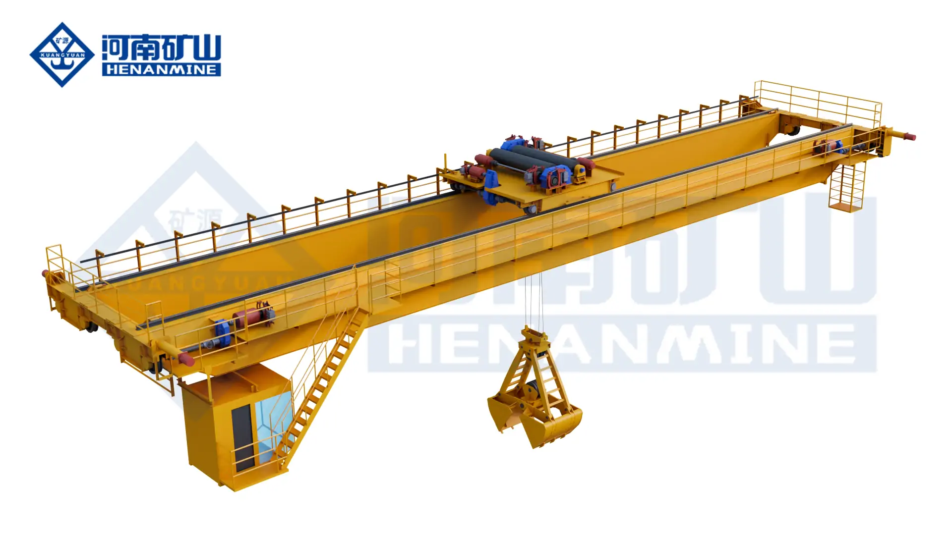
    Public listing: 400/100 t four-beam casting overhead crane US$80,000–500,000 per piece; MOQ 1 Heavy four-beam casting-crane listing Displayed range does not establish final configuration, compliance, engineering, attachment, shipping or installed scope.
    Public listing: 15 t grab-bucket overhead crane US$3,000 per set; MOQ 1 Generic grab-crane equipment reference Not comparable to an engineered smelter concentrate crane; grab, duty, dust controls, structure, electrification and site scope require confirmation.
    Complete copper smelter crane package Project-specific quotation One or more process cranes, attachments, controls, runway interfaces and services Requires the process load schedule, duty, layout, environmental data, risk basis, standards, destination and defined delivery boundary.

    Reference sources: public supplier listings on Made-in-China. The displayed values do not constitute an offer from this page and should not be used as an installed-project budget without a technical and commercial scope review.

    Main Cost Drivers

    Capacity and Duty
    Gross vessel load, main and auxiliary capacities, class, starts, speeds and annual hours.
    Safety Architecture
    Drive and brake redundancy, limits, load monitoring, emergency energy and safe-placement logic.
    Attachment
    Grab, charge-box device, gantry ladle beam, auxiliary hook or tankhouse lifting frame.
    Environment
    Heat shields, cooling, filtration, corrosion system, sealed equipment and protected cab.
    Civil and Electrical
    Runway, rails, strengthening, power supply, conductor system, platforms and access.
    Project Services
    Freight, inspection, erection, commissioning, load test, training, spares and documentation.

    Engineering and Procurement Deliverables

    A comparable bid separates crane performance, process interfaces and site services. The procurement package should identify deliverables and approval responsibilities before commercial comparison.

    Design Basis

    Process description, load cases, classifications, standards, redundancy philosophy, environment, reliability target, interfaces and exclusions.

    Calculation Package

    Structure, mechanisms, fatigue, ropes, drums, brakes, wheels, wheel loads, attachment, heat protection and safety-related controls as contractually required.

    Interface Drawings

    General arrangement, vessel and attachment, runway reactions, clearances, electrification, PLC signals, access, maintenance and erection splits.

    Inspection and Test Plan

    Hold points, traceability, welding records, nondestructive examination, factory tests, proof load, process simulation and site acceptance scenarios.

    Operating Documentation

    Manuals, inspection schedules, fault-response procedures, rescue and recovery, software backups, attachment register and operator training.

    Commercial Schedule

    Inclusions, exclusions, Incoterm, freight, civil work, erection, utilities, commissioning, spares, warranty, schedule and local support responsibility.

    Information Required for a Copper Smelter Crane Quote

    Complete enquiry data allows the crane, attachment, building interface, environmental protection and delivery scope to be selected and priced on one defined basis.

    Process and Load Data

    Smelting technology and process zone; material or vessel; empty, normal and maximum mass; temperature; dimensions; center of gravity; attachment and operating sequence.

    Vessel and Attachment Drawings

    Pot, ladle, bin, charge box, trunnion, tipping lug, anode/cathode frame, grab or spreader drawings with allowable contact and clearance zones.

    Duty and Production Cycle

    Cycles per heat or hour, shifts, annual hours, load spectrum, travel distances, simultaneous motions, speed targets, outage consequence and maintenance window.

    Plant Layout and Runway

    Plan and cross-section, span, runway length and elevation, rail data, wheel-load limits, process clearances, hot-load route, emergency position and installation access.

    Environment and Controls

    Ambient and radiant heat, dust, fumes, chemicals, humidity, corrosivity, hazardous-area classification, power supply, control mode, signals and plant communication protocol.

    Compliance and Commercial Scope

    Destination, standards, inspection route, Incoterm, freight, runway, installation, commissioning, load test, training, spares, documentation and warranty.

    Fastest route to a comparable proposal: submit the process flowsheet, lifting-equipment schedule, vessel and attachment drawings, workshop cross-section, load spectrum, environmental design data, runway information and required supply boundary. Unknown items can then be recorded as open points rather than hidden inside assumptions.

    Frequently Asked Questions

    Which crane is used in a copper smelter?

    Grab cranes handle dry bulk feed, bin cranes serve charge boxes, casting cranes handle approved molten-material vessels, tankhouse cranes move anodes and cathodes, and general double-girder cranes support maintenance. Each duty requires a separate specification.

    Can an electromagnetic crane lift copper?

    No conventional steel-lifting electromagnet should be specified for copper plate, anodes or cathodes because copper is not ferromagnetic. Mechanical hooks, frames, clamps, grabs or purpose-designed attachments are required.

    How is casting-crane capacity calculated?

    The basis is the heaviest gross suspended load: vessel, refractory, maximum process contents, adhered material, lifting beam, hooks and every accessory. Tipping, eccentric and simultaneous main/auxiliary-hook cases are evaluated separately.

    Is every copper smelter crane explosion-proof?

    No. Explosion protection is determined by the documented area classification, substance group, temperature class and selected protection concept. High temperature, corrosion resistance and explosion protection are different design requirements.

    What duty class is required?

    Molten-material and bulk-feed cranes commonly require high-duty classifications, while shutdown maintenance cranes may be lower duty. The correct class follows the load spectrum, cycles, speeds, annual hours and consequence of downtime.

    Can an existing runway be reused?

    Only after the rails, beams, brackets, columns, connections and foundations are surveyed and checked for condition, geometry, fatigue and the proposed vertical, lateral, longitudinal and dynamic reactions.

    How much does a copper smelter crane cost?

    Public listings reviewed in September 2026 included US$156,000 for one configurable foundry-crane listing and US$80,000–500,000 for a 400/100 t four-beam listing. A complete copper-smelter crane remains quotation-based because the published scopes are incomplete.

    What should be tested before handover?

    Testing should cover mechanisms, brakes, limits, overload protection, attachment engagement, representative loads, process interlocks, safe states, single-fault responses, emergency placement, proof load and agreed operating cycles.

    Request a Copper Smelter Crane Quote

    Submit the process area, maximum gross suspended load, vessel and attachment drawings, span, lift, operating cycle, environmental data, runway information, destination and required delivery scope. Henan Mine Crane will prepare a configuration and commercial proposal against the declared operating basis.

    Henan Mine CraneDiscuss your requirements ↗
  • Container Yard Crane

    Container Yard Crane

    Container Yard Crane

    Henan Mine Crane · Container Terminal and Intermodal Yard Systems

    Container Yard Crane

    Engineered RMG, RTG, straddle carrier and fixed container crane systems for marine terminals, dry ports, railway freight yards, inland logistics hubs and container depots.

    Henan Mine Crane configures each container yard crane around the container mix, rated load under spreader, block geometry, stacking height, truck or rail interface, peak move requirement, operating duty, power strategy, automation level and destination conditions.

    Henan Mine Crane rail mounted container yard crane operating above container stacks
    A container yard crane is selected as part of the terminal system. Crane geometry, yard block, stacking policy, landside interface, power and automation are engineered together.

    Applications
    Ports, dry ports, rail terminals, logistics hubs and depots

    Primary systems
    RMG, RTG, straddle carrier and fixed overhead crane

    Critical yard data
    TEU demand, rows, tiers, lanes, rehandles and peak moves

    Commercial basis
    Defined interfaces, supply scope and project quotation

    Container Handling Systems for Yard Stacking and Transfer

    A container yard crane lifts, stacks and transfers ISO containers between storage blocks, terminal tractors, road trucks and railway wagons. The term covers several equipment concepts rather than one standard machine. Rail-mounted gantry cranes provide dense, repeatable coverage over fixed blocks; rubber-tyred gantry cranes combine block stacking with yard mobility; straddle carriers combine transport and stacking; and fixed container overhead cranes serve indoor or structurally supported bays.

    The required machine cannot be selected from rated tonnage alone. The engineering basis includes 20 ft, 40 ft and 45 ft container proportions, loaded and empty weights, reefer and hazardous-container rules, single- or twin-lift operation, row count, stacking tiers, truck or rail lanes, cantilever arrangement, peak moves per hour, annual TEU, required availability and planned automation.

    A ship-to-shore crane transfers containers between a vessel and the quay and is not normally the yard-stacking machine. The container yard crane receives the flow from quay tractors, rail wagons or road vehicles and controls storage density and retrieval performance. The interface between these systems is therefore included in terminal planning even when the equipment is purchased under separate contracts.

    Container Yard Crane Configurations

    01 · Rail-Mounted Gantry Crane

    An RMG travels on fixed rails and spans container rows plus truck or railway lanes. It supports high stacking density, precise positioning, electric power and advanced automation. Rail foundations, block alignment, storm restraints and a fixed operating envelope are integral to the project.

    02 · Rubber-Tyred Gantry Crane

    An RTG runs on rubber tyres and can serve different yard blocks when the pavement, steering system and traffic plan permit. Diesel-electric, hybrid, battery or externally electrified arrangements may be evaluated. Mobility must be balanced against tyre care, route control, energy supply and block-change time.

    03 · Container Straddle Carrier

    A straddle carrier lifts, carries and stacks containers with one mobile machine. It can reduce fixed rail infrastructure and provide flexible transfer between quay, yard and landside interfaces. Fleet sizing, traffic separation, turning space, pavement loading, battery charging or fuel service and maintenance access govern the operating concept.

    04 · Container Overhead Crane

    A container overhead crane runs on an elevated building or freestanding runway above a fixed bay. It is suitable for indoor transfer, manufacturing logistics, specialized depots or controlled rail and truck interfaces where weather protection and unobstructed floor access are required.

    05 · Automated RMG or RTG System

    Remote or automated operation can integrate anti-sway, absolute positioning, container recognition, truck-lane guidance, path control, collision avoidance and terminal operating system communication. Automation scope is defined with network architecture, data ownership, cybersecurity, recovery modes and manual intervention points.

    06 · Intermodal and Rail Yard Crane

    An intermodal yard crane spans railway tracks, truck lanes and storage rows to transfer containers between railcars and the stack. Rail operating windows, wagon profiles, track clearances, locomotive restrictions, grounding, signaling interfaces and terminal peak schedules become part of the design basis.

    RMG vs RTG vs Straddle Carrier

    The correct container yard crane follows the terminal operating model. Fixed high-density blocks generally favor RMG systems; flexible blocks and phased development can favor RTGs; integrated transfer and stacking can favor a straddle-carrier fleet. A lifecycle comparison should include civil works, energy, tyres or rails, staffing, automation, fleet redundancy and maintenance—not equipment price alone.

    System Typical operating fit Primary strength Critical infrastructure Key purchasing issue
    RMG High-density fixed blocks, rail terminals, dry ports and automated yards Precise rail guidance, electric operation and strong automation potential Rails, foundations, electrical distribution, drainage and storm anchoring Fixed block geometry must be correct before manufacture
    RTG Marine and inland yards requiring block mobility or phased expansion Can relocate between compatible blocks without fixed travel rails Pavement, marked routes, tyre service and diesel, hybrid, charging or conductor infrastructure Energy strategy, steering accuracy and safe block-change procedure
    Straddle carrier Flexible transfer-and-stack operations and shorter horizontal moves One mobile unit carries and stacks without a separate terminal tractor Traffic lanes, turning space, pavement, fleet workshop and energy service Fleet availability, traffic control and whole-life maintenance
    Container overhead crane Indoor or fixed-bay container transfer and specialized industrial logistics Weather-protected operation with clear floor-level access Building runway or freestanding steelwork, foundations and power supply Building loads, clearances and fixed operating envelope
    Ship-to-shore crane Vessel-to-quay container transfer Quayside ship service and outreach over vessel bays Quay rails, berth structure, power and waterside clearances It is a quay interface, not a substitute for the yard-stacking system

    Selection rule: specify RMG equipment where fixed block density, repeatable positioning, electric operation and automation justify rail infrastructure. Specify RTG equipment where block mobility and phased yard development have greater value. Specify straddle carriers where integrated horizontal transport and stacking provide the required flexibility. Hybrid layouts can combine systems when quay, rail and landside flows have different operating demands.

    Yard Capacity, Stacking Height and Throughput

    Annual TEU establishes the overall demand but does not define the crane quantity or speed by itself. Equipment sizing uses vessel, rail and truck peaks; dwell-time distribution; import, export and empty-container balance; reefer and hazardous segregation; rehandle strategy; maintenance windows; and the availability target for the complete yard system.

    Theoretical yard slots = usable ground slots × permitted stacking tiers
    Required crane productivity = peak moves ÷ available operating hours, adjusted for rehandles and availability

    Practical storage capacity is lower than the theoretical maximum because operational headroom is required for segregation, reshuffling, equipment access, maintenance and peak imbalance. A high nominal stacking tier can also increase rehandles and retrieval time. The preferred 1-over-X arrangement is therefore confirmed with the operating model rather than selected only to maximize static capacity.

    Cycle modeling includes spreader approach and engagement, hoisting, trolley travel, gantry travel where applicable, anti-sway settling, truck or wagon alignment, twistlock confirmation, set-down, release and operational delay. Representative long and short travel cases are tested. A single guaranteed moves-per-hour figure is only meaningful after the block geometry and operating assumptions are agreed.

    Crane quantity should preserve the required service when one unit is under planned maintenance or when adjacent blocks experience simultaneous peaks. Terminal simulation or a documented cycle model can compare alternative row counts, transfer lanes, cantilevers, stacking policies and fleet sizes before the final equipment schedule is frozen.

    Container Yard Application Matrix

    Facility Preferred starting point Critical operating data Engineering focus
    Marine container terminal RTG, RMG or straddle-carrier system selected for the terminal concept Berth peaks, tractor flow, vessel exchange, stack occupancy and gate demand Quay-to-yard balance, corrosion, wind, traffic segregation and availability
    Dry port or inland terminal RMG for fixed high-density blocks; RTG for flexible phased development Train schedules, truck peaks, block length, expansion stages and power access Rail clearances, long travel, landside lanes, automation and future extension
    Rail intermodal yard Long-span RMG or mobile container handler fleet Track count, wagon profile, train length, lift windows and locomotive movement Rail signaling interfaces, electrification clearances and safe access control
    Empty-container depot RTG, straddle carrier or dedicated empty-container equipment Container tare range, stacking policy, inspection and repair flow High stacking utilization, lower payload, fast retrieval and damage control
    Reefer and hazardous zones Compatible yard crane with controlled access and segregated blocks Reefer rack layout, plug access, dangerous-goods classes and emergency plans Clearances, fire strategy, access routes, electrical protection and operating rules
    Industrial container logistics Container overhead crane, RMG or compact RTG Building or yard envelope, truck lanes, production schedule and load status Facility interfaces, headroom, foundations, controlled positioning and expansion

    Technical Specification Framework

    The specification is finalized from the container schedule, terminal layout, cycle model, environment and operating philosophy. Rated capacity under spreader, crane span, stacking height and working duty are important, but they do not define the complete container yard system.

    Henan Mine Crane converts the approved basis into a general arrangement, load and speed schedule, wheel or pavement reactions, spreader interface, power concept, control philosophy, safety-function schedule, data-interface list, inspection plan and itemized commercial boundary.

    Henan Mine Crane rubber tyred container yard crane arrangement
    Container rows, truck lane, stacking tiers, spreader type and power arrangement determine the RTG operating envelope.
    Specification item Required project input Engineering output
    Rated load under spreader Maximum gross container mass, single or twin lift and special loads SWL, spreader rating, overload strategy and structural design load
    Container interface 20 ft, 40 ft and 45 ft mix, ISO corner fittings and load status Telescopic spreader, twistlock monitoring, flippers and optional twin-lift arrangement
    Span and cantilevers Row count, track or lane widths, clearances and transfer position Rail or tyre centers, trolley travel, end approaches and landside coverage
    Lifting height 1-over-X stacking policy, vehicle or wagon height and required clearance Spreader path, rope travel, upper clearance and maintenance access
    Working duty Moves per hour, operating hours, load spectrum, availability and design life Crane and mechanism classifications with fatigue and thermal verification
    Motion performance Peak cycle requirement, travel distances and positioning tolerance Hoist, trolley and gantry speeds, acceleration, anti-sway and precision modes
    Power system Grid capacity, emissions policy, block mobility and energy objectives Cable reel, busbar, electric RTG, battery, hybrid or diesel-electric concept
    Control and automation Cabin, remote or automated operation and TOS/RCMS interface requirements PLC/VFD architecture, sensors, networks, data exchange and recovery modes
    Environment Temperature, wind, rainfall, humidity, salt fog, dust and seismic conditions Coating, enclosures, heating or cooling, wind limits and storm protection
    Codes and acceptance Destination regulations, purchaser specification and inspection requirements Agreed structural, crane, electrical and machine-safety code matrix and test plan

    Published Henan Mine Crane reference families include RMG and RTG container cranes with common rated loads of 35 t, 40.5 t and 50 t under spreader, project spans from approximately 8 m to 35 m, lifting heights from approximately 6 m to 21 m and A6–A8 working duty. Container straddle carriers are available in published reference ratings of 30–50 t with 1-over-3 to 1-over-6 stacking arrangements. Final values depend on the agreed container, yard, duty and code basis.

    Power, Automation, Safety and Environmental Protection

    Electric and Mobile Power

    RMG cranes commonly use cable reels or busbar systems. RTG and straddle-carrier projects can evaluate diesel-electric, hybrid, battery or externally electrified arrangements. Grid connection, charging demand, redundancy, cable routes, block mobility and lifecycle energy cost are reviewed together.

    Spreader and Load Confirmation

    Twistlock position, landed status, all-corners-locked confirmation, container size selection, load measurement and spreader cable management support controlled pickup. Interlocks prevent hoisting or travel when the defined engagement state is not achieved.

    Anti-Sway and Positioning

    Mechanical or electronic anti-sway, absolute position feedback, laser or camera guidance, truck alignment and controlled micro-speed can reduce settling time and support repeatable placement. Required positioning accuracy is defined for each interface.

    TOS, RCMS and Remote Operation

    Terminal operating system and crane management interfaces can exchange work orders, container identity, equipment status, alarms and completed moves. Remote-control stations require camera coverage, communications redundancy, ergonomic review and defined degraded-operation procedures.

    Collision and Traffic Protection

    Travel limits, buffers, anti-collision devices, obstacle detection, lane interlocks, warning systems, emergency stops and controlled access are coordinated with trucks, tractors, railcars, personnel and adjacent cranes. The functional design assigns responsibility for every interface.

    Wind and Outdoor Protection

    Anemometers, operating and parking wind limits, rail clamps, storm pins or anchors, lightning protection, corrosion-resistant coating, sealed enclosures, drainage and temperature-rated components are selected for the destination and agreed design conditions.

    40.5 tonne Henan Mine Crane RMG container yard crane for an international inland port
    A 40.5 t rail-mounted container gantry crane engineered for inland-port, railway freight and container logistics operations.

    Verified Project Case

    40.5 t RMG for an International Inland Port

    Henan Mine Crane supplied a 40.5 t rail-mounted container gantry crane for an overseas international inland-port application serving railway freight grouping, container transfer and logistics-hub operations. The project demonstrates an RMG platform configured around fixed rail coverage and intermodal container handling.

    The published system incorporates Siemens PLC and variable-frequency drive control, anti-sway functions, a ring-trolley lifting mechanism and interchangeable upper and lower spreader frames. These functions support controlled positioning and operational flexibility across the defined container-handling tasks.

    A new inland-port project requires separate confirmation of rated load, rail and truck lanes, stacking tiers, span, travel length, lift height, duty, power distribution, terminal interfaces, wind conditions, civil loads and required automation. The project case establishes relevant design and delivery experience without replacing site-specific engineering.

    View Case Details →

    Engineering Deliverables and Quality Records

    A procurement-ready proposal defines the crane, spreader, power, automation, civil interfaces and acceptance boundary. Henan Mine Crane can prepare project-specific engineering and manufacturing records for technical approval, installation and commissioning.

    Design basis

    Approved container schedule, block layout, cycle model, load spectrum, duty calculation, wind data, availability target, code matrix and interface register.

    Interface engineering

    General arrangement, rail or pavement reactions, power demand, spreader data, TOS/RCMS signals, communications, civil tolerances and maintenance access.

    Manufacturing records

    Material traceability, welding procedures, welder qualifications, dimensional inspection, NDT reports and component certificates as contractually required.

    Factory acceptance

    Functional checks, brake and limit tests, spreader simulation, control sequences, alarm and interlock verification, data-interface tests and witnessed inspection when included.

    Review Henan Mine Crane manufacturing equipment and quality capabilities →

    Civil Works, Installation and Commissioning

    Before Manufacture

    Confirm the topographic survey, yard and lane geometry, rail alignment or pavement capacity, foundations, wheel loads, drainage, storm restraints, power route, substations, communications, maintenance facilities and division of site responsibilities.

    Erection and Integration

    Coordinate delivery sequence, unloading, site lifting, assembly, rail or tyre-path survey, electrical installation, spreader setup, TOS/RCMS data exchange, network testing, traffic control and access for terminal operations.

    Commissioning and Support

    Complete no-load and rated-load testing, container pickup trials, braking, anti-sway, travel, wind and emergency functions, interface tests, performance verification, operator and maintenance training, spare-parts handover and acceptance records.

    Commissioning should cover representative container sizes and weights, short and long travel cycles, truck or wagon positioning, twistlock states, degraded communications, power interruption, emergency recovery and the agreed wind operating limits. Performance acceptance uses the same operating assumptions defined in the contract.

    Container Yard Crane Price and Supply Scope

    Container yard crane price is determined by the selected equipment concept, rated load, span, stacking height, duty, motion performance, spreader, power system, automation, environment, civil interfaces, delivery term and installation responsibility. Published equipment prices should not be treated as turnkey terminal budgets.

    The following September 2026 ranges are preliminary market planning bands in US dollars. They are not a Henan Mine Crane quotation and are not directly comparable without matching technical scope, condition, design code, Incoterm, automation level, civil works and included services.

    Equipment or project level Indicative market planning range Commercial interpretation
    Standard 30–50 t RTG equipment Approximately US$100,000–US$500,000 Entry and conventional equipment observations; verify spreader, power pack, duty, controls and delivery scope
    Port-terminal or high-specification RTG Approximately US$700,000–US$2.5 million or more Higher duty, electrification, automation, advanced positioning and terminal integration materially affect price
    Conventional 35–50 t RMG equipment Approximately US$250,000–US$1.2 million Published equipment examples may exclude rails, foundations, substation, installation and terminal software
    High-specification or automated RMG project Approximately US$1 million–US$7 million or more Automation, redundancy, long span, high duty, power distribution and software integration can dominate the project value
    30–50 t container straddle carrier Approximately US$120,000–US$450,000 per unit Powertrain, stacking height, automation, battery package, charging equipment and fleet support require confirmation
    Cost package Items requiring an explicit quotation boundary
    Crane and spreader Steel structure, mechanisms, cabin or remote station, telescopic spreader, anti-sway, controls, lighting and standard access
    Automation and data systems OCR, position sensors, truck guidance, remote console, TOS/RCMS integration, servers, network, cybersecurity and software licenses
    Power and energy infrastructure Substation, cable reel or busbar, e-RTG conductor system, battery and charger, hybrid or diesel package, fuel system and backup supply
    Civil and yard works Rails, foundations, pavement, drainage, storm anchors, reefer racks, barriers, road markings, buildings and maintenance facilities
    Logistics and installation Packing, inland haulage, ocean freight, insurance, unloading, erection, site cranes, supervision, permits and local labor
    Testing and lifecycle support Proof load, performance testing, third-party inspection, training, spare parts, maintenance tools, warranty, remote support and service response

    A valid bid comparison uses the same rated load under spreader, row and lane arrangement, stacking height, span, duty, speed schedule, spreader, power source, automation functions, environmental design basis, applicable code, Incoterm, currency, validity and site-responsibility matrix. Very low online listing prices frequently omit major project packages and should not be used as complete installed budgets.

    Container Yard Crane RFQ Information

    Submit the annual TEU and peak moves; container sizes, maximum gross mass and loaded/empty mix; reefer and hazardous-container requirements; yard drawing with block length, rows, lanes, stacking tiers and cantilevers; truck, rail and quay interfaces; average dwell time and rehandle assumptions; operating hours, duty and availability target; preferred RMG, RTG or straddle-carrier concept; power supply and emissions policy; control, automation, OCR and TOS/RCMS interfaces; temperature, wind, salt fog and seismic data; destination and applicable code; and the required freight, civil, installation, testing, training and spare-parts scope.

    Send Container Yard Requirements
    A defined equipment schedule, interface list and itemized commercial scope can then be prepared.

    Frequently Asked Questions

    What is a container yard crane?

    A container yard crane lifts, stacks and transfers ISO containers within a marine terminal, dry port, rail yard, logistics hub or depot. Common systems include RMG cranes, RTG cranes, straddle carriers and fixed container overhead cranes.

    Which is better for a container yard: RMG or RTG?

    RMG cranes are generally preferred for fixed, high-density blocks with electric power and substantial automation. RTG cranes are generally preferred where block mobility and phased expansion are more important. The final decision follows throughput, infrastructure, energy and lifecycle analysis.

    How is container yard crane capacity specified?

    Capacity is specified as rated load under the spreader for the defined single- or twin-lift operation. The spreader tare, container gross mass, dynamic loads, eccentricity, wind and structural load combinations are included in engineering verification.

    How many container rows and tiers can one crane cover?

    Coverage is project-specific. It depends on container width, clearances, truck or rail lanes, cantilevers, span, lifting height and stacking policy. Henan Mine Crane publishes RMG and RTG reference spans up to approximately 35 m and project lifting heights up to approximately 21 m.

    Can a container yard crane handle 20 ft, 40 ft and 45 ft containers?

    Yes. A compatible telescopic spreader can be configured for the approved container lengths, corner fittings and load range. Container recognition, telescoping interlocks, twistlock status and flippers are defined within the spreader and control specification.

    Can an RMG or RTG be automated?

    Yes. Anti-sway, absolute positioning, container recognition, truck guidance, obstacle detection, remote operation and TOS/RCMS integration can support semi-automatic or automated service. Functional requirements, network architecture and recovery modes must be agreed before system design.

    What power options are available?

    RMG cranes commonly use grid power through cable reels or busbars. RTGs and straddle carriers may use diesel-electric, hybrid, battery or external electrification. Site grid capacity, block mobility, emissions objectives, charging schedule and redundancy determine the preferred system.

    How is yard crane throughput calculated?

    Throughput is modeled from spreader engagement, hoist, trolley and gantry travel, positioning, set-down, release and operating delays. Long and short cycles, rehandles, truck or rail arrival patterns, equipment availability and peak demand are included.

    How much does a container yard crane cost?

    Market observations vary from approximately US$100,000–US$500,000 for conventional RTG equipment and US$250,000–US$1.2 million for conventional RMG equipment to US$700,000–US$2.5 million or more for high-specification RTGs and US$1–US$7 million or more for advanced RMG projects. Scope matching is essential.

    What information is needed for a container yard crane quotation?

    Provide container sizes and weights, yard layout, rows, tiers, lanes, rated load, peak moves, annual TEU, duty, operating hours, power strategy, automation interfaces, environment, destination, applicable code, civil information and the required delivery and installation boundary.

    Technical content record

    Prepared by Henan Mine Crane Technical Sales · Technically reviewed by Crane Engineering · Last reviewed September 2026

    Related Container Handling Products

    Henan Mine Crane rail mounted container gantry crane

    Rail-Mounted Container Gantry Crane

    Fixed-rail container stacking system for dense blocks, rail terminals, dry ports and automated yard operations.

    View Details →

    Henan Mine Crane rubber tyred gantry crane for container yard

    Rubber-Tyred Gantry Crane

    Mobile container stacking crane for flexible yard blocks with project-selected diesel, hybrid, battery or electric power.

    View Details →

    Henan Mine Crane electric container straddle carrier

    Container Straddle Carrier

    Mobile lift, carry and stacking equipment for flexible terminal transport and container-depot operations.

    View Details →

    Henan Mine Crane container overhead crane

    Container Overhead Crane

    Elevated fixed-bay container crane for indoor transfer, manufacturing logistics and specialized rail or truck interfaces.

    View Details →

    Henan Mine Crane ship to shore container crane

    Ship-to-Shore Container Crane

    Quayside container crane for vessel loading and unloading, coordinated with the terminal transfer and yard system.

    View Details →

    Henan Mine Crane automated container gantry crane system

    Automated Container Gantry Crane System

    A project reference for heavy-duty automated container handling with positioning, control and cold-climate engineering.

    View Project →

    Engineered Container Yard Proposal

    Request a Container Yard Crane Quote

    Provide the container schedule, yard drawing, annual TEU, peak moves, rows, lanes, stacking tiers, truck or rail interfaces, duty, power strategy, automation scope, environment, destination and delivery boundary. Henan Mine Crane will develop the equipment, interfaces and commercial scope around the required terminal operation.

    Henan Mine CraneDiscuss your requirements ↗
  • Container Yard Crane Systems

    Container Yard Crane Systems

    Container Yard Crane Systems

    Henan Mine Crane · Marine Terminal, Inland Depot and Intermodal Yard Systems

    Container Yard Crane Systems

    Engineered RTG, RMG, straddle-carrier and fixed container crane systems for stacking, truck exchange, rail transfer and short-distance container movement.

    Henan Mine Crane configures each container yard crane around annual throughput, peak gate and rail demand, block geometry, stacking height, container mix, pavement or rail limits, power infrastructure, automation interfaces, wind exposure and contracted acceptance targets.

    container yard crane system serving stacked ISO containers
    Yard productivity is established by the complete block design, crane fleet, exchange lanes, transfer vehicles and operating system.

    CORE CONFIGURATIONS

    RTG, RMG, Straddle and Fixed Crane

    CONTAINER DUTY

    20 ft, 40 ft and 45 ft Containers

    YARD INTERFACES

    Stack, Truck, Rail and Transfer Lane

    PROJECT PRIORITY

    Throughput, Density and Lifecycle Cost

    What Is a Container Yard Crane?

    A container yard crane lifts, stacks and transfers ISO containers inside a marine terminal, inland container depot, rail-intermodal facility, bonded logistics park or industrial distribution yard. Unlike an STS crane at the berth, a yard crane works between storage positions and landside or terminal-transport exchange lanes.

    The main configurations are rubber-tyred gantry cranes for mobile block service, rail-mounted gantry cranes for fixed high-density blocks, straddle carriers that combine transport and stacking, and fixed container overhead cranes for dedicated transfer bays. Each configuration changes the yard layout, civil works, fleet quantity, operating method and long-term cost.

    Henan Mine Crane supplies rubber-tyred gantry cranes, rail-mounted gantry cranes, container straddle carriers and container overhead cranes for new yards, capacity expansions and equipment replacement.

    Container Yard Crane Selection Considerations

    Annual and Peak Throughput

    Annual TEU, peak gate moves, vessel exchange peaks, rail windows, operating hours and reserve capacity establish crane quantity and duty.

    Block Geometry

    Rows under the span, truck lanes, stack height, block length, reefer aisles and maintenance access define span, lift and travel envelope.

    Container and Spreader Duty

    Container size, maximum gross mass, single or twin lift, empty-container share and out-of-gauge work determine rated load and spreader functions.

    Mobility and Layout Stability

    Changing blocks favor mobile RTG or straddle systems; permanent high-density blocks support rail-mounted and automated configurations.

    Civil and Power Infrastructure

    Pavement bearing, wheel loads, rails, settlement, drainage, substations, cable routes and charging or fueling strategy affect total project scope.

    Automation and TOS Interfaces

    Remote operation, positioning, OCR, truck guidance, equipment-control and terminal-operating-system interfaces require defined ownership and acceptance criteria.

    Container Yard Crane Configurations Compared

    Configuration Operating Pattern Main Strength Primary Project Check
    Rubber-Tyred Gantry Crane Serves one block and can relocate between blocks Flexible deployment without fixed travel rails Pavement loads, steering, block-change route, power source and lane alignment
    Rail-Mounted Gantry Crane Runs on a permanent rail path over fixed blocks or rail tracks Wide span, precise travel path and strong automation potential Rail civil works, settlement, cantilever, transfer zones and crane interference
    Container Straddle Carrier Combines horizontal transport, lifting and stacking Full-yard mobility with fewer equipment handovers Traffic management, lane width, pavement, fleet dispatch and visibility
    Container Overhead Crane Fixed handling over a dedicated bay or covered transfer area Clear ground routes and controlled fixed-area operation Runway structure, building clearance, truck interface and spreader approach
    Automated Stacking Crane Block Dedicated RMG/ASC block with controlled transfer zones Repeatable positioning, remote supervision and high storage density TOS/ECS interfaces, safety zoning, recovery mode, data quality and acceptance testing

    Container Yard Layout Before Crane Selection

    Crane capacity alone does not establish yard performance. Block orientation, container dwell profile, import and export segregation, reefer positions, hazardous-container areas, empty stacks, truck appointments and rail schedules determine how often a crane must travel, rehandle or wait.

    The span is normally developed from the number of container rows, clearances and one or more truck or transfer lanes. Lift height follows the required stack height plus safe spreader clearance. Cantilevers add exchange positions without placing trucks inside the rail gauge, but they also increase structural and civil demands.

    Layout studies should model normal flow, peak-hour congestion, crane outages, maintenance access, emergency routes and future block expansion before final equipment quantities are released.

    automated container yard crane operating above planned storage blocks
    Rows, truck lanes, transfer zones, stack height and maintenance access establish the crane envelope.

    Published Container Yard Crane Ranges

    The ranges below summarize published Henan Mine Crane product families. Final values are selected from the verified yard layout, rated load definition, duty spectrum, local code, wind data and interface requirements.

    Equipment Family Published Capacity Published Geometry Duty and Motion
    RTG 35 t, 40.5 t, 50 t or customized Span 8–35 m; lift 6–21 m A6–A8; trackless yard travel
    RMG 35 t, 40.5 t, 50 t or customized Span 18–35 m; lift 12.3–21 m A6–A8; published hoist speed 0–20 m/min
    Container Straddle Carrier 30–50 t or customized Lift 9–18 m; stacking up to 1-over-6 family range A7–A8; unladen up to 25 km/h; laden up to 15 km/h
    Container Overhead Crane 30–65 t or customized Span 18–35 m; lift 8–20 m A6–A7; fixed runway operation
    rail-mounted container yard crane spanning storage and truck lanes
    Published family ranges support initial screening; the contract specification controls rated load, geometry, duty and performance.

    RTG vs. RMG for a Container Yard

    RTG cranes suit phased terminals, changing block assignments and yards where fixed rail construction is not justified. Their block-change capability improves deployment flexibility, while steering control, tire condition, pavement quality and power transition require disciplined maintenance and operating procedures.

    RMG cranes suit stable blocks, high rail share, wide spans and automation-led operating concepts. Grid power and a fixed travel path support repeatable positioning, but rail foundations, settlement control and crane-interference management increase front-end engineering. A mixed fleet can retain RTG flexibility while dedicating RMG blocks to high-volume flows.

    rubber-tyred gantry cranes serving container yard blocks
    RTG selection prioritizes mobility and pavement; RMG selection prioritizes fixed layout, rails and system integration.

    A project comparison should include crane price, rails or pavement, electrical distribution, transfer equipment, labor model, energy, tire or rail maintenance, automation support, scheduled downtime and expected container moves over the evaluation period. The detailed RMG vs. RTG cost analysis provides an additional lifecycle framework.

    Fleet Sizing and Throughput

    The required fleet is based on peak moves rather than annual TEU alone. Productive moves per hour are reduced by trolley and gantry travel, spreader alignment, truck arrival variation, rehandles, block changes, shift transitions, maintenance and system delays. Reserve capacity is normally assigned for planned service and unplanned outages.

    Demand Profile

    Peak vessel exchanges, gate appointments, train windows and import dwell create the design workload.

    Cycle Components

    Hoist, trolley, gantry, alignment, twistlock confirmation and data handshakes define theoretical cycle time.

    Operational Allowance

    Traffic conflicts, rehandles, block changes, inspections and weather reduce net productive availability.

    Redundancy

    Maintenance reserve and recovery plans protect gate, rail and berth service commitments during crane outages.

    Spreader, Anti-Sway and Positioning

    Function Specification Items Acceptance Evidence
    Telescopic Spreader 20/40/45 ft, rated load, single or twin lift, flippers, skew and trim Functional test, interlock test and proof-load documentation
    Anti-Sway Passive rope arrangement, active control, operating envelope and wind condition Measured residual sway under agreed cycles and loads
    Container Positioning Stack profile, target coordinates, sensor coverage and reference system Repeatability test across defined stack positions
    Truck Guidance Lane detection, chassis stop position, driver signal and exclusion zones Scenario testing for normal, offset and aborted approaches

    Power and Electrification Options

    Diesel-Electric RTG

    Independent block operation and relocation without fixed conductors; fuel, emissions, noise and engine maintenance remain lifecycle inputs.

    Hybrid or Battery RTG

    Stored energy and regeneration can reduce engine operating hours; battery duty, charging strategy and thermal management require cycle analysis.

    Cable-Reel or Busbar E-RTG

    Grid electricity supports lower local emissions; conductor layout, street crossing and off-grid block-change travel must be engineered.

    Grid-Powered RMG

    Fixed rails and electrical supply suit stable high-duty blocks; substation capacity, harmonics, cable management and backup strategy are included in system design.

    Automation and Terminal System Integration

    automated container yard crane with remote operation and positioning functions
    Automation performance depends on equipment, networks, terminal data, safety zones and recovery procedures operating as one system.

    Automation scope can progress from operator-assistance functions to remote operation and fully automated stacking cycles. Typical functions include auto-steering, anti-sway, stack profiling, container positioning, truck guidance, collision prevention, equipment-condition monitoring and automated job reporting.

    The interface matrix identifies data ownership between the terminal operating system, equipment control system, crane PLC, OCR, positioning, gate and rail systems. Message timing, exception handling, cybersecurity, time synchronization and manual recovery are included in the functional design.

    Acceptance uses stated scenarios: normal container moves, wrong-container prevention, blocked lanes, lost communications, sensor degradation, emergency stops, power recovery and return to automatic service.

    Pavement, Rails and Civil Interfaces

    RTG wheel loads, tire pressure, turning zones and surface tolerance are coordinated with pavement design. Drainage grates, utility covers, crossfalls and transitions cannot interrupt steering or load distribution. Accurate lane markings and reference paths support auto-steering and truck positioning.

    RMG projects require verified rail gauge, rail elevation, straightness, foundation stiffness, differential settlement, end stops, buffers and storm anchoring. Wheel-load envelopes cover normal operation, acceleration, braking, wind and out-of-service conditions.

    Civil drawings and crane data sheets are exchanged before manufacture so wheel reactions, rail tolerances, conductor routes, cable pits and maintenance access are consistent across contracts.

    container yard crane alignment and anti-sway operating concept
    Yard surface, travel path, positioning references and load-control functions affect repeatable container placement.

    Safety, Wind and Marine Environment

    Load and Motion Protection

    Overload protection, hoist limits, overspeed protection, brakes, travel limits, buffers, emergency stops and fault monitoring are matched to the design code and risk assessment.

    Collision and Traffic Control

    Crane-to-crane protection, stack collision prevention, truck guidance, pedestrian exclusion and audible or visual warnings are defined by the operating concept.

    Wind Management

    Operating wind limits, alarm thresholds, parking procedures and out-of-service securing are established from site wind data and the selected structural code.

    Corrosion Protection

    Coating system, surface preparation, enclosed-component protection, stainless hardware and electrical enclosure ratings follow salt, humidity, rainfall and pollution exposure.

    Access and Maintenance

    Stairs, ladders, platforms, fall protection, machinery access, lighting, isolation points and component-removal routes support planned maintenance.

    Contract Codes

    Applicable ISO, FEM, EN, IEC, electrical, machinery and local port requirements are stated in the contract with an agreed document hierarchy.

    40.5 t RMG Container Yard Project

    40.5 ton RMG container yard crane project at Taicang Port
    Published project imagery for a 40.5 t rail-mounted container gantry crane serving yard operations.

    Taicang Port International Hub

    Henan Mine Crane published a 40.5 t rail-mounted container gantry crane project for Taicang Port. The crane was configured as core container-yard handling equipment for an international logistics hub.

    The disclosed project functions include integration with the terminal logistics-management platform, remote operating-status visibility, automatic container seeking and lifting-device guidance. The lifting-device concept also supports interchangeability for containers and selected non-container cargo duties.

    This project demonstrates the combined engineering boundary of crane mechanics, spreader functions, positioning, controls and terminal data integration. Site-specific performance remains governed by the final contract and acceptance program.

    View the Published Project

    Container Yard Crane Price and Project Budget

    Public web prices reviewed in 2026 vary sharply because some values describe a basic equipment configuration, while public port contracts can include multiple cranes, controls, auxiliary equipment and system integration. Freight, duties, civil works, electrical infrastructure, erection, commissioning and terminal acceptance are separate unless expressly included.

    Public Reference Published Value Supply Level Commercial Boundary
    Dongqi Crane 40 t Diesel RTG Guide, 2025 US$280,000–350,000 Published 6-wide equipment guide Not a delivered terminal contract; specification, destination and services require confirmation
    Dongqi Crane 50 t Hybrid RTG Guide, 2025 US$380,000–480,000 Published 7-wide equipment guide Energy storage, charging, automation and regional compliance can change the final scope
    Dongqi Crane 45 t Full-Electric RTG Guide, 2025 US$450,000–550,000 Published 6-wide equipment guide Substation, conductor system, yard cabling and civil works are normally evaluated separately
    ZEHUA 35–40 t RMG Supplier Listing, 2026 US$280,000 listed Supplier listing for a stated crane family Listing price is not evidence of rails, automation, freight, erection or acceptance inclusion
    WEIHUA 40 t, 30 m RMG Guide, 2025 US$350,000–550,000 Published equipment-range reference Rail foundations, power distribution and terminal interfaces remain project-specific
    Virginia Port Authority, Up to 3 CRMGs, 2021 Contract cap US$17.97 million Cantilever RMGs plus related equipment and systems If all three are supplied, the cap equals up to US$5.99 million per crane-package equivalent before separating system scope
    Henan Mine Crane Yard System Project-specific RFQ Configured crane, spreader, controls and agreed services Price follows geometry, duty, quantity, automation, civil interface, Incoterm and destination

    Main Cost Drivers

    Crane Envelope
    Rated load, rows, truck lanes, stacking height, cantilevers, block length and duty class.
    Power and Automation
    Diesel, hybrid, battery or grid supply, anti-sway, remote operation, OCR and TOS integration.
    Yard Infrastructure
    Pavement, rails, foundations, substations, conductors, networks, drainage and storm anchors.
    Delivery and Acceptance
    Ocean transport, erection, commissioning, load tests, productivity trials, training, spares and warranty.

    Engineering and Procurement Deliverables

    Technical Proposal

    General arrangement, design basis, load definition, duty, speeds, power, controls, spreader and environmental criteria.

    Civil Interface Data

    Wheel loads, rail gauge, tolerances, pavement reactions, conductor route, buffers, anchors and maintenance clearances.

    Electrical and Controls

    Single-line data, connected load, drive philosophy, control architecture, network requirements and interface register.

    Quality Documentation

    Inspection and test plan, material records, welding and NDT records, certificates, factory tests and document schedule.

    Site and Acceptance Scope

    Transport, erection, commissioning, proof load, functional trials, productivity tests, training and handover requirements.

    Lifecycle Support

    Recommended spares, special tools, preventive-maintenance schedule, remote diagnostics, warranty and service response.

    Container Yard Crane RFQ Data

    RFQ Item Information Required Engineering Use
    Operating Demand Annual and peak TEU, gate moves, rail windows, dwell time, operating hours and target productivity Configuration, quantity, duty and reserve
    Container Mix 20/40/45 ft mix, maximum gross mass, reefer, empty, twin-lift and out-of-gauge duty Capacity, spreader and load cases
    Yard Layout Block plan, rows, lanes, stack height, block length, rail or truck interfaces and expansion plan Span, lift, cantilever, travel and fleet arrangement
    Civil Data Pavement capacity, rail gauge, foundation, settlement, drainage and storm-securing locations Wheel arrangement, reactions and securing system
    Power and Controls Voltage, frequency, grid capacity, fuel or charging plan, operator mode and automation functions Powertrain, electrical and control architecture
    Site Environment Operating and storm wind, temperature, salt, humidity, rain, lightning, seismic and dust data Structure, coatings, enclosures and operating limits
    Commercial Scope Destination, Incoterm, code, civil works, installation, tests, training, spares and warranty Comparable technical and commercial quotation

    A preliminary concept can be prepared from the yard layout, throughput target, stacking pattern, container duty and site environment. A firm quotation requires verified civil interfaces, power data, automation boundaries, destination requirements and acceptance criteria.

    Container Yard Crane FAQ

    Is a container yard crane the same as a container gantry crane?

    Often, but not always. RTG and RMG cranes are container gantry cranes and are the most common yard systems. The broader term can also include straddle carriers and fixed container overhead cranes.

    Which crane suits a flexible or expanding yard?

    RTG cranes and straddle carriers can relocate without fixed travel rails. The final choice depends on stacking density, horizontal-transport concept, pavement, traffic and fleet size.

    Which crane suits a fixed high-density block?

    An RMG or automated stacking crane block can provide wide coverage, grid power and repeatable positioning when the yard layout and transfer zones remain stable.

    How are span and lifting height selected?

    Span covers the required container rows, clearances and truck or transfer lanes. Lifting height covers the specified stack plus safe spreader clearance and operating margin.

    Can a manual yard crane be prepared for later automation?

    Automation-ready design can reserve control capacity, sensors, networks, positioning references and safety interfaces. Later feasibility still depends on structure, drives, braking, data quality and the operating environment.

    What belongs in a turnkey yard-crane contract?

    The contract can include cranes, spreaders, electrification, controls, automation, selected rails or civil interfaces, freight, erection, commissioning, performance tests, training, spares and warranty. Included and excluded items should be scheduled explicitly.

    Request a Container Yard Crane Quote

    Submit the yard layout, throughput target, container mix, stacking pattern, civil data, power supply, automation scope, site environment, destination and installation boundary for an engineered proposal.

    Henan Mine CraneDiscuss your requirements ↗