Engineering · Manufacturing · Project support
info@hnksglobal.comWhatsApp +86 18836207779 ↗

Blog

  • Quenching Crane

    Quenching Crane

    Overhead Cranes / Henan Mine Crane

    Quenching Crane

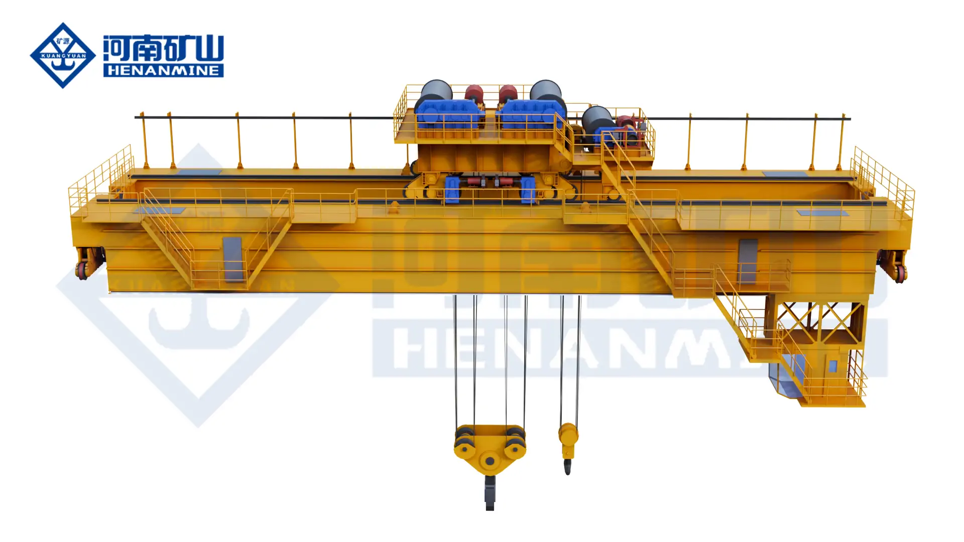
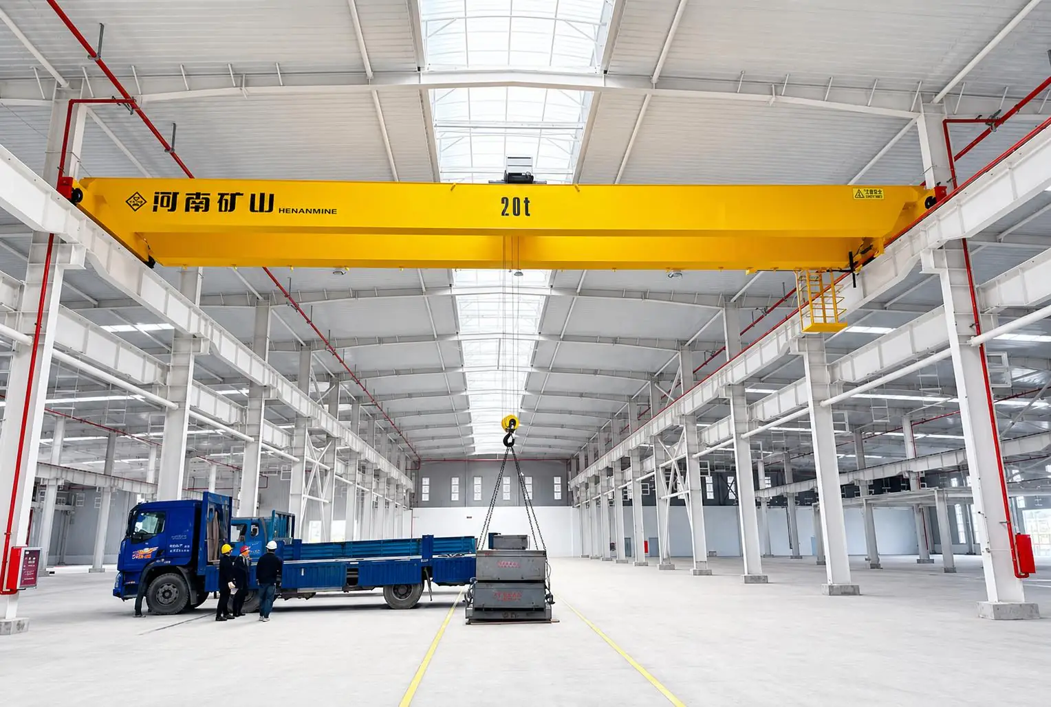
    Move heated workpieces through a defined quenching sequence with a process crane. Immersion, withdrawal, lifting geometry and thermal exposure determine the mechanism and controls.

    Lifting capacity5t – 80t
    Span7.5m – 35m
    Working classA7 – A8
    Technical specifications

    Define the total suspended load, duty and site conditions for your project.

    Technical specifications

    Check the load.
    Plan the configuration.

    Parameters and equipment options are matched to the application and confirmed in the technical proposal.

    Discuss your configuration
    Capacity5t – 80t
    Span7.5m – 35m
    Lifting height4m – 20m
    Working classA7 – A8
    Hoisting speed8m/min – 20m/min
    Trolley travel8m/min – 25m/min
    Crane travel10m/min – 30m/min
    Power supply380V/50Hz; 220V-660V/50Hz/60Hz
    ControlsManual control / PLC automatic control

    Final parameters, dimensions, wheel loads and supply scope follow the approved project specification.

    Application & operation

    Matched to the handling task.

    Heat-treatment lines

    Coordinate movement between heating, transfer and quenching positions.

    Large heated workpieces

    Match lifting fixtures and clearances to the component and tank geometry.

    Selection considerations

    Start with your operating conditions.

    01

    Load & lifting arrangement

    Specify heated workpiece, lifting fixture and load geometry. Include lifting-appliance weight and the required lifting positions.

    02

    Site & available space

    Provide tank depth, handling positions and available clearances. Coordinate the installation interfaces with the available site drawings.

    03

    Duty & control sequence

    Define immersion or withdrawal sequence, required speeds and thermal exposure. Identify the required movements and control interfaces in the enquiry.

    Configuration comparison

    Compare related lifting arrangements.

    Crane arrangementHandling configuration
    Quenching CraneMove heated workpieces through a defined quenching sequence with a process crane. Immersion, withdrawal, lifting geometry and thermal exposure determine the mechanism and controls.
    Metallurgical Bridge CraneLift hot process loads with a YZD metallurgical bridge arrangement selected for the complete load and thermal conditions. Specify the lifting appliance, duty cycle and operating-protection requirements.
    Double Girder Casting CraneLift and transfer molten-metal ladles with a YZ casting crane configured for the full suspended load and casting process. Review ladle interfaces, thermal exposure and the operating sequence together.
    YX Metallurgical Bridge CraneLift and turn material boxes with a YX metallurgical crane arrangement. The box interface, centre of gravity, turnover sequence and thermal conditions determine the lifting system.

    Operating protection & lifecycle support

    Plan beyond the equipment.

    01

    Operating protection

    Confirm overload protection, travel limits, brakes, emergency controls and the required process interlocks for the declared lifting task.

    02

    Installation & commissioning

    Agree runway reactions, structural interfaces, electrical connections, assembly, inspection and commissioning responsibilities before delivery.

    03

    Inspection & spares

    Plan inspection and maintenance of hoisting mechanisms, lifting fixtures and heat-exposed components. Agree service access, documentation and the required spare-parts scope.

    Questions before the order

    Clarify the details
    that shape the crane.

    What information is needed for a quenching crane quotation?+

    Provide heated workpiece, lifting fixture and load geometry; tank depth, handling positions and available clearances; and immersion or withdrawal sequence, required speeds and thermal exposure. Include drawings and the project destination when available.

    Which process data affects the lifting mechanism?+

    Provide the complete movement sequence, immersion and withdrawal requirements, workpiece condition and fixture details. The required motion characteristics and protection are specified for that process.

    What installation and support scope should be agreed?+

    Agree runway reactions, structural interfaces, electrical connections, assembly, inspection and commissioning responsibilities before delivery. Specify the documentation, training and spare-parts support needed for the project.

    Related equipment

    Explore the alternatives.
    Let’s discuss your project

    The right crane starts
    with your lifting task.

    Share heated workpiece, lifting fixture and load geometry, together with your site layout and operating cycle.
    info@hnksglobal.com
  • Heavy-Duty Double-Girder Overhead Cranes: Define Load and Duty Separately

    Heavy-Duty Double-Girder Overhead Cranes: Define Load and Duty Separately

    Selection guide

    Heavy-Duty Double-Girder Overhead Cranes: Define Load and Duty Separately

    A heavy-duty description needs an operating cycle as well as a maximum load. Provide the lifting frequency, load pattern and bay geometry so the proposed double-girder arrangement can be assessed against a clear duty brief.

    Henan Mine CraneSelection guide · Updated 2026Crane selection, project scope and operating requirements
    Double Girder Overhead Crane for Heavy-Duty Lifting
    Double Girder Overhead Crane for Heavy-Duty Lifting
    Project planning notes

    Key points for this crane project.

    1. What Is a Double Girder Overhead Crane?
    2. Double Girder Overhead Crane Configurations
    3. Selection Considerations
    Read the technical guide

    What Is a Double Girder Overhead Crane?

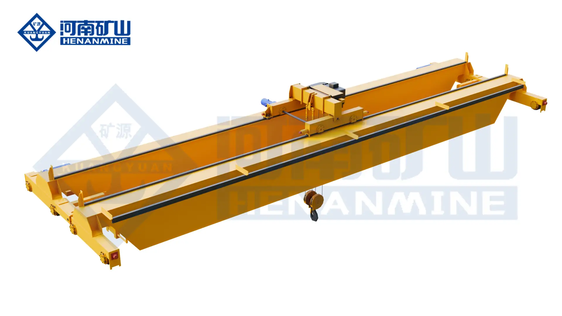
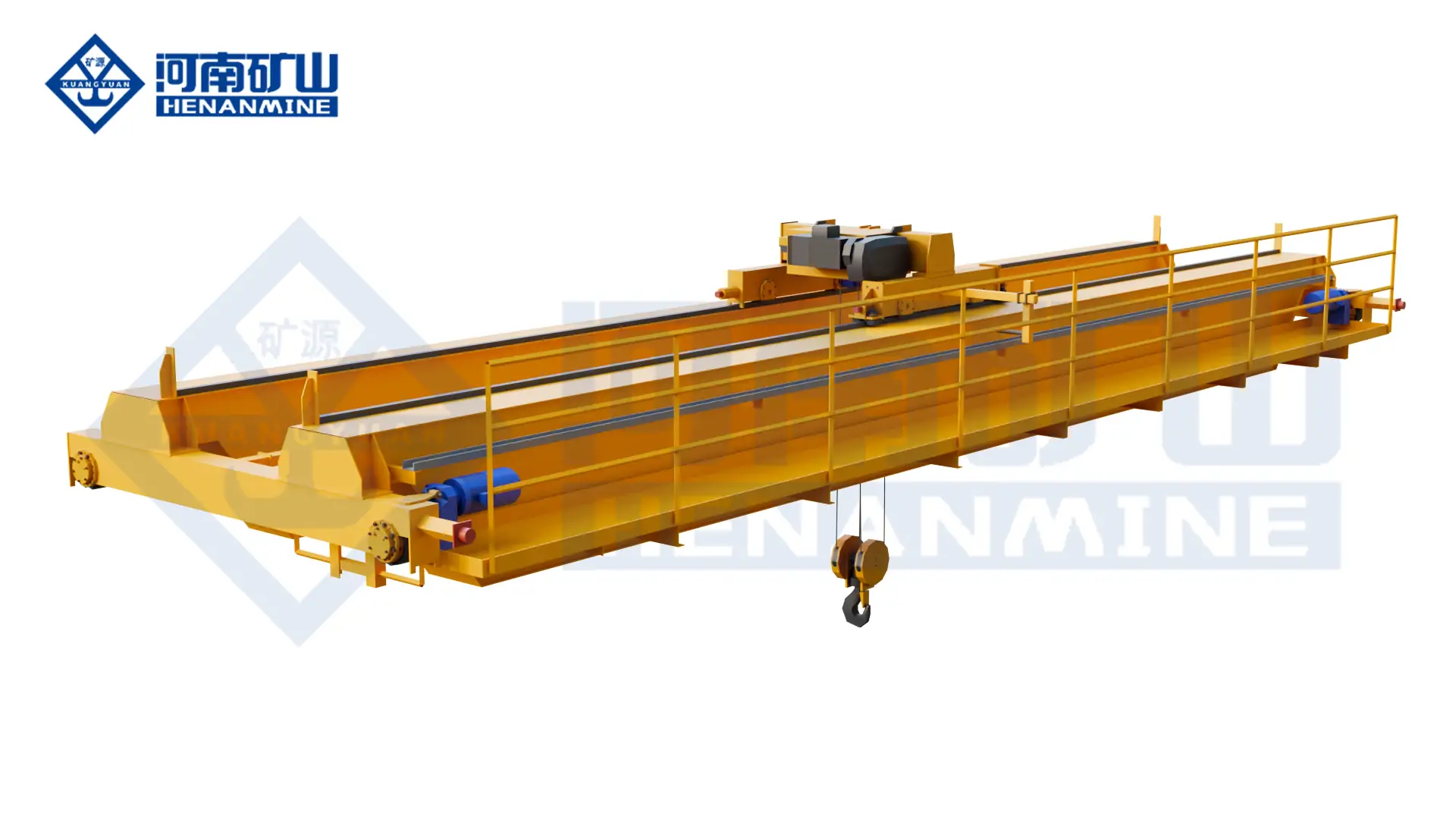
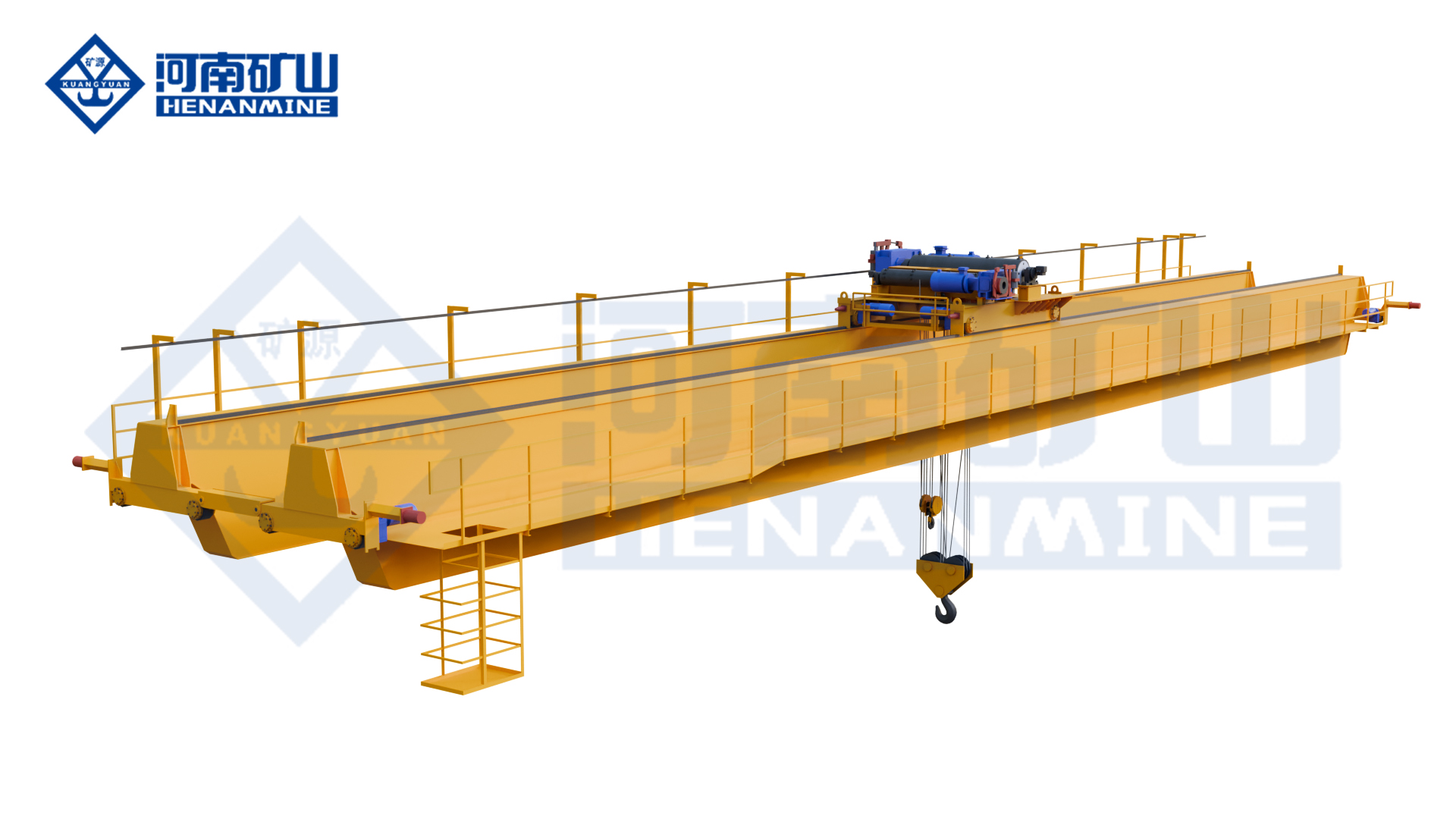
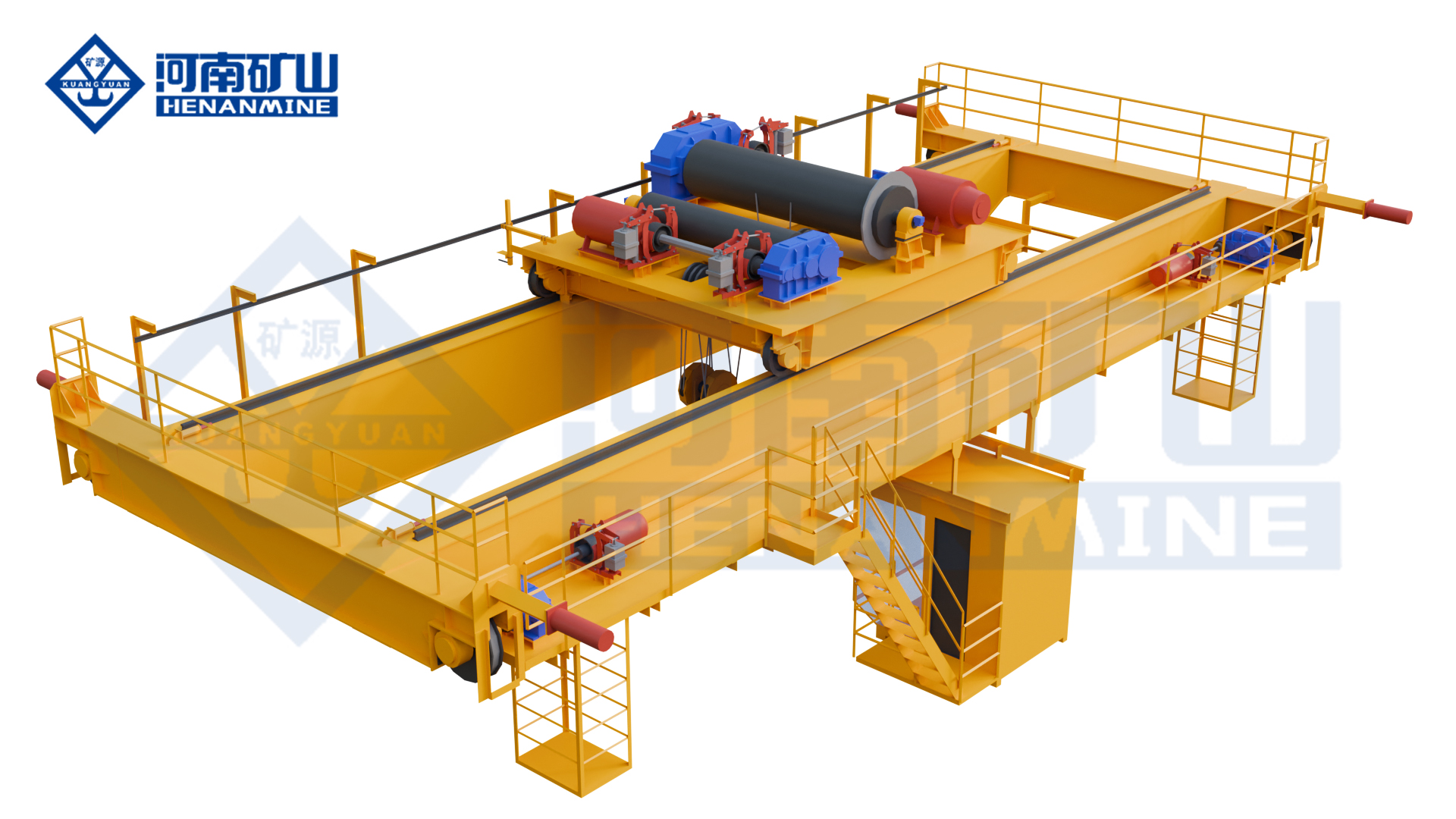
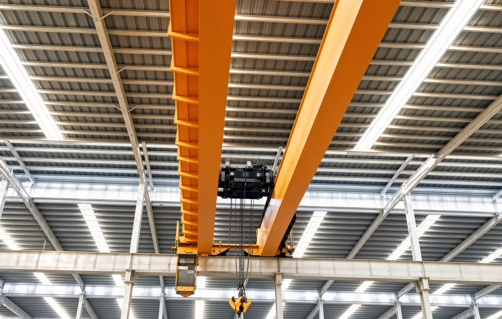
    A double girder overhead crane uses two parallel bridge girders carried by end trucks that travel along elevated runways. A trolley or electric hoist travels across the bridge, creating three powered motions: vertical lifting, cross travel and long travel. The same equipment family is also described as a double girder bridge crane, double girder EOT crane or double girder overhead travelling crane.

    The two-girder structure provides a stable platform for higher loads, longer spans, demanding operating cycles and larger trolley mechanisms. A top-running trolley can move above or between the girders, which often improves the highest hook position compared with an underslung hoist arrangement. Walkways, maintenance platforms, operator cabins, service hoists and process equipment can also be integrated when the approved design requires them.

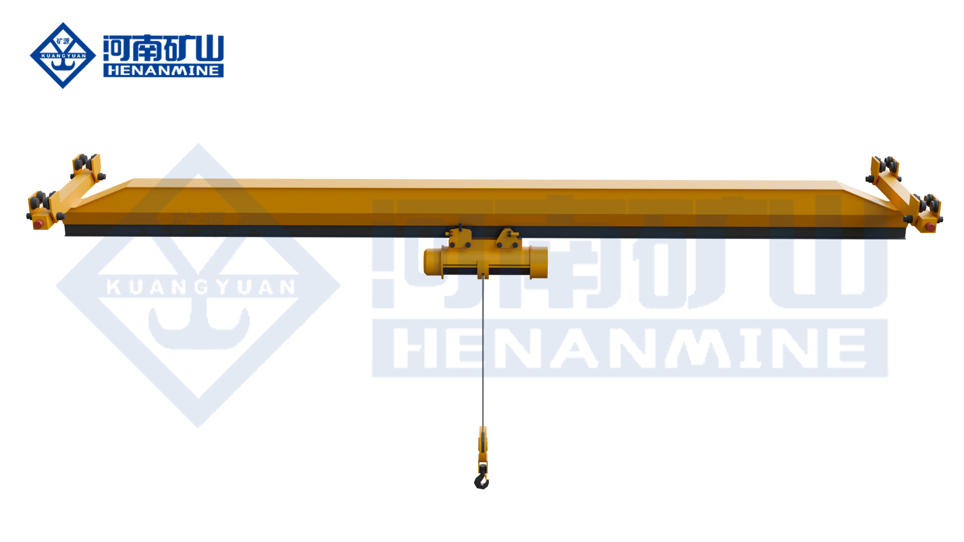
    Double girder construction is not automatically required at every capacity. A single-girder crane can remain more economical where load, span, duty and headroom are moderate. Double girder selection becomes commercially justified when the required capacity, bridge stiffness, lifting height, trolley arrangement, service access or process function cannot be achieved efficiently with a lighter configuration.

    The crane and its runway operate as one structural system. Bridge self-weight, trolley position, lifted load, acceleration, braking, skewing and impact generate vertical, lateral and longitudinal forces. Final wheel loads and support reactions must be coordinated with runway beams, columns, brackets and foundations before fabrication.

    Double Girder Overhead Crane Configurations

    01 · Electric-Hoist Double Girder Crane

    A compact electric wire-rope hoist travels on a trolley arrangement supported by two girders. The configuration suits general industrial handling where moderate capacity, controlled cost and relatively simple maintenance have priority.

    02 · Open-Winch Double Girder Crane

    A purpose-designed trolley carries separate drum, motor, gearbox, brakes, sheaves and controls. This architecture supports higher capacity, longer lift, demanding duty, redundancy and process-specific reeving.

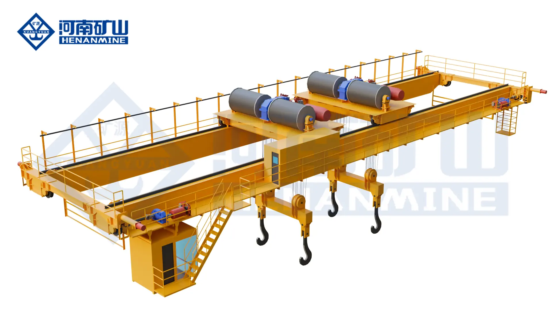
    03 · Double-Trolley Overhead Crane

    Two independently controlled trolleys provide separated lifting points for long loads, load turning, synchronized lifting or multiple production tasks. The control philosophy defines independent, coordinated and restricted operating modes.

    04 · Low-Headroom Double Girder Crane

    An optimized trolley and bridge arrangement maximizes upper hook elevation where roof clearance is limited. Girder depth, trolley envelope, walkway access and runway level require coordinated review.

    05 · Process Double Girder Crane

    Grab, magnet, clamp, rotating beam, C-hook, ladle beam or other attachments convert the crane into a process machine. Structure, mechanisms, controls and safety provisions are selected around the handled material.

    06 · Automated Double Girder Crane

    Position feedback, PLC control, anti-sway, collision management and plant interfaces support repeatable semi-automatic or unmanned cycles. Manual recovery and maintenance modes remain part of the control design.

    A packaged electric hoist and an open-winch trolley are not interchangeable price alternatives. The open-winch platform is selected when reeving, braking, duty, redundancy, speed range, maintenance access or process risk exceeds the capability of a standard packaged hoist.

    A project configuration should identify the trolley type, number of hooks, reeving, working class, motion speeds, control mode and service access before commercial comparison.

    Selection Considerations

    A reliable specification starts with the lifting process and building section, not with a catalogue model. The following inputs establish the technical and commercial basis for a double girder overhead crane proposal.

    Record maximum payload, normal payload, lifting beam, hook block, slings, clamps, magnets and every component carried below the trolley. Rated capacity follows the maximum approved suspended load.

    State runway rail-center span, bay travel length, pickup and placement zones, side approach, end approach and any maintenance or transfer areas.

    Define lowest pickup level, highest hook position, rail elevation, roof obstruction, load height, rigging depth and any extraction distance above machinery.

    Provide lifts per hour, shifts, annual operating hours, travel distances, average load and frequency of lifts near rated capacity. Working class follows actual service.

    Confirm rail type, runway beams, column spacing, brackets, foundations, allowable reactions and existing structural information. Crane capacity alone cannot validate the runway.

    Specify lifting, trolley and bridge speeds, low-speed range, stopping behavior, positioning tolerance, variable-frequency control and anti-sway requirements.

    Identify hook, grab, magnet, clamp, rotating beam, ladle beam or another attachment together with load dimensions, center of gravity and pickup method.

    Define temperature, dust, corrosion, hazardous classification, indoor or outdoor service, governing requirements, inspection authority and commissioning boundary.

    Commercial control: rated capacity, span and lift are insufficient without working class, runway data, trolley architecture, attachment details and a written supply boundary.

    Double Girder Compared with Other Overhead Crane Configurations

    ConfigurationStructural ArrangementTypical DutyCapacity Position
    Double girder with electric hoistTwo bridge girders; packaged wire-rope hoistGeneral industrial loads requiring stronger bridge stiffness or improved hook heightModerate to high within the approved hoist range
    Double girder with open-winch trolleyTwo girders; purpose-designed trolley and reevingHeavy loads, long lift, high duty and process handlingHigh to very high project-specific capacity
    Single girder overhead craneOne bridge girder; normally underslung hoistRoutine workshop, assembly, maintenance and warehouse handlingLight to moderate project range
    Double-trolley overhead craneTwo trolley or hoist units on one bridgeLong loads, rotation, synchronized lifting and separated pick pointsProject-specific combined and individual loads
    Underhung double girder craneBridge suspended below multiple runway supportsLarge clear-floor buildings, hangars and special assembly areasProject-specific
    Double girder gantry craneTwo girders carried by legs running on ground railsOutdoor yards or facilities without an elevated runway structureModerate to very high project range

    Technical Specification Framework

    The published general electric-hoist family provides a preliminary selection envelope. The approved technical proposal controls final values, and open-winch or special-purpose cranes are engineered beyond the standard family when required.

    ParameterEngineering BasisQuotation Requirement
    Rated capacityGross suspended load including all below-hook equipmentState main and auxiliary hook capacities separately
    SpanRunway rail centerline to centerlineConfirm actual building bay and end approaches
    Lifting heightLowest pickup to highest required hook elevationInclude load and rigging depth
    Working classLoad spectrum, starts, travel and annual serviceMechanism classes may differ from whole-crane class
    Hoisting mechanismCapacity, duty, lift, speed, redundancy and environmentDefine main, auxiliary and maintenance hooks
    Control modeVisibility, travel distance, process risk and site practiceMultiple modes require authority and transfer logic
    Power supplyCountry grid, voltage tolerance, frequency and earthingTransformer or conversion scope stated in the quotation
    Runway interfaceWheel loads, rail, beam, columns, brackets and foundationsRunway scope and structural approval separated commercially

    Special cranes for molten metal, hazardous areas, magnetic loads, bulk handling or automated production require a dedicated parameter sheet. General product-family values must not be transferred to a process crane without review.

    Hoisting, Travel and Control System

    Mechanism architecture determines operating performance, maintenance workload and lifecycle risk. Every motion should be selected from the declared load spectrum and production cycle.

    Hoist or Open-Winch Trolley

    Packaged hoists control cost and simplify general service. Open-winch trolleys provide configurable drums, reeving, brakes, speeds and redundancy for heavy or high-duty operation.

    Main and Auxiliary Hoists

    An auxiliary hook supports faster handling of lighter loads, maintenance work and load orientation. Combined-load restrictions and hook separation must be documented.

    Variable-Frequency Drives

    Controlled acceleration, deceleration and low-speed operation reduce load swing and mechanical shock. Drive settings follow motor, brake, gearbox and process requirements.

    Brakes and Holding Functions

    Service and holding brakes are selected around load consequence, duty and applicable requirements. Monitoring or redundant arrangements are added where the process demands them.

    Travel and Skew Control

    Matched end-carriage drives, wheel geometry, rail alignment and optional feedback control support stable bridge travel. Mechanical alignment remains essential even with electronic correction.

    Positioning and Anti-Sway

    Encoders, laser positioning, zone control and anti-sway functions support repeatable placement. Required accuracy and fallback behavior must be defined before control design.

    Operator Interface

    Pendant, radio and cabin controls are selected around visibility, travel distance, heat, dust and process risk. Alarms, indicators and authorization levels form part of the interface.

    Safety and Compliance

    Overload protection, limits, emergency stop, buffers, end stops, travel warning and electrical protection form the base system. Additional functions follow the hazard assessment and governing standard.

    Top-running multiple-girder cranes with top-running trolley hoists fall within the scope of ASME B30.2 where that standard governs the project. EN, ISO, FEM, national regulations or owner specifications may also apply.

    Applications and Working Conditions

    IndustryTypical LoadRecommended DirectionOperating Objective
    Heavy manufacturing and fabricationMachines, weldments, dies, fixtures and large assembliesElectric-hoist or open-winch double girder craneStable full-bay lifting and controlled positioning
    Steel mill and foundryLadles, slabs, coils, billets, rolls, scrap and maintenance equipmentProcess double girder crane with dedicated attachmentHigh duty, heat resistance and process-specific safety
    Power and energy equipmentGenerators, turbines, transformers, nacelles and hubsOpen-winch or double-trolley double girder craneHeavy component assembly and maintenance with precise movement
    Paper and process plantRolls, drums, motors, pumps and production equipmentElectric-hoist or multi-trolley double girder craneWide coverage in humid, dusty or corrosive service
    Bulk material handlingOre, coal, biomass, waste, clinker and slagGrab double girder craneRepeated loading, unloading and stockpile transfer
    Warehouse and automated storageCoils, dies, long products, pallets and production stockAutomated or semi-automated double girder craneRepeatable inventory movement and integration with plant controls

    Hazardous areas, molten metal, outdoor exposure, high temperature, coastal corrosion, clean production and seismic conditions require project-specific engineering. A standard workshop crane should not be reclassified by changing only the motor enclosure or surface coating.

    Project Case: 43-Crane Offshore Wind Manufacturing Program

    A large offshore wind manufacturing program required coordinated handling of nacelles, hubs, blades and related components. The first phase included 43 double girder cranes installed and placed into operation. The equipment program combined high-capacity lifting, multiple hooks, controlled low-speed motion and lifecycle monitoring.

    Automatic speed adjustment matched travel behavior to load condition.

    The engineering value lies in system coordination rather than capacity alone. Load geometry, lifting points, trolley separation, bridge stiffness, synchronized motion, runway reactions, operator visibility and process interlocks were treated as one handling system. The case demonstrates the scalability of double girder architecture from standard electric-hoist cranes to major engineered lifting equipment.

    Engineering, Manufacturing and Quality Documentation

    A double girder overhead crane package should connect approved design inputs to structural fabrication, mechanism selection, electrical integration, inspection and final acceptance. Documentation requirements should be agreed before manufacturing release.

    Design Package

    General arrangement, hook approaches, wheel loads, runway reactions, deflection basis, mechanism duty, electrical demand and control narrative.

    Structural Records

    Material identification, welding procedures, welder qualifications, dimensional reports and specified nondestructive examination.

    Mechanism Data

    Drum, rope, sheave, hook, motor, gearbox, brake, wheel, bearing and lubrication data matched to the declared duty.

    Electrical Documents

    Single-line diagram, schematics, drive settings, protection coordination, conductor details and interface schedule.

    Inspection and Tests

    Inspection plan, witness points, dimensions, brakes, limits, alarms, interlocks, no-load testing and contracted load testing.

    Handover Package

    Final drawings, certificates, test records, manuals, spare-parts list, maintenance schedule and configured parameters.

    Installation, Commissioning and Lifecycle Planning

    Runway Survey

    Verify rail span, elevation, straightness, joint condition, end stops, buffers, conductor route and structural information before final bridge release.

    Delivery and Assembly Plan

    Define shipping splits, unloading equipment, assembly area, mobile-crane access, roof clearance, work-at-height controls and production shutdown.

    Bridge and Trolley Installation

    Assemble girders and end trucks to approved tolerances, install the trolley, align drives and confirm clearances before powered travel.

    Electrification and Controls

    Install conductors, festoons, isolators, grounding, pendant or radio stations, cabin equipment, sensors and plant interfaces.

    Functional Commissioning

    Verify motor direction, drives, brakes, upper and lower limits, travel limits, buffers, alarms, emergency stop and interlocks without load.

    Load and Site Acceptance

    Complete required proof, rated-load and operational tests under an approved procedure with calibrated instruments and documented results.

    Operator and Maintenance Handover

    Transfer operating limits, inspection points, lubrication schedule, troubleshooting logic, spare parts and emergency procedures.

    Lifecycle Service Plan

    Base inspection and maintenance intervals on actual duty, environment and load history rather than calendar time alone.

    Double Girder Overhead Crane Price and Project Cost

    Double girder overhead crane price depends on capacity, span, lifting height, working class, trolley type, motion speeds, control system, runway scope, installation country and acceptance requirements. Current North American installed-market examples provide budget context only and are not fixed Henan Mine Crane prices.

    Budget ItemIndicative Market PositionTypical ScopeMain Cost Drivers
    General electric-hoist double girder craneProject quotationBridge, end trucks, hoist trolley, electrification and documentsCapacity, span, lift, duty, headroom, voltage and destination
    Open-winch heavy-duty double girder craneProject quotationEngineered trolley, reeving, brakes, access platforms and controlsLoad spectrum, mechanisms, redundancy, speeds and process risk
    Runway and support structureSeparate project itemRails, runway beams, brackets, columns, bracing and foundationsWheel loads, travel length, column spacing and building capacity
    International delivery and site servicesSeparate project itemPacking, freight, erection, commissioning, load test and trainingShipping dimensions, destination, local labor, access and test weights

    Price normalization: compare bridge structure, trolley, hoisting mechanism, runway steel, electrification, controls, documentation, packing, freight, erection, commissioning, load testing, training, spare parts and exclusions as separate line items.

    Information Required for a Double Girder Overhead Crane Quote

    A technically comparable quotation requires operating, load, building and commercial information together. Dimensioned plans, runway drawings, load sketches and site photographs should accompany the following data.

    Load Data

    Maximum and normal mass, dimensions, center of gravity, lifting points, rigging, attachment weight and any future load allowance.

    Crane Geometry

    Runway rail-center span, travel length, rail elevation, required lift, hook approaches, building section and overhead obstructions.

    Duty and Throughput

    Lifts per hour, shifts, annual hours, load spectrum, full-load frequency, travel distance and production consequence.

    Runway and Building

    Rail profile, runway beams, column spacing, brackets, allowable reactions, foundation data and existing structural condition.

    Hoisting Arrangement

    Electric hoist or open winch, main and auxiliary hooks, trolley quantity, reeving, lifting speeds and synchronization requirement.

    Controls and Safety

    Pendant, radio or cabin operation, variable-frequency drives, positioning, anti-sway, collision control and required monitoring.

    Environment and Power

    Voltage, frequency, phase, ambient temperature, dust, humidity, corrosion, hazardous area and indoor or outdoor exposure.

    Delivery Boundary

    Destination, trade term, runway scope, installation, inspection, testing, training, spare parts, documentation language and schedule.

    Double Girder Overhead Crane FAQ

    When is a double girder overhead crane preferred?

    Double girder construction is normally considered for higher capacities, longer spans, demanding duty, improved hook height, open-winch trolleys, multiple hooks, walkways or process-specific attachments.

    Is a double girder crane always more expensive than a single girder crane?

    The bridge normally has greater structural weight and more complex trolley arrangements. Total project value depends on whether the double girder design avoids building changes, improves hook height or supports duty that a single girder crane cannot provide.

    What is the difference between an electric-hoist and open-winch double girder crane?

    An electric hoist is a packaged lifting unit suited to defined general-duty ranges. An open-winch trolley separates drum, motor, gearbox, brakes and reeving for higher capacity, heavier duty, redundancy or process customization.

    Can a double girder overhead crane have two trolleys?

    Two trolleys can operate independently or in coordinated modes for long loads, rotation and multiple pick points. Combined capacity, load sharing, trolley collision limits and control authority require definition.

    Does double girder construction improve lifting height?

    A top-running trolley can travel above or between the girders and often places the hook closer to roof level. Actual hook height depends on rail elevation, girder depth, trolley envelope, hook block and maintenance clearance.

    What working class is required?

    Working class follows the load spectrum, lifts per hour, travel, shifts and annual service. The published general electric-hoist family covers A3–A6; process or high-duty cranes require separate mechanism and crane classification.

    Can an existing runway support a new double girder crane?

    Only after structural verification. The assessment should use actual crane self-weight, wheel loads, trolley position, lifted load, impact, lateral forces, rail condition and support capacity.

    How much does a double girder overhead crane cost?

    International projects require quotations based on complete equipment and site scope.

    Which information has the greatest effect on price?

    Capacity, span, lift, duty, trolley architecture, speed, runway length, controls, environment, structural work, freight, installation access and testing boundary create the largest cost differences.

    What should a final quotation include?

    The quotation should identify parameters, working class, mechanisms, runway reactions, control system, safety devices, documents, tests, packing, freight, installation, commissioning, training, spare parts, schedule and exclusions.

    Related Overhead Crane Products

    Compare alternative bridge structures and process configurations after capacity, span, hook height, duty, load geometry, runway and operating environment have been defined.

    Single-Girder Overhead Crane

    Lower-self-weight bridge configuration for general workshops, warehouses, assembly areas and maintenance bays.

    Multi-Support Double-Girder Underhung Crane

    Large-span suspended system for aircraft hangars, assembly buildings and facilities requiring clear production floors.

    Double-Girder Casting Crane

    Heavy-duty metallurgical configuration engineered for molten-metal handling, high temperature and severe service.

    Electromagnetic Bridge Crane

    Magnetic handling system for plates, billets, profiles and scrap with project-specific power continuity and controls.

    Three-Trolley Electric Hoist Bridge Crane

    Multi-trolley arrangement for long workpieces, production handling and maintenance tasks requiring several pick points.

    Submit the load list, capacity, span, lifting height, runway drawings, operating duty, trolley requirement, motion speeds, control mode, power supply, environment, installation boundary and destination. Henan Mine Crane will prepare a coordinated technical configuration and commercial quotation.

    Discuss the crane arrangement for your project.

    A heavy-duty description needs an operating cycle as well as a maximum load. Provide the lifting frequency, load pattern and bay geometry so the proposed double-girder arrangement can be assessed against a clear duty brief. Share the load, available drawings, working cycle and site conditions with Henan Mine Crane so the required configuration and supply boundary can be discussed.

    Related crane configurations

    LH Electric Hoist Double Girder Crane

    View product parameters
    Lifting capacity: 3, 5, 10, 16, 20 tSpan: 10.5–31.5 mLifting height: 6, 9, 12 or 18 m

    Use an LH double-girder bridge with an electric-hoist trolley for workshop lifting, assembly and maintenance. Match the hoist arrangement to the suspended load, hook travel and available building space.

    Double Girder Casting Crane

    View product parameters
    Lifting capacity: 75/20–200/50 tSpan: 10m – 35mLifting height: 6m – 25m

    Lift and transfer molten-metal ladles with a YZ casting crane configured for the full suspended load and casting process. Review ladle interfaces, thermal exposure and the operating sequence together.

    Updated 2026 · Henan Mine Crane

  • Portal Harbor Crane

    Portal Harbor Crane

    Port Cranes / Henan Mine Crane

    Portal Harbor Crane

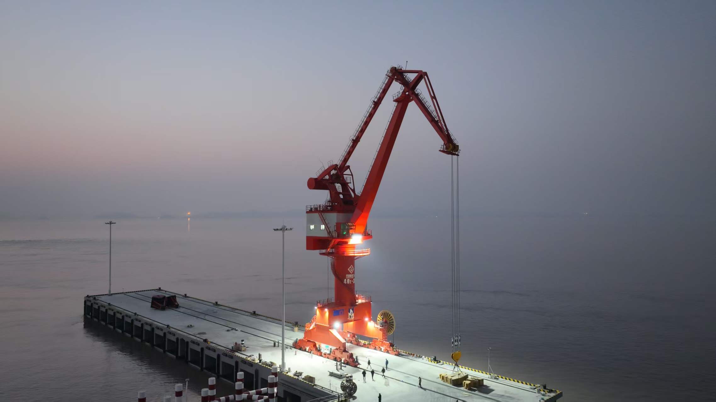
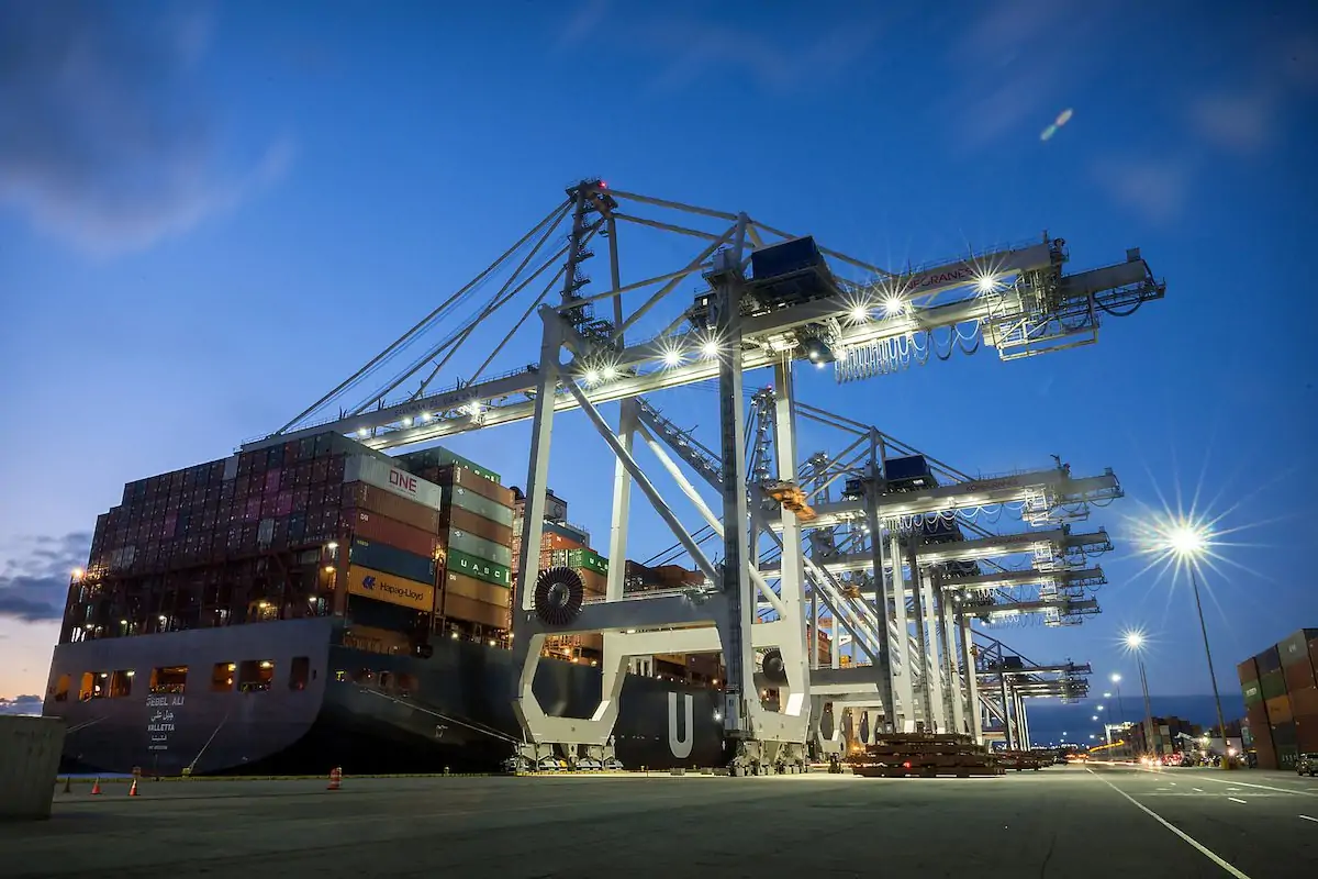
    Handle cargo with a portal harbor crane configured for the working radius and lifting appliance. Define hook or grab operation, quay interfaces, outreach and the operating cycle.

    Lifting capacity5t – 400t
    Working range10m – 50m
    Working classA7 – A8
    Technical specifications

    Define the total suspended load, duty and site conditions for your project.

    Technical specifications

    Check the load.
    Plan the configuration.

    Parameters and equipment options are matched to the application and confirmed in the technical proposal.

    Discuss your configuration
    Rated Lifting Capacity5t – 400t
    Lifting Height8m – 40m
    Luffing Range10m – 50m
    Lifting Speed0.5-6m/min
    Slewing Speed0.5-1.5r/min
    Travel Speed5-25m/min
    Working ClassA7 – A8
    Protection LevelIP55 (IP65 optional)
    Site operating conditionsDeclare climate, wind exposure and permitted operating limits for the proposed configuration

    Final parameters, dimensions, wheel loads and supply scope follow the approved project specification.

    Application & operation

    Matched to the handling task.

    Quay cargo handling

    Coordinate lifting coverage with vessel, quay and receiving positions.

    Bulk or unit loads

    Select the declared lifting appliance and handling sequence for each cargo type.

    Selection considerations

    Start with your operating conditions.

    01

    Load & lifting arrangement

    Specify cargo, lifting appliance and required load at working radius. Include lifting-appliance weight and the required lifting positions.

    02

    Site & available space

    Provide quay rail layout, outreach, backreach and vessel clearances. Coordinate the installation interfaces with the available site drawings.

    03

    Duty & control sequence

    Define handling cycle, site wind conditions and control arrangement. Identify the required movements and control interfaces in the enquiry.

    Configuration comparison

    Compare related lifting arrangements.

    Crane arrangementHandling configuration
    Portal Harbor CraneHandle cargo with a portal harbor crane configured for the working radius and lifting appliance. Define hook or grab operation, quay interfaces, outreach and the operating cycle.
    Ship-To-Shore Crane (STS)Transfer containers between ship and quay with an STS crane selected for the berth and vessel envelope. Define the lifting-appliance arrangement, outreach, rail position and handling cycle.
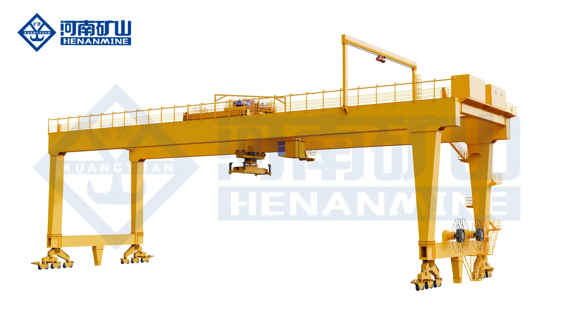
    Rail-Mounted Container Gantry CraneHandle containers along a fixed yard runway with a rail-mounted container gantry crane. Coordinate the spreader, stacking geometry, rail layout and transfer positions around the terminal operation.
    Rubber Tyred Gantry (RTG)Use a rubber-tyred gantry for heavy handling where the operating layout requires a mobile tyre-supported arrangement. Define the load, steering modes, route and ground conditions for the project.

    Operating protection & lifecycle support

    Plan beyond the equipment.

    01

    Operating protection

    Define the permitted load cases, operating limits, travel protection and lifting-appliance interlocks for the declared cargo-handling modes.

    02

    Installation & commissioning

    Coordinate runway or pavement interfaces, operating clearances, power arrangements, assembly access and the terminal commissioning requirements.

    03

    Inspection & spares

    Plan inspection and maintenance of slewing and luffing mechanisms, rail travel and cargo-handling appliances. Agree service access, documentation and the required spare-parts scope.

    Questions before the order

    Clarify the details
    that shape the crane.

    What information is needed for a portal harbor crane quotation?+

    Provide cargo, lifting appliance and required load at working radius; quay rail layout, outreach, backreach and vessel clearances; and handling cycle, site wind conditions and control arrangement. Include drawings and the project destination when available.

    Why is a load-radius requirement needed?+

    The required load must be related to the working radius and lifting appliance. Provide vessel and quay geometry, cargo weights and each intended operating mode.

    What installation and support scope should be agreed?+

    Coordinate runway or pavement interfaces, operating clearances, power arrangements, assembly access and the terminal commissioning requirements. Specify the documentation, training and spare-parts support needed for the project.

    Related equipment

    Explore the alternatives.

    Let’s discuss your project

    The right crane starts
    with your lifting task.

    Share cargo, lifting appliance and required load at working radius, together with your site layout and operating cycle.
    info@hnksglobal.com
  • Overhead Crane Manufacturer & Supplier

    Overhead Crane Manufacturer & Supplier

    Overhead Cranes / Henan Mine Crane

    Overhead Crane Manufacturer & Supplier

    Select an overhead crane around your lifting task, workshop and operating cycle. Compare bridge, underhung and specialist configurations with Henan Mine Crane before defining the supply scope.

    Lifting taskWorkshop & industrial
    Building interfaceProject-specific
    Operating dutySelected for the process
    Technical specifications

    Define the total suspended load, duty and site conditions for your project.

    Technical specifications

    Check the load.
    Plan the configuration.

    Parameters and equipment options are matched to the application and confirmed in the technical proposal.

    Discuss your configuration
    Single GirderLower structural weight and compact arrangement
    Double GirderGreater rigidity and more room for hoist or trolley systems
    UnderhungPreserves floor space and can follow suspended runway layouts
    Explosion-ProofEquipment configuration matched to a defined hazardous area
    MetallurgicalSafety and thermal design for hot, high-duty material handling
    GrabPurpose-built bulk material pickup and discharge
    ElectromagneticReduces manual rigging for magnetic steel products

    Final parameters, dimensions, wheel loads and supply scope follow the approved project specification.

    Application & operation

    Matched to the handling task.

    General workshop lifting

    Review load, hook coverage and daily operating requirements.

    Special industrial processes

    Define any metallurgical, hazardous-area, magnetic or bulk-handling requirements separately.

    Selection considerations

    Start with your operating conditions.

    01

    Load & lifting arrangement

    Specify material, lifting attachment and complete suspended load. Include lifting-appliance weight and the required lifting positions.

    02

    Site & available space

    Provide workshop plan, runway geometry and available headroom. Coordinate the installation interfaces with the available site drawings.

    03

    Duty & control sequence

    Define operating duty, process conditions and required supply scope. Identify the required movements and control interfaces in the enquiry.

    Configuration comparison

    Compare related lifting arrangements.

    Crane arrangementHandling configuration
    Overhead Crane Manufacturer & SupplierSelect an overhead crane around your lifting task, workshop and operating cycle. Compare bridge, underhung and specialist configurations with Henan Mine Crane before defining the supply scope.
    Single-Girder Bridge CraneUse an LDA single-girder bridge and electric hoist for general workshop material handling. Select the lifting capacity, runway geometry and hoist duty around the building and load.
    LH Electric Hoist Double Girder CraneUse an LH double-girder bridge with an electric-hoist trolley for workshop lifting, assembly and maintenance. Match the hoist arrangement to the suspended load, hook travel and available building space.
    Single-Beam Suspension CraneSuspend an LX single-girder crane from an approved overhead runway to cover workshop lifting positions. Building support, runway geometry and available hook height determine the installation.

    Operating protection & lifecycle support

    Plan beyond the equipment.

    01

    Operating protection

    Confirm overload protection, travel limits, brakes, emergency controls and the required process interlocks for the declared lifting task.

    02

    Installation & commissioning

    Agree runway reactions, structural interfaces, electrical connections, assembly, inspection and commissioning responsibilities before delivery.

    03

    Inspection & spares

    Plan inspection and maintenance of selected lifting mechanism, runway interfaces and service access. Agree service access, documentation and the required spare-parts scope.

    Questions before the order

    Clarify the details
    that shape the crane.

    What information is needed for a overhead crane manufacturer & supplier quotation?+

    Provide material, lifting attachment and complete suspended load; workshop plan, runway geometry and available headroom; and operating duty, process conditions and required supply scope. Include drawings and the project destination when available.

    How can I compare proposals from different crane suppliers?+

    Issue the same load, building and duty information, then compare the technical configuration and supply scope. Clarify runway, electrical, installation, commissioning and documentation responsibilities.

    What installation and support scope should be agreed?+

    Agree runway reactions, structural interfaces, electrical connections, assembly, inspection and commissioning responsibilities before delivery. Specify the documentation, training and spare-parts support needed for the project.

    Related equipment

    Explore the alternatives.

    Let’s discuss your project

    The right crane starts
    with your lifting task.

    Share material, lifting attachment and complete suspended load, together with your site layout and operating cycle.
    info@hnksglobal.com
  • Dam Gantry Cranes for Gates and Stoplogs: Load and Working-Path Inputs

    Dam Gantry Cranes for Gates and Stoplogs: Load and Working-Path Inputs

    Selection guide

    Dam Gantry Cranes for Gates and Stoplogs: Load and Working-Path Inputs

    Gate and stoplog handling needs the lifting appliance and operating positions defined by the project. Provide the load arrangement, required movements and civil interfaces so the gantry crane can be reviewed for the site.

    Henan Mine CraneSelection guide · Updated 2026Crane selection, project scope and operating requirements
    Henan Mine Crane overhead crane inside a workshop bay
    Henan Mine Crane overhead crane inside a workshop bay
    Project planning notes

    Key points for this crane project.

    1. A Gate-Handling Solution for Your Dam
    2. What Henan Mine Crane Can Provide
    3. QM Dam Gantry Crane Equipment Package
    Read the technical guide

    A Gate-Handling Solution for Your Dam

    A dam gantry crane, also called a dam-top or dam-crest gantry crane, travels along rails to connect gate slots with deck transfer, storage and maintenance positions. It handles the movement that a fixed gate hoist cannot provide between those locations.

    Our QM product family is configured around the gate and the site. The resulting package combines lifting duty, reach, connection geometry and outdoor protection, with a clear boundary between crane supply and site works.

    What Henan Mine Crane Can Provide

    A project-specific crane arrangement

    We develop the crane layout around the working positions: gate pickup, transfer, maintenance and parking. The arrangement makes the proposed lifting reach and clearances visible before manufacture.

    A coordinated equipment package

    The supply package can include the gantry, hoisting mechanisms, gate-handling beam, travel system and controls. Included equipment and optional functions are listed together in the technical offer.

    Support through installation and operation

    Installation guidance, commissioning, training and spare-parts support can be included in the project scope. The commercial offer identifies the selected service package and responsibilities.

    Your project offer: a proposed configuration, technical schedule and itemized supply scope. Detailed approval drawings and handover documentation follow the agreed engineering and delivery stages.

    QM Dam Gantry Crane Equipment Package

    Equipment / parameterHow the package is configured
    Product familyQM hydraulic gate-hoist gantry crane for water-control equipment.
    Main hoisting systemRating based on suspended load and the approved gate operating-force cases; single or coordinated lifting positions as appropriate.
    Gate connectionBeam and attachment arrangement matched to gate lifting points and slot clearances.
    Gantry and runway coverageRail span, travel and lifting reach matched to gate bays, transfer route and parking position.
    Lifting strokeTravel above and below rail matched to pickup, transfer and maintenance elevations.
    Operating speeds and controlsMotion and positioning configuration matched to the handling sequence and duty.
    Auxiliary liftingA separate maintenance lifting arrangement where included in the project package.
    Outdoor serviceCoating, drainage, electrical protection and parking restraints selected for site exposure.

    Capacity, span, stroke, speeds and duty classification are project-specific. The technical schedule identifies the proposed values and their design basis; the approved drawings define the manufactured configuration.

    Equipment for Spillway, Intake and Tailrace Handling

    ApplicationCrane solutionPractical result
    Spillway stoplogsLifting arrangement and beam for individual elements, with access to the storage rack.Place and recover stoplogs through the maintenance sequence.
    Intake gatesGate-specific attachments, lifting stroke and controlled approach to the guides.Move the gate between its slot and the deck handling position.
    Tailrace / draft-tube gatesBelow-rail lifting coverage and transfer to the maintenance area.Support isolation-gate handling during generating-unit maintenance.
    Removable trash racksPanel lifting connection and deck transfer coverage.Remove rack sections for inspection or replacement.

    Gate-panel handling and debris cleaning are separate functions. A cleaning grab or rake belongs in the package only when that duty is included.

    Crane Configurations We Can Develop

    We translate the gate attachment geometry and handling route into a lifting arrangement. The configuration review connects each operating requirement with a mechanism, interface or control function.

    Project requirementProposed solutionEngineering output
    A central pickup or lifting beamA suitable single lifting position and gate connection.Attachment geometry, approach clearance and load basis.
    A gate lifted at two sidesCoordinated lifting arrangement for the approved two-point geometry.Point loads, alignment limits and synchronization concept.
    Pickup below the water surfaceGate-handling beam with a defined engagement and release arrangement.Beam interface and connection-verification method.
    Several bays on one runwayRail travel and working coverage across the selected positions.Coverage layout and operating sequence.
    Replacement of an existing craneA new arrangement evaluated against the existing runway and deck.Proposed wheel reactions and an interface review for civil verification.

    Emergency closure and movement under flow are developed as specific operating duties. Their mechanism, power-loss response and acceptance conditions are addressed separately from routine maintenance handling.

    Dam Gantry Crane Compared with Other Lifting Arrangements

    EquipmentWhat it providesApplication boundary
    QM dam gantry craneGate lifting and transfer between working positions along the runway.Combines gate interfaces, operating forces and crane travel.
    Fixed gate hoistDedicated gate operation at one location.Useful for immediate local operation or simultaneous operation of several gates.
    Double-Girder Gantry CraneOutdoor lifting of machinery and dry components.Gate operation under water loads requires a separate engineered configuration.
    Truss Gantry CraneOutdoor construction and component handling.General handling duty does not establish gate holding or emergency capability.
    Electric-Hoist Overhead CraneLifting within an indoor maintenance bay.Building runway coverage differs from dam-deck and submerged pickup access.

    A mobile crane serves gate bays in sequence. We evaluate the handling route and required availability when discussing whether one shared crane is appropriate.

    Engineering the Gate Load and Lifting Interface

    We use the approved gate-load schedule to develop the crane rating and lifting arrangement. The review covers the gate, suspended beam and gear, load distribution at the attachments and the applicable wet operating-force cases. Hydraulic force calculations remain part of the gate design.

    This illustrative calculation is not a crane rating: friction, buoyancy, hydraulic forces and the design criteria still affect the selection.

    The lifting-interface design connects the crane to the gate. Beam geometry, guide entry, connection confirmation and controlled release are addressed as one handling sequence, rather than left as unrelated accessories.

    Controls and Protection Matched to Gate Duty

    Positioning and alignment

    We develop the motion-control arrangement for gate placement and the selected lifting geometry. Two-point lifting includes an agreed synchronization concept and response to alignment faults.

    Holding and power loss

    The braking and holding arrangement follows the intended duty. Where emergency functions are included, the project design addresses the stated power-loss scenario and recovery sequence.

    Outdoor protection

    The package addresses humidity, water exposure and wind. Operating limits and storm-parking restraints are treated separately, with restraint reactions coordinated with the civil interface.

    These functions are identified in the technical offer and verified through the agreed test plan. Emergency gate movement under flow requires site-approved hydraulic and operating conditions.

    Crane Drawings That Connect with Your Civil Design

    Our crane design provides the equipment layout and interface information needed for coordination with the dam and runway. The project drawing package can include working positions, wheel reactions, rail geometry, parking restraints, electrification and service access.

    For a replacement, we compare the proposed crane arrangement with the available as-built information. The civil designer verifies the existing supports against the new reactions; the crane design then follows the agreed interface.

    Access to brakes, ropes and drives is considered alongside the gate transfer route. Component removal space and erection access are addressed during layout development, reducing the chance of discovering an obstruction after equipment arrives.

    Henan Mine Crane Hydropower Project Experience

    The project report describes factory assembly and lifecycle quality support.

    This is powerhouse lifting equipment. A dam gantry crane has its own operating forces and interfaces; the QM proposal addresses those separately. View the pumped-storage crane project

    Industry application: Big Bend Dam

    Knight Construction & Supply reports commissioning a 40-ton tailrace draft-tube crane at Big Bend Dam in 2021. The application demonstrates a dedicated tailrace handling role. Project contractor: Knight Construction & Supply.

    A Dam Gantry Crane Quote with a Clear Supply Boundary

    Our quotation separates the crane equipment from optional systems and site services. That gives your procurement team a defined package to budget and compare, with the delivery term, exclusions and service responsibilities stated in the offer.

    Quotation linePackage content
    Crane equipmentGantry, main hoisting arrangement, travel drives and service access.
    Gate-handling interfaceBeam, connecting hardware and the contracted engagement / release arrangement.
    Electrical and controlsOperating modes, positioning, protection and synchronization where included.
    Site interfacesRail and electrification supply, restraints and related installation scope as agreed.
    Delivery and site servicesPacking, transport, erection support, commissioning and training as selected.
    Operating supportDocumentation, selected spare parts and the agreed warranty and service terms.

    That broad advertisement does not define a matching configuration or installed cost. Your Henan Mine Crane offer is based on the selected equipment and project scope.

    A preliminary offer identifies the available design basis and open engineering items. The final equipment quotation follows the confirmed gate loads, arrangement and supply package.

    From Equipment Proposal to Handover

    Project stageOur contributionProject output
    Technical proposalDevelop the equipment configuration and identify the supply boundary.Proposed arrangement, technical schedule and commercial offer.
    Detailed engineeringDevelop the structural, mechanical and control arrangement for approval.Project drawings and interface information under the agreed documentation scope.
    Manufacture and inspectionProduce and inspect the equipment against the approved design.Manufacturing and test records required by the agreed inspection plan.
    DispatchPrepare identified components for the selected transport route.Packing information, component identification and shipment coordination.
    Installation and commissioningProvide the contracted site guidance or service package.Commissioning and acceptance records under the approved procedures.
    HandoverProvide the agreed operating documentation and training.Operation and maintenance information, parts identification and support contacts.

    The project schedule links drawing approval, manufacture, inspection, dispatch and site work. On-site attendance and installation responsibilities are defined in the offer; civil works and plant operating approvals remain with the appointed project parties.

    Support After the Crane Enters Service

    Henan Mine Crane offers technical support, maintenance guidance and replacement-parts assistance. We help identify parts from the crane model, nameplate, drawings and component details, and review equipment information for troubleshooting.

    For planned maintenance, the support scope can cover ropes, brakes, lifting connections, travel mechanisms and control functions. Warranty coverage, site attendance and spare-parts supply arrangements are set out in the commercial agreement.

    Start with the Information You Already Have

    A gate drawing, existing crane photo or brief project description is enough to start a technical discussion. Include the application, approximate load, project country and planned installation date where available. We help organize the remaining equipment-selection questions as the proposal develops.

    Request a Crane Proposal Contact Henan Mine Crane

    What happens next: we review the lifting task and site layout, discuss a suitable arrangement and define the equipment and service scope for quotation.

    Dam Gantry Crane FAQ

    What can Henan Mine Crane supply for a dam gantry project?

    A QM crane package can include the gantry, hoisting arrangement, gate connection, travel and controls, together with project engineering and selected site services. The quotation lists the included equipment and service responsibilities.

    Can you develop a solution from preliminary gate information?

    We can begin with available gate information and a site layout. The preliminary proposal identifies open items; approved loads and interfaces form the basis for final design.

    Can one crane serve several gates?

    We can evaluate a shared runway arrangement for multiple gate positions. Coverage, travel time and the required operating sequence determine whether the shared crane suits the plant.

    Can you provide synchronized two-point lifting?

    We can develop a coordinated lifting arrangement for the gate geometry and specified point loads. The technical offer defines the synchronization functions and alignment limits.

    Can you replace a crane on an existing dam runway?

    We can develop a replacement arrangement and provide its interface information. Reuse of the runway follows a survey and civil verification of the proposed reactions.

    Are emergency gate functions included?

    They are included only when part of the contracted engineering scope. The proposal addresses the specified water conditions, gate sequence, power-loss response and acceptance requirements.

    Do you provide installation and commissioning support?

    Support can be included in the project offer. The selected package identifies site guidance or attendance, commissioning work and the responsibilities of each party.

    What documentation accompanies the crane?

    The agreed handover package includes operating and maintenance information and the contracted drawings and test records. Documentation requirements are listed during technical and commercial review.

    Related Dam and Hydropower Lifting Equipment

    Electric-Hoist Overhead Crane

    Indoor service bays within the selected lifting rating.

    Dual-Trolley Overhead Crane

    Engineered lifting at two trolley positions in a building.

    Electric Hoist

    Local lifting of tools and smaller maintenance parts.

    600 t Pumped-Storage Crane

    A separate powerhouse lifting application for heavy generating equipment.

    Discuss the crane arrangement for your project.

    Work with Henan Mine Crane on the crane arrangement, gate-handling package and delivery scope for your dam project. Start with your available drawings or a brief description of the lifting task.

    Related crane configurations

    Explore crane product families and technical parameters ↗

    Updated 2026 · Henan Mine Crane

  • New Electric Hoist

    New Electric Hoist

    Electric Hoists / Henan Mine Crane

    New Electric Hoist

    Configure a compact electric hoist for a defined lifting point or crane system. Select the mounting arrangement, hook travel and operating duty around the load and installation space.

    Lifting capacity0.5t – 10t
    Lifting height3m – 30m
    DutyM5 – M6
    Technical specifications

    Define the total suspended load, duty and site conditions for your project.

    Technical specifications

    Check the load.
    Plan the configuration.

    Parameters and equipment options are matched to the application and confirmed in the technical proposal.

    Discuss your configuration
    Rated Lifting Capacity0.5t – 10t
    Lifting Height3m – 30m
    Lifting Speed0.3m/min – 8m/min
    Travel Speed10m/min – 20m/min
    Power Supply380V/50Hz, 415V/60Hz (Customizable)
    Motor Power0.5kW – 1.8kW
    Working ClassM5 – M6
    Protection LevelIP55 (IP65 optional)
    Working Environment-20℃ ~ 40℃, RH ≤ 85%

    Final parameters, dimensions, wheel loads and supply scope follow the approved project specification.

    Application & operation

    Matched to the handling task.

    Workshop lifting points

    Provide vertical lifting at a fixed or travelling installation.

    Crane mechanisms

    Integrate a matched electric hoist with the bridge and trolley arrangement.

    Selection considerations

    Start with your operating conditions.

    01

    Load & lifting arrangement

    Specify suspended load, hook travel and lifting speed requirement. Include lifting-appliance weight and the required lifting positions.

    02

    Site & available space

    Provide mounting method, beam details and available headroom. Coordinate the installation interfaces with the available site drawings.

    03

    Duty & control sequence

    Define load spectrum, starts per hour and site power. Identify the required movements and control interfaces in the enquiry.

    Configuration comparison

    Compare related lifting arrangements.

    Crane arrangementHandling configuration
    New Electric HoistConfigure a compact electric hoist for a defined lifting point or crane system. Select the mounting arrangement, hook travel and operating duty around the load and installation space.
    Modular Electric Hoist Overhead CraneUse a modular electric-hoist overhead crane for production, assembly and maintenance lifting. Select the hoist arrangement, hook coverage and movement control for the workshop and operating cycle.
    LH Electric Hoist Double Girder CraneUse an LH double-girder bridge with an electric-hoist trolley for workshop lifting, assembly and maintenance. Match the hoist arrangement to the suspended load, hook travel and available building space.
    Explosion-Proof Electric HoistSpecify an explosion-proof electric hoist for the declared load, mounting arrangement and hazardous area. Coordinate the hoisting mechanism, trolley, controls and electrical protection with the installation.

    Operating protection & lifecycle support

    Plan beyond the equipment.

    01

    Operating protection

    Specify the required load protection, hoisting limits, braking, emergency controls and any declared hazardous-area requirements.

    02

    Installation & commissioning

    Agree mounting or beam interfaces, trolley arrangement, electrical connections, inspection, testing and commissioning responsibilities.

    03

    Inspection & spares

    Plan inspection and maintenance of hoist rope or load-bearing element, hook assembly and travel unit. Agree service access, documentation and the required spare-parts scope.

    Questions before the order

    Clarify the details
    that shape the crane.

    What information is needed for a new electric hoist quotation?+

    Provide suspended load, hook travel and lifting speed requirement; mounting method, beam details and available headroom; and load spectrum, starts per hour and site power. Include drawings and the project destination when available.

    What is needed to select a fixed or travelling hoist?+

    State the mounting method and whether horizontal travel is required. Provide beam dimensions, available headroom, travel length, lifting load and the operating cycle.

    What installation and support scope should be agreed?+

    Agree mounting or beam interfaces, trolley arrangement, electrical connections, inspection, testing and commissioning responsibilities. Specify the documentation, training and spare-parts support needed for the project.

    Related equipment

    Explore the alternatives.

    Let’s discuss your project

    The right crane starts
    with your lifting task.

    Share suspended load, hook travel and lifting speed requirement, together with your site layout and operating cycle.

    info@hnksglobal.com
  • Biomass Handling Cranes: Fuel Characteristics and Feeding Requirements

    Biomass Handling Cranes: Fuel Characteristics and Feeding Requirements

    Selection guide

    Biomass Handling Cranes: Fuel Characteristics and Feeding Requirements

    Biomass material affects the grabbing and transfer arrangement used at the plant. Describe the fuel condition, storage area and feeding sequence so the attachment, crane duty and operating interfaces can be considered together.

    Henan Mine CraneSelection guide · Updated 2026Crane selection, project scope and operating requirements
    Henan Mine Crane overhead crane inside a workshop bay
    Henan Mine Crane overhead crane inside a workshop bay
    Project planning notes

    Key points for this crane project.

    1. Keep Fuel Moving from the Receiving Pit to the Boiler
    2. Biomass Crane Configuration and Technical Details
    3. Choose the Grab for the Fuel You Actually Handle
    Read the technical guide

    Keep Fuel Moving from the Receiving Pit to the Boiler

    A biomass crane transfers fuel in batches: it clears incoming deliveries, distributes material through the store, blends selected stocks and replenishes the feed hopper. The downstream feeder meters fuel to the boiler. We engineer the crane around both systems so reception work does not consume the capacity needed for feeding.

    One coordinated equipment package

    Bridge, trolley, hoisting system, fuel grab and controls are selected together. This keeps grab self-weight, usable payload, motion performance and electrical interfaces within one technical offer.

    Useful storage coverage

    We map pickup zones, hopper openings, approach distances and maintenance positions onto the fuel-store drawing. An overhead arrangement can reduce dependence on loader aisles inside the covered working area.

    A defined route to operation

    The offer can include installation guidance, commissioning, operating instruction and recommended spares. Equipment, site services and plant responsibilities are itemized for procurement.

    Biomass Crane Configuration and Technical Details

    ItemConfiguration supplied for the project
    Crane arrangementOverhead grab crane for a fuel hall or bunker; gantry arrangements evaluated for suitable outdoor storage.
    Lifting capacity and payloadThe technical schedule separates rated lifting load, grab self-weight and net fuel payload.
    Grab volume and closureSelected from fuel density range, particle size, moisture, required throughput and hopper dimensions.
    Span, travel and lifting heightDimensioned from runway centres, storage depth, discharge elevation and the usable working envelope.
    Motion speeds and dutyHoisting and travel speeds, acceleration and duty classification matched to the calculated load spectrum and cycles.
    Operating modesManual, assisted cycles or engineered automatic operation, with the included functions stated in the offer.
    Plant interfacesHopper demand, level signals, downstream readiness, restricted zones and agreed plant-network communications.

    The QZ catalogue capacity identifies the base product family. It does not establish fuel throughput or suitability for a particular continuous-duty cycle. Those values are set out for the offered crane.

    Choose the Grab for the Fuel You Actually Handle

    Fuel formHandling approachWhat our selection addresses
    Wood chipsA clamshell or other bulk-material grab matched to the chip characteristics.Bucket volume, penetration, retained load and discharge into the receiving hopper.
    Bark and fibrous residuesA grab evaluated for long pieces, interlocking material and incomplete closure.Tine or shell geometry, closing action and the risk of material hanging across the opening.
    Wood pellets and similar granular fuelsA bulk grab selected for retention and controlled discharge.Fines leakage, drop height, pellet damage and dust at transfer points.
    Loose agricultural residuesMaterial-specific grab selection using the actual size and compaction range.Low bulk density, uneven filling and the time needed to obtain a useful payload.
    Straw or biomass balesA separately engineered bale clamp or bale-handling attachment.Bale dimensions, mass, wrapping, gripping method and storage pattern.

    A single grab will not suit every fuel stream. For plants switching between fuels, we evaluate the density range, attachment changeover and controls needed for each operating mode.

    Select for the Whole Fuel-Handling Shift

    Our engineering review connects boiler demand with delivery peaks and storage movements. Low-density fuel can fill a large grab without producing much mass; a denser fuel can reach the permitted suspended load before the grab is full.

    Operating conditionHow we develop the arrangement
    Deliveries concentrated into a short daily windowCalculate receiving-pit clearance alongside ongoing hopper replenishment.
    Several fuel grades or storage zonesMap stock locations and blending transfers, with fuel segregation and task priorities included where required.
    A narrow hopper or restricted headroomMatch grab opening, approach height, travel path and discharge control to the available space.
    Automatic night-shift feedingDevelop task scheduling, hopper signals, sensing, alarms and a controlled recovery mode.
    Operation during crane maintenanceAssess buffer storage, recovery time, spare-grab arrangements and any alternative handling route.

    Biomass Crane Compared with Other Fuel-Handling Arrangements

    ArrangementWhere it fitsEffect on the plant layout
    Intelligent grab overhead craneA covered store needing multiple pickup zones, blending and automatic hopper replenishment.Travels above the store; runway structure, headroom and service access form part of the layout.
    Moving floor and conveyor systemA defined reclaim and transfer route with comparatively fixed material flow.Useful where continuous reclaim is the main task; blending and access depend on the storage design.
    Wheel loader with a receiving hopperSites needing mobile handling across accessible floor areas.Requires traffic routes, turning space and an operating plan for vehicles and people.
    Grab-and-hook gantry craneSuitable outdoor auxiliary handling or mixed bulk and equipment duties.Uses ground-supported runways and must suit the fuel, weather and operating frequency.
    Dedicated bale-handling craneStraw or other packaged biomass delivered as bales.Uses a bale-specific attachment and storage strategy instead of a loose-fuel bucket.

    We develop the crane and its transfer interfaces around the chosen fuel-handling system. A crane feeding a buffer hopper can work alongside conveyors and metering equipment.

    Size by Tonnes per Hour, Then Check the Suspended Load

    Net fuel payload depends on the grab’s useful volume, the fuel bulk density and how well it fills. Total handling demand includes receiving, blending and rehandling as well as boiler feed.

    Illustrative wood-chip calculation

    These are calculation inputs for this example, not specifications of an offered crane.

    What this means for selection: the lightest fuel may govern the volume and cycle rate, while the densest permitted fuel may govern lifting load. We check both and state the assumed routes, filling factor and productive time in the capacity calculation.

    Boiler thermal output alone is insufficient for crane sizing. Fuel consumption also depends on heating value, moisture and plant efficiency; the boiler supplier’s mass-flow requirement provides the feeding basis.

    Control the Sequence from Hopper Demand to Fuel Delivery

    For an automatic system, a hopper demand signal starts a handling task. The crane checks the permitted route and destination readiness, collects fuel from the assigned zone and discharges inside the programmed opening area.

    Receiving and feeding priorities

    The offered control sequence can prioritize hopper replenishment while allocating available cycles to truck reception, storage distribution and blending.

    Positioning and load control

    VFD motion control, position feedback, anti-sway and weighing can be included. Pile-surface sensing and slack-rope protection are specified where required by the selected grab and automation concept.

    Clear operating and recovery modes

    The control package identifies manual access, assisted cycles, automatic functions, alarms and recovery procedures. Multiple-crane coordination is engineered when included.

    The interface schedule defines signals exchanged with the plant PLC or DCS, their purpose and the response to a lost signal. The hopper and downstream feeder remain part of the coordinated process.

    Project Experience in Automated Fuel and Bulk Handling

    Biomass industry example: Kaunas, Lithuania

    Konecranes’ 2013 CXT Biomass brochure documents a New Heat project at a 10 MW boiler house in Kaunas. The fuel hall had three tipping bunkers, three storage areas and a double hopper.

    This was a Konecranes installation. It illustrates why cycle calculations, building clearance and the fuel-store layout matter alongside hoist capacity; its dimensions and ratings are not Henan Mine Crane product specifications.

    Henan Mine Crane: commissioned automatic grab technology

    Henan Mine Crane’s December 2025 project report records an automatic grab crane entering service at a waste incineration power generation facility. Its published functions include variable-frequency control, absolute-encoder feedback, anti-sway, fixed-point grabbing and constant-weight cyclic operation.

    This is experience in an adjacent fuel-handling application. A biomass proposal receives its own grab, material-flow and operating-duty selection.

    Build Service Access into the Fuel Store

    A dependable feeding arrangement includes a practical way to inspect the crane, service the grab and recover from a stoppage. We develop the following provisions with the equipment layout:

    ProvisionDelivery benefit
    Grab parking and service positionAn accessible landing area for inspection, wear-part replacement and attachment changeover.
    Machinery and sensor accessPlatforms and access arrangements for the selected crane, with cleaning access for sensors where fitted.
    Wear parts and operational sparesAn itemized recommendation for ropes, brakes, grab wear parts and selected electrical components.
    Maintenance and control recordsSupplied manuals, parts identification and contracted control-system backup and access provisions.

    The available hopper buffer, expected repair duration and alternative fuel route determine what the plant can sustain during an outage. Where two cranes are proposed, we assess remaining reach and throughput when one is unavailable.

    Protection for Dust, Moisture and Controlled Access

    Fuel properties and the building environment guide enclosure protection, coatings, cable systems and cabinet ventilation or cooling. The crane package includes the agreed load protection, motion limits, emergency stops and operating-zone controls.

    Dust protection and explosion protection are separate requirements. Truck-tipping zones, personnel access and maintenance isolation are addressed in the agreed operating logic.

    Crane controls can exchange fire or plant-alarm signals where specified. The fuel store’s fire detection, suppression and process protection remain coordinated plant systems.

    Biomass Crane Price, Delivery and Acceptance

    Henan Mine Crane quotes the complete selected configuration. Grab volume and self-weight, span, lift, operating duty, automation and installation conditions all affect the offer.

    Quotation itemScope shown in the offer
    Crane and fuel grabBridge, trolley, lifting machinery, selected grab, drives and crane controls.
    Automation and plant integrationIncluded sensors, operating sequences, software functions and plant interfaces; optional upgrades listed separately.
    Runway and electrificationSupply boundaries for rails, runway steelwork, conductor systems, cables and incoming power.
    Delivery and site servicesPacking, delivery basis, installation guidance, commissioning, training and destination-specific service scope.
    Testing and handoverAgreed factory inspections, applicable load tests, site functional checks and representative fuel-handling acceptance conditions.

    The commercial proposal states lead time, warranty terms and exclusions. Equipment shipment and site services are separated so the project team can compare quotations on the same basis.

    For performance acceptance, the test uses the agreed fuel properties, pickup and discharge route, and workload split. Factory motion testing verifies the equipment functions; the site test establishes performance in the actual fuel store.

    Start with a Layout and Your Fuel Requirement

    Send a fuel-store drawing, the fuel types and the required boiler-feed rate. If the layout is still being developed, a sketch and daily delivery profile are enough to begin the initial engineering review.

    Your proposal: a recommended crane and grab arrangement, capacity calculation basis, operating-mode description, plant interfaces and itemized equipment and service scope.

    Biomass Fuel-Handling Crane FAQs

    What is a biomass crane?

    A biomass crane moves fuel between receiving areas, storage zones and feed hoppers. For loose fuel, it normally uses a grab. Bale handling requires a suitable bale attachment and a separately engineered handling arrangement.

    Can one grab handle wood chips, bark and pellets?

    Sometimes, but compatibility depends on particle size, density, moisture, closure and discharge behaviour. We evaluate the permitted fuel range and identify any attachment changes or operating limits in the proposal.

    Does the crane feed the boiler continuously?

    The crane normally replenishes a buffer or feed hopper in batches. Downstream equipment meters fuel to the boiler. Crane capacity, hopper storage and the feeding sequence are selected together.

    How is the required lifting capacity calculated?

    The rating is selected against the complete permitted suspended load, including the grab, fuel and applicable attachments. Net fuel payload and tonnes-per-hour performance are calculated separately.

    Can the crane run automatically at night?

    Automatic operation can be engineered with the required sensing, hopper signals, zone controls and recovery modes. The offer defines the functions and the plant supervision and intervention arrangements.

    Can you replace a crane in an existing biomass hall?

    We can assess the existing runway, clearances, hopper locations and electrical interfaces. The proposed arrangement identifies wheel reactions, working coverage and installation requirements.

    What is included in a biomass crane quotation?

    The offer identifies the crane and grab, control functions, electrification, documentation, spares and selected site services. Delivery time, warranty and exclusions are stated for the proposed configuration.

    Related Fuel-Handling and Service Equipment

    Intelligent Grab Overhead Crane

    Review automated bulk pickup, transfer and discharge functions.

    Single-Girder Grab Crane

    Explore a separate option for suitable auxiliary bulk duties.

    New Electric Hoist

    Review compact hoisting equipment for separately rated service tasks.

    Discuss the crane arrangement for your project.

    Get a crane and grab package designed around your fuel, storage building and boiler demand. Send your layout to Henan Mine Crane for an engineered arrangement and itemized quotation.

    Related crane configurations

    Explore crane product families and technical parameters ↗

    Updated 2026 · Henan Mine Crane

  • Multi Support Double Girder Underhung Crane

    Multi Support Double Girder Underhung Crane

    Overhead Cranes / Henan Mine Crane

    Multi Support Double Girder Underhung Crane

    Use a multi-support double-girder underhung arrangement for wide-span working areas and large components. The building supports, lifting coverage and load distribution are designed together.

    Lifting capacity3 – 40 t
    Span10 – 80 m
    Working classA3 – A5
    Technical specifications

    Define the total suspended load, duty and site conditions for your project.

    Technical specifications

    Check the load.
    Plan the configuration.

    Parameters and equipment options are matched to the application and confirmed in the technical proposal.

    Discuss your configuration
    Capacity3 – 40 t
    Span10 – 80 m
    Lifting height6 – 30 m
    Working classA3 – A5
    Hoisting speed0.5 – 16 m/min
    Trolley travel2 – 20 m/min
    Crane travel5 – 60 m/min
    Power supply220-690V, 50/60Hz
    ControlsWireless Remote / Cabin Control

    Final parameters, dimensions, wheel loads and supply scope follow the approved project specification.

    Application & operation

    Matched to the handling task.

    Large assembly bays

    Coordinate lifting coverage across wide production areas.

    Complex building layouts

    Position suspension supports around the available structural grid and access requirements.

    Selection considerations

    Start with your operating conditions.

    01

    Load & lifting arrangement

    Specify component weight, lifting points and required coverage. Include lifting-appliance weight and the required lifting positions.

    02

    Site & available space

    Provide all runway support positions, structural grid and clearances. Coordinate the installation interfaces with the available site drawings.

    03

    Duty & control sequence

    Define load distribution, alignment and coordinated travel requirements. Identify the required movements and control interfaces in the enquiry.

    Configuration comparison

    Compare related lifting arrangements.

    Crane arrangementHandling configuration
    Multi Support Double Girder Underhung CraneUse a multi-support double-girder underhung arrangement for wide-span working areas and large components. The building supports, lifting coverage and load distribution are designed together.
    Multi-Point Suspension CraneCover a wide working area with a multi-point suspended crane arrangement. Coordinate runway support positions, load distribution and travel geometry with the building structure.
    Single-Beam Suspension CraneSuspend an LX single-girder crane from an approved overhead runway to cover workshop lifting positions. Building support, runway geometry and available hook height determine the installation.
    LH Electric Hoist Double Girder CraneUse an LH double-girder bridge with an electric-hoist trolley for workshop lifting, assembly and maintenance. Match the hoist arrangement to the suspended load, hook travel and available building space.

    Operating protection & lifecycle support

    Plan beyond the equipment.

    01

    Operating protection

    Confirm overload protection, travel limits, brakes, emergency controls and the required process interlocks for the declared lifting task.

    02

    Installation & commissioning

    Agree runway reactions, structural interfaces, electrical connections, assembly, inspection and commissioning responsibilities before delivery.

    03

    Inspection & spares

    Plan inspection and maintenance of support connections, alignment devices and trolley mechanisms. Agree service access, documentation and the required spare-parts scope.

    Questions before the order

    Clarify the details
    that shape the crane.

    What information is needed for a multi support double girder underhung crane quotation?+

    Provide component weight, lifting points and required coverage; all runway support positions, structural grid and clearances; and load distribution, alignment and coordinated travel requirements. Include drawings and the project destination when available.

    What differs from a conventional two-runway arrangement?+

    Additional support positions influence crane reactions, structural movement and travel alignment. The complete building and runway arrangement must be reviewed with the proposed crane.

    What installation and support scope should be agreed?+

    Agree runway reactions, structural interfaces, electrical connections, assembly, inspection and commissioning responsibilities before delivery. Specify the documentation, training and spare-parts support needed for the project.

    Related equipment

    Explore the alternatives.

    Let’s discuss your project

    The right crane starts
    with your lifting task.

    Share component weight, lifting points and required coverage, together with your site layout and operating cycle.

    info@hnksglobal.com
  • Multi-Point Suspension Crane

    Multi-Point Suspension Crane

    Overhead Cranes / Henan Mine Crane

    Multi-Point Suspension Crane

    Cover a wide working area with a multi-point suspended crane arrangement. Coordinate runway support positions, load distribution and travel geometry with the building structure.

    Lifting capacity1t – 20t
    Span10m – 60m
    Working classA3 – A6
    Technical specifications

    Define the total suspended load, duty and site conditions for your project.

    Technical specifications

    Check the load.
    Plan the configuration.

    Parameters and equipment options are matched to the application and confirmed in the technical proposal.

    Discuss your configuration
    Rated Lifting Capacity1t – 20t
    Applicable Span10m – 60m
    Number of Suspension Supports3+ sets
    Drive SystemThree-in-one drive system
    Working ClassA3 – A6
    Lifting Speed2m/min – 12m/min
    Crane Travel Speed15m/min – 30m/min
    Hoist TypeCustom electric hoist
    Control ModeGround handle / Wireless remote control / Cabin control
    Power Supply380V/50Hz; 220V-660V/60Hz
    Protection LevelIP54 (IP65 optional)
    Working Temperature-25℃ ~ 50℃
    Structural FeatureModular assembly

    Final parameters, dimensions, wheel loads and supply scope follow the approved project specification.

    Application & operation

    Matched to the handling task.

    Wide workshop coverage

    Arrange suspension points around available structural support lines.

    Large components

    Coordinate lifting coverage with assembly positions and equipment clearances.

    Selection considerations

    Start with your operating conditions.

    01

    Load & lifting arrangement

    Specify load geometry, lifting attachment and hook coverage. Include lifting-appliance weight and the required lifting positions.

    02

    Site & available space

    Provide support positions, runway sections and building reactions. Coordinate the installation interfaces with the available site drawings.

    03

    Duty & control sequence

    Define load distribution, travel alignment and operating cycle. Identify the required movements and control interfaces in the enquiry.

    Configuration comparison

    Compare related lifting arrangements.

    Crane arrangementHandling configuration
    Multi-Point Suspension CraneCover a wide working area with a multi-point suspended crane arrangement. Coordinate runway support positions, load distribution and travel geometry with the building structure.
    Multi Support Double Girder Underhung CraneUse a multi-support double-girder underhung arrangement for wide-span working areas and large components. The building supports, lifting coverage and load distribution are designed together.
    Single-Beam Suspension CraneSuspend an LX single-girder crane from an approved overhead runway to cover workshop lifting positions. Building support, runway geometry and available hook height determine the installation.
    European Style Electric Single Beam Suspended CraneUse a European-style electric-hoist suspension crane for overhead handling beneath a supported runway. Coordinate compact lifting geometry, travel control and building clearances with the workshop layout.

    Operating protection & lifecycle support

    Plan beyond the equipment.

    01

    Operating protection

    Confirm overload protection, travel limits, brakes, emergency controls and the required process interlocks for the declared lifting task.

    02

    Installation & commissioning

    Agree runway reactions, structural interfaces, electrical connections, assembly, inspection and commissioning responsibilities before delivery.

    03

    Inspection & spares

    Plan inspection and maintenance of suspension joints, runway contact surfaces and travel alignment. Agree service access, documentation and the required spare-parts scope.

    Questions before the order

    Clarify the details
    that shape the crane.

    What information is needed for a multi-point suspension crane quotation?+

    Provide load geometry, lifting attachment and hook coverage; support positions, runway sections and building reactions; and load distribution, travel alignment and operating cycle. Include drawings and the project destination when available.

    Why are all suspension positions needed before quotation?+

    Each support position affects the crane geometry and reactions. Provide the structural grid and runway drawings so load distribution, travel alignment and clearances can be coordinated.

    What installation and support scope should be agreed?+

    Agree runway reactions, structural interfaces, electrical connections, assembly, inspection and commissioning responsibilities before delivery. Specify the documentation, training and spare-parts support needed for the project.

    Related equipment

    Explore the alternatives.

    Let’s discuss your project

    The right crane starts
    with your lifting task.

    Share load geometry, lifting attachment and hook coverage, together with your site layout and operating cycle.
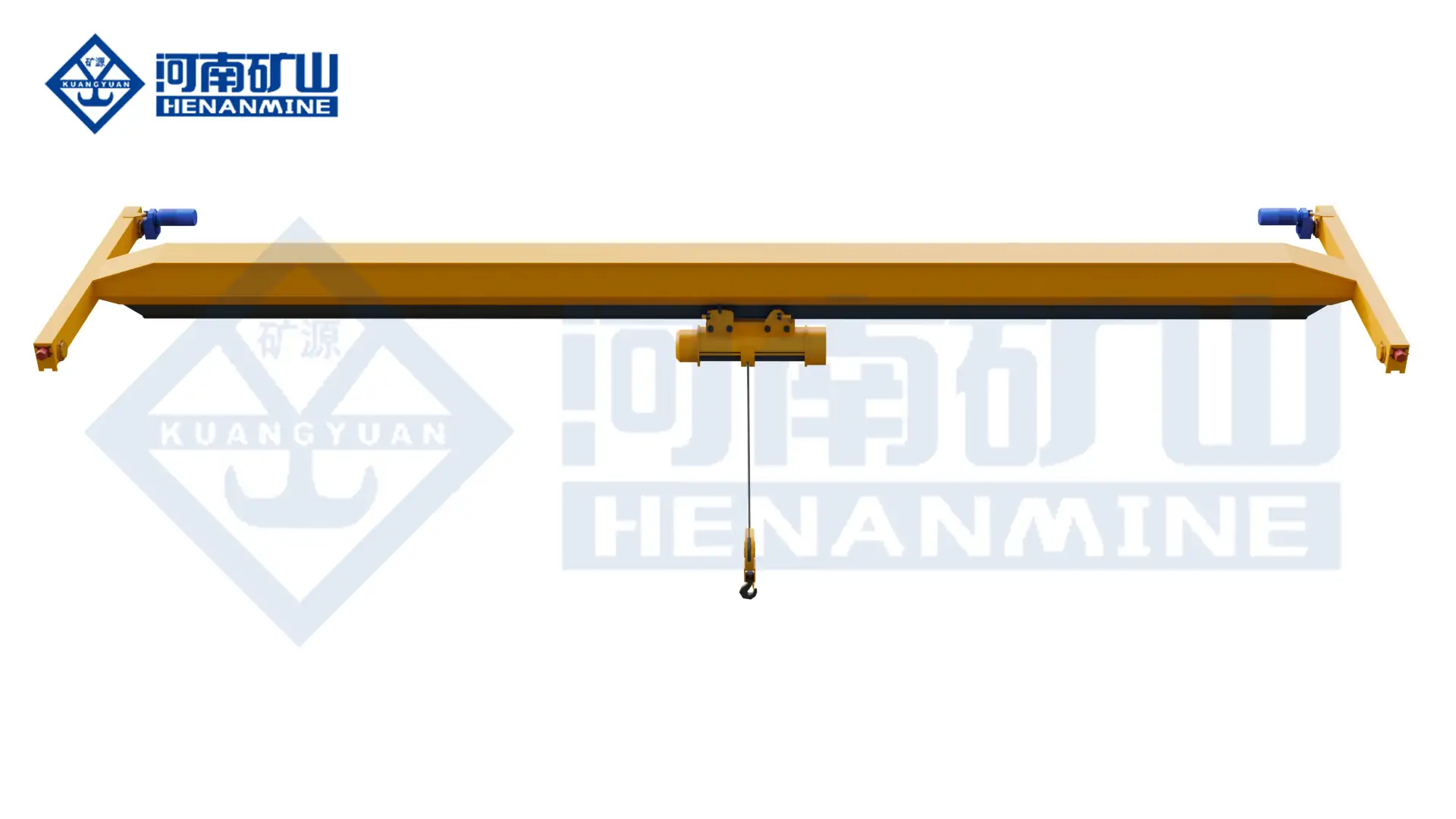
    info@hnksglobal.com
  • 5-Ton Overhead Crane Selection: Bay Dimensions and Working Duty

    5-Ton Overhead Crane Selection: Bay Dimensions and Working Duty

    Selection guide

    5-Ton Overhead Crane Selection: Bay Dimensions and Working Duty

    A five-ton project still needs a defined span, lifting range and operating cycle. Compare the actual hook envelope and support information before selecting a particular crane and hoist configuration.

    Henan Mine CraneSelection guide · Updated 2026Crane selection, project scope and operating requirements
    Henan Mine Crane 5 Ton Overhead Crane
    Henan Mine Crane 5 Ton Overhead Crane
    Project planning notes

    Key points for this crane project.

    1. Start a five-ton selection with the load list
    2. Measure the bay around useful hook coverage
    3. Describe working duty with an operating example
    Read the technical guide

    Start a five-ton selection with the load list

    State that the enquiry uses metric tonnes and identify the maximum load to be handled. List typical loads separately and describe the slings, lifting beam or other attachment. Ask how attachment mass is accounted for in the proposed lifting arrangement.

    Record load dimensions and the intended orientation during transfer. A capacity label does not establish whether a component can pass between machines or be placed at the required station.

    Measure the bay around useful hook coverage

    Provide the runway centreline spacing, travel length and required upper and lower hook positions. Add roof levels, building columns and services to the cross-section.

    Request a drawing showing the proposed hook approaches and crane envelope. Evaluate the pickup and placement points against that drawing. Usable lifting space should be demonstrated at the hook, including the attachment and suspended load.

    Describe working duty with an operating example

    Explain a normal shift: which loads are moved, how often they are moved and the typical travel distances. Identify occasional heavier lifts and periods of intensive production.

    Ask the supplier to state the duty basis for the selected crane and hoist. A five-ton rating does not describe the operating cycle, and a similar crane used elsewhere may have been selected for different service conditions.

    Compare arrangements on the same brief

    Review single-girder, double-girder or suspended alternatives using the same load and building information. Compare the selected hoist position, highest hook level, approaches and support reactions.

    State the operator’s working position and any need for controlled placement. Identify outdoor exposure, dust, heat or other environmental conditions before agreeing the equipment specification.

    Ask for a documented selection response

    Request the proposed configuration, main dimensions, duty basis, support information and electrical requirements. Record assumptions that still depend on a site survey or final attachment selection.

    Henan Mine Crane can use this brief to discuss a five-ton arrangement for the actual bay. Keep the drawing, operating example and scope list together when reviewing the proposal.

    Discuss the crane arrangement for your project.

    A five-ton project still needs a defined span, lifting range and operating cycle. Compare the actual hook envelope and support information before selecting a particular crane and hoist configuration. Share the load, available drawings, working cycle and site conditions with Henan Mine Crane so the required configuration and supply boundary can be discussed.

    Related crane configurations

    5 Ton Overhead Crane

    View product parameters
    Lifting capacity: 5 tSpan: Project-specificLifting height: Project-specific; confirm the required vertical hook travel and available headroom

    Specify a 5 t overhead crane around the load, building and operating cycle. Compare single-girder, double-girder and underhung arrangements for your workshop.

    Single-Girder Bridge Crane

    View product parameters
    Lifting capacity: 1–20 tSpan: 7.5–31.5 mLifting height: 6, 9, 12, 18, 24 or 30 m; capacity-dependent

    Use an LDA single-girder bridge and electric hoist for general workshop material handling. Select the lifting capacity, runway geometry and hoist duty around the building and load.

    Updated 2026 · Henan Mine Crane