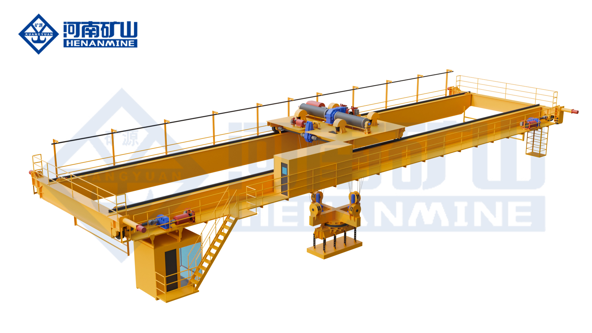
Henan Mine Crane · Engineered Coil Transfer for Pickling Operations
Pickling Line Crane Systems
Process-duty overhead cranes for hot-rolled coil receiving, pickling-line entry feeding, exit-coil removal, buffer storage, inspection, rework and dispatch.
Henan Mine Crane engineers each pickling line crane around the maximum gross suspended load, complete coil envelope, line throughput, pickup and placement interfaces, acid-mist exposure, selected attachment, runway restrictions, control architecture and required operating availability.
PRIMARY SERVICE
Entry, Exit & Buffer Coils
TYPICAL ARCHITECTURE
Top-Running Double Girder
ATTACHMENT OPTIONS
C-Hook, Tong, Mandrel or Magnet
CONTROL LEVELS
Manual, Assisted or Automatic
What Is a Pickling Line Crane?
A pickling line crane is a coil-handling overhead crane serving the receiving, entry, exit and storage areas of a steel strip pickling line. It unloads incoming hot-rolled coils, feeds entry saddles or coil cars, removes pickled coils from the recoiling section, transfers coils through buffers and inspection stations, and loads finished material for the next process or dispatch.
The term does not normally describe a crane carrying steel strip through the acid tanks. During production, strip is continuously transported by the line itself through scale breaking, pickling, rinsing and drying equipment. Crane duties are concentrated around coil logistics and planned maintenance, where controlled handling directly affects line availability and coil condition.
Pickling areas combine high cycle demand with a potentially corrosive atmosphere. Acid chemistry, mist concentration, humidity, condensation, ventilation, washdown practices and distance from the process determine the required protection. A generic outdoor coating or a higher IP rating alone does not establish suitability for acid-mist service.
Henan Mine Crane configures pickling-line systems from double-girder bridge crane and metallurgical bridge crane platforms, combined with a project-specific attachment, corrosion-control package, positioning system and line interface.
Pickling Line Coil-Handling Map
A practical crane specification starts with every pickup, travel and placement point. The following zones commonly require separate operating rules even when one crane spans several functions.
1. Incoming Coil Receiving
Unload hot-rolled coils from trucks, rail wagons or transfer cars and place them on identified saddles. Vehicle envelope, coil eye orientation, lashing removal, edge protection and pedestrian exclusion are included in the lift plan.
2. Entry Section Feeding
Select the scheduled coil and place it on the entry saddle, coil car or pay-off reel interface. Low-speed approach, confirmed centerline, uncoiler availability and attachment-release permissives protect both coil and line equipment.
3. Process-Section Maintenance
Support planned lifting of rolls, pumps, motors, covers and other maintainable assemblies. Maintenance loads, access openings and lifting points are documented separately from routine coil-handling duty.
4. Exit Coil Removal
Remove the completed pickled coil from the exit saddle, recoiler coil car or turnstile only after the line confirms a safe transfer state. Coil bands, tail condition and stable support are verified before travel begins.
5. Buffer, Inspection and Rework
Route coils by grade, order and process status. Storage coordinates, hold areas, inspection stands and rework queues require positive identification and controlled placement on approved supports.
6. Downstream Transfer or Dispatch
Feed a tandem mill, annealing line, coating line or slitter, or load coils into road and rail transport. Order verification and stable final placement close the material-tracking transaction.
One Line Can Require More Than One Crane
Entry and exit bays can have different coil conditions, cycle requirements and environmental exposure. Independent cranes can isolate production logistics, maintenance and dispatch traffic, while overlapping coverage or an emergency transfer plan can support availability.
The handling study records crane-to-crane collision zones, shared runway sections, handover saddles, recovery positions and the production consequence of each single failure.
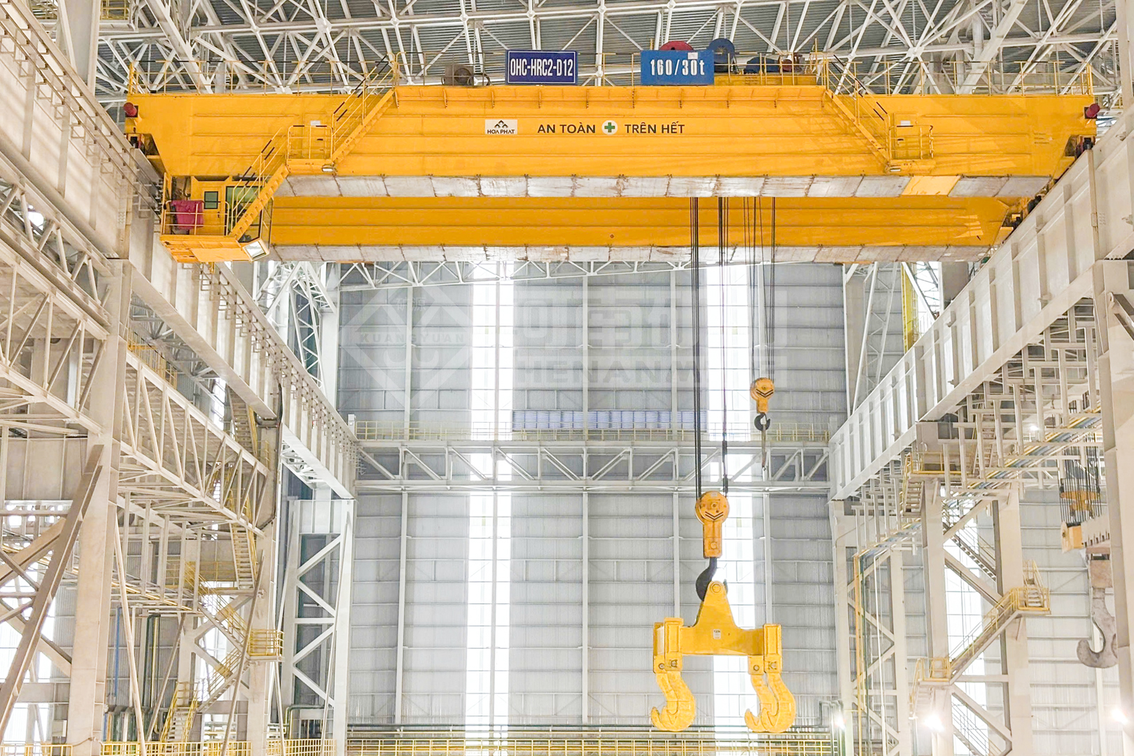
Pickling Line Crane System Architecture
Bridge and End Carriages
Girders, wheels and travel drives are engineered from span, fatigue spectrum, wheel loads, lateral forces, runway stiffness and required approach. Walkways and service platforms support safe inspection.
Process-Duty Hoist
Drum, rope, sheaves, reducer, motor and brakes are sized for the gross suspended load, lift, speed, starts per hour, operating class and required redundancy or emergency lowering philosophy.
Coil Attachment
A C-hook, powered tong, inside-diameter lifter or approved magnet engages the defined coil range. Contact surfaces, engagement confirmation and attachment parking stands form part of the system.
Motion and Positioning
Variable-frequency drives provide controlled acceleration and creep speed. Encoders, laser positioning, anti-sway functions and load-height feedback support repeatable line and saddle approaches.
Electrical and Control System
Panels, PLC, drives, sensors, communications and operator stations are protected for the mapped environment. Diagnostics identify permissive status, faults, maintenance needs and task progress.
Line and Inventory Interface
Handshakes with the line PLC, coil cars, uncoiler, recoiler, turnstile, gates and storage management prevent conflicting movements and preserve coil identity.
Pickling Line Crane Selection Considerations
Nominal coil mass is only one selection input. The crane, attachment and controls are specified from the complete operating envelope and the consequences of delayed or failed transfer.
Coil Envelope
Minimum and maximum coil mass, outside diameter, inside diameter, face width, eye orientation, center-of-gravity range, winding tightness, banding, tail condition and permitted contact areas.
Material Condition
Steel grade, surface scale before pickling, oil or residual moisture after pickling, edge sensitivity, surface-marking limits, temperature and any restrictions on magnetic lifting.
Throughput and Duty
Coils per hour, lifts per shift, loaded travel distance, average and maximum load, production schedule, queuing allowance, annual hours, maintenance windows and outage consequence.
Station Interfaces
Saddle geometry, coil-car stroke, uncoiler and recoiler centerlines, turnstile positions, truck or rail clearances, obstacles, approach distances and attachment release conditions.
Environment Map
Acid chemistry and concentration, mist distribution, chloride or sulfate exposure, temperature, humidity, condensation, washdown, ventilation, dust and the location of cleaner service zones.
Building and Utilities
Span, lift, runway elevation, rail section, wheel-load limits, end approaches, headroom, power supply, cable route, maintenance access, erection opening and future line modifications.
Pickling Line Crane Configurations Compared
The appropriate arrangement follows the duty and process interface. No single configuration is optimal for every pickling line.
| Configuration | Typical Service | Principal Advantages | Engineering Checks |
|---|---|---|---|
| Double-Girder Crane with C-Hook | Receiving, manual entry feeding, exit removal and buffer storage | Mechanically simple attachment, visible engagement and comparatively straightforward maintenance | Accessible coil bore, hook throat and counterweight clearance, lining, rotation, stable orientation and manual engagement time |
| Double-Girder Crane with Powered Coil Tong | High-cycle line feeding, automatic buffers and mixed coil widths | Powered engagement, sensor feedback and stronger automation potential | Jaw range, contact pressure, fail-safe retention, coil width tolerance, mechanism protection and recovery after loss of power |
| Crane with Inside-Diameter Lifter | Defined coil bores and applications requiring limited outer-surface contact | Positive internal engagement and compact outer profile | Bore strength, ID range, insertion depth, tail condition, expansion confirmation and release on a stable support |
| Validated Electromagnetic Crane | Approved ferromagnetic coils or other steel products under a verified lifting plan | No mechanical insertion into the bore and potential remote engagement | Steel grade, curvature, contact area, air gaps, scale or oil, temperature, banding, battery backup, retained-load strategy and proof testing |
| Separate Maintenance Crane or Hoist | Pumps, motors, rolls, covers and service lifts over the process section | Keeps production coil crane duty separate and can target restricted maintenance areas | Actual component weights, certified lifting points, access, acid exposure and interference with line equipment |
Architecture Selection
Top-running double-girder cranes are commonly selected when coil mass, attachment weight, span, duty or positioning equipment requires higher structural capacity and accessible machinery arrangements. Single-girder solutions can suit lighter auxiliary service where duty, headroom and maintenance needs support that choice.
A rotating hook block or powered attachment rotation may be required when coil eye orientation changes between transport, storage and line stations. The rotating envelope is verified against saddles, guards, columns and adjacent crane structures.
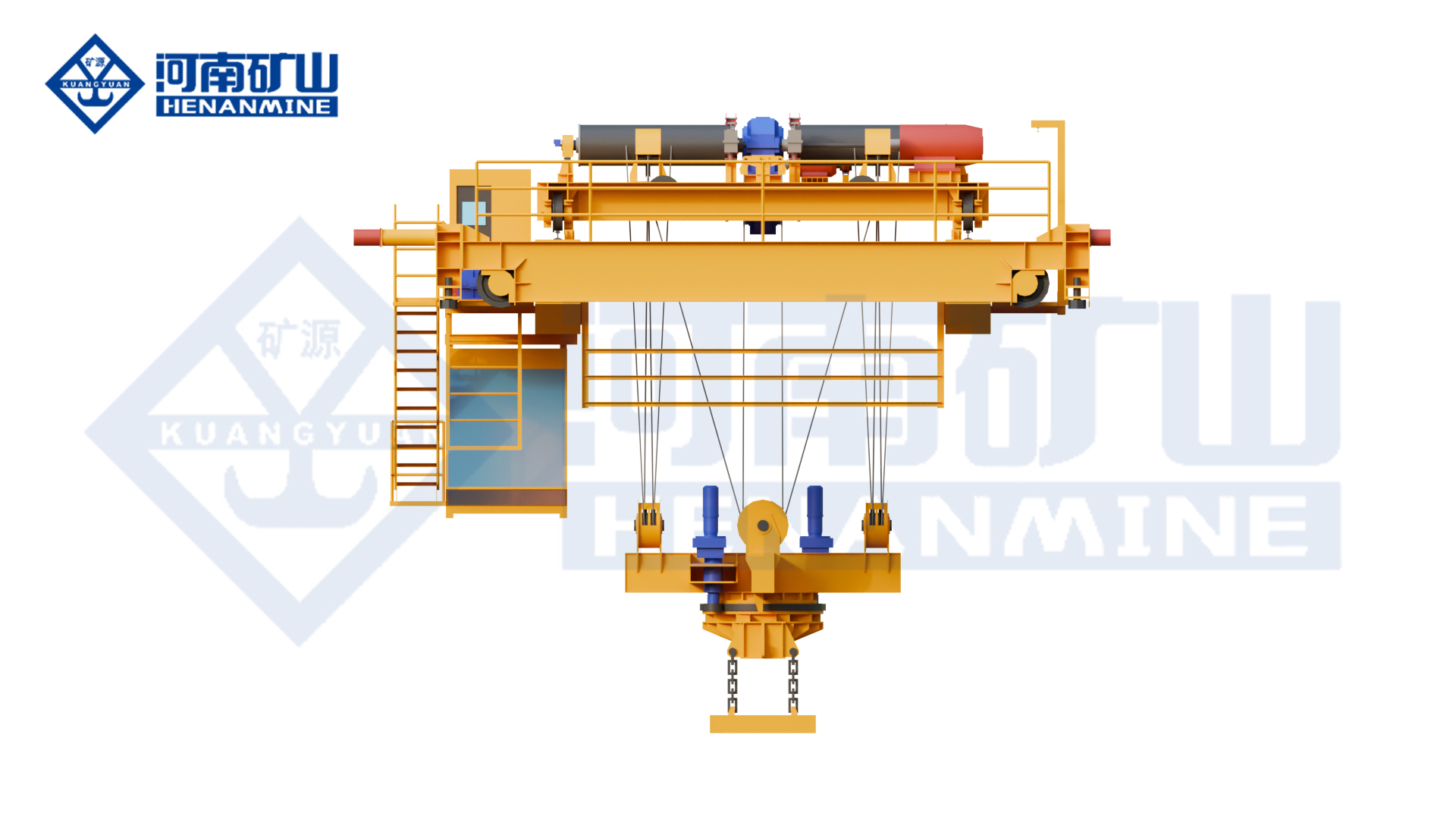
Capacity, Duty and Performance Definition
Gross Suspended Load
The load calculation includes maximum coil mass plus the complete attachment, hook block, rotation mechanism, cables and any permanent equipment below the hoist. Capacity margin is not a substitute for a defined coil range or controlled attachment geometry.
Operating Class and Load Spectrum
Crane classification is selected from total working cycles, distribution of light and heavy loads, motion running time, starts per hour and expected service life. A crane that feeds every production coil normally requires a different fatigue evaluation from an occasional maintenance crane of the same rated capacity.
Speeds and Cycle Time
Main speeds are balanced against travel distance, line takt time, suspended-load stability and available deceleration zones. High top speed does not guarantee a shorter safe cycle. Controlled acceleration, anti-sway and accurate final approach often produce more repeatable throughput.
Performance Data for the Specification
- Maximum gross suspended load and complete coil range
- Required hook or attachment travel and end approaches
- Hoist, trolley and bridge main and creep speeds
- Coils per hour and defined reference handling cycle
- Placement tolerance at each automatic station
- Availability target and planned maintenance allowance
- Noise, power, braking and emergency operating criteria
Coil Attachments for Pickling Lines
The attachment controls engagement, load stability and coil contact. Its mass and center of gravity also affect crane capacity, headroom and wheel loads.
C-Hook
Suitable where the coil bore is accessible and the hook can enter without striking the saddle or line equipment. Throat depth, lower-arm section, counterweight, tip shape, lining and permissible coil range are engineered together.
Powered Coil Tong
Powered arms or jaws engage a defined coil range. Position feedback, load confirmation and fail-safe retention support assisted or automatic cycles, while moving parts require accessible inspection and corrosion protection.
Inside-Diameter Lifter
An expanding or positive-locking device engages the bore. ID tolerance, insertion depth, bore integrity, activation state and a mechanically secure lifting condition require verification for every coil family.
Electromagnetic System
Magnetic lifting is considered only after material, curvature, contact condition, air gap, surface oil or scale, temperature and retained-load behavior are validated. Ferromagnetic material alone does not establish a safe lifting capacity.
Hook and Spreader Package
A conventional hook, beam or maintenance attachment can support non-coil lifts. Changeover controls, dedicated stands, identification and proof-test records prevent an unapproved attachment from entering a production task.
Surface Protection
Replaceable pads, rounded contact edges and controlled contact pressure can reduce marking. Material compatibility, trapped contamination, inspection frequency and pad wear limits are specified.
Acid-Mist and Corrosion-Control Design
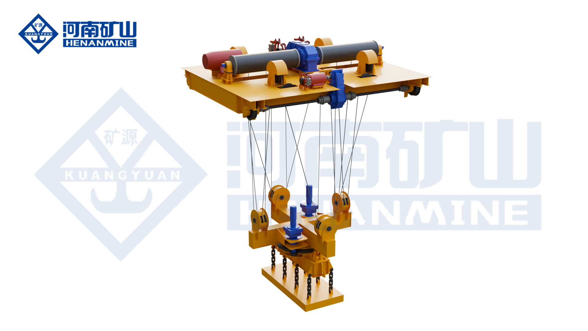
Corrosion protection is selected from the actual exposure map rather than a generic “acid-proof crane” label. Carbon-steel strip lines often use hydrochloric or sulfuric acid systems, while stainless and specialty lines can use different chemistries. Concentration, temperature and ventilation materially change the exposure.
| Design Area | Required Input | Possible Engineering Response |
|---|---|---|
| Steel Structure | Corrosivity, acid species, condensation, washdown and expected service life | Prepared substrate, compatible coating system, sealed details where appropriate, drainage and defined inspection or repair intervals |
| Electrical Equipment | Mist, humidity, temperature, conductive deposits and cooling demand | Selected enclosure and sealing, protected cable entries, conditioned or pressurized cabinets where justified, anti-condensation heating and corrosion-resistant terminals |
| Mechanical Components | Direct exposure, lubricant compatibility, service interval and cleaning method | Protected brakes and bearings, compatible seals and lubricants, guarded rope path, replaceable wear parts and remote lubrication points |
| Fasteners and Small Parts | Galvanic compatibility, crevice exposure and maintenance practice | Compatible materials and coatings, isolated dissimilar metals, accessible replacement and controlled tightening procedures |
| Layout and Ventilation | Mist plume, exhaust arrangement, prevailing air movement and cleaner zones | Locate panels and service points away from concentrated mist, avoid liquid traps and coordinate crane route with fume capture equipment |
Line Integration, Positioning and Automation
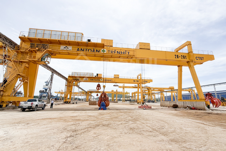
Control scope can range from cabin or radio operation to assisted positioning and fully automatic coil transfer. Automation is defined by the process states, field interfaces and recovery strategy, not only by coordinate control.
Station Handshakes
The line PLC confirms station identity, coil availability, coil-car position, uncoiler or recoiler state, guards, gates and permission to enter. The crane returns approach, placement and task-complete states.
Coil Identification
Barcode, RFID, operator confirmation or production data links the physical coil with grade, order, dimensions, process status and destination. Exception rules prevent an unidentified coil from entering an automatic task.
Position and Anti-Sway
Absolute or referenced position data, controlled acceleration, sway reduction, load-height feedback and final approach logic support repeatable placement without using line equipment as a mechanical stop.
Traffic and Protected Zones
Crane-to-crane separation, vehicle lanes, restricted process areas, temporary maintenance zones and personnel access states are enforced through the agreed safety architecture.
MES or WMS Interface
Task messages define source, destination, coil identity and priority. Interface design also covers acknowledgements, duplicate commands, time synchronization, audit history, cybersecurity and network loss.
Manual Recovery
Every automatic sequence requires a controlled safe state and a documented recovery path for sensor failure, lost communications, incomplete engagement, blocked destination or interrupted power.
Safety Functions and Operating Boundaries
Overload and Motion Limits
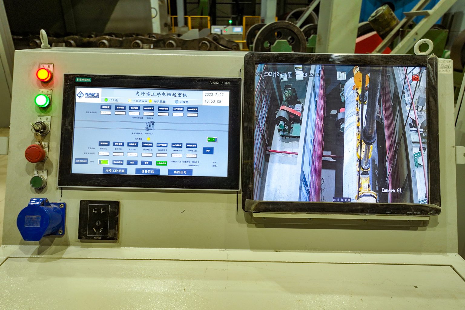
Rated-capacity protection, normal and final motion limits, brakes, buffers, travel warnings and monitored speed zones are selected under the governing code and risk assessment.
Attachment Permissive
Hoisting begins only after the approved engagement state is confirmed. Release is inhibited until the coil is supported, the destination is correct and the release sequence is authorized.
Restricted-Area Control
Barriers, gates, scanners, warning devices and administrative controls are coordinated around line entrances, vehicles, storage aisles and automatic crane operating zones.
Collision Avoidance
Adjacent cranes, building columns, line structures, high coils and temporary maintenance equipment are included in the collision model and stopping-distance calculation.
Energy Isolation
Lockout points, stored-energy release, access platforms and local isolation are coordinated for crane maintenance and work on interfacing line equipment.
Abnormal Events
The operating concept covers power loss, retained suspended load, failed attachment sensor, displaced coil, unavailable destination, fire alarm, ventilation loss and evacuation.
Runway, Building and Maintainability Interfaces
Existing Runway Verification
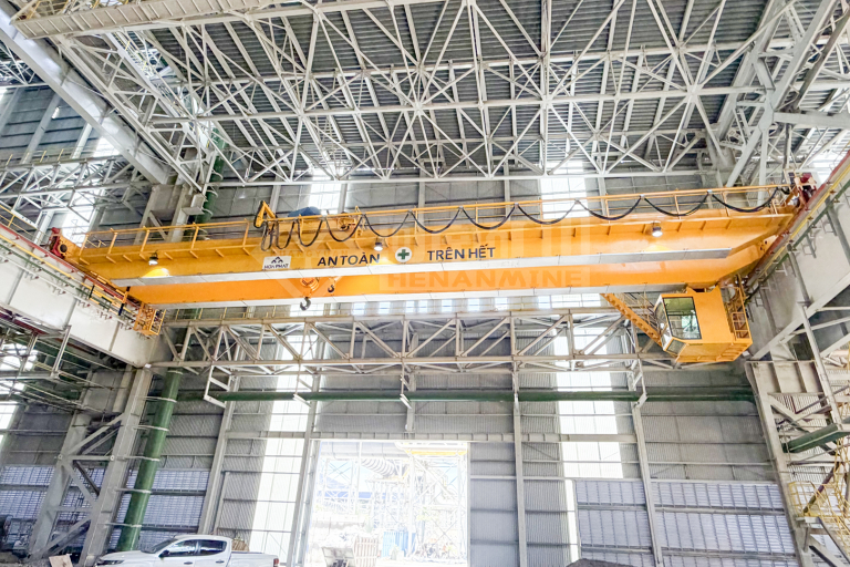
Reuse requires verification of rail section and alignment, beams, brackets, columns, connections, foundations, fatigue history and measured condition. Maximum and minimum wheel reactions, lateral forces, buffer loads and electrification loads are issued for structural review.
Clearance and Approach Study
Hook approach, C-hook counterweight, tong arms, rotating envelope, cabin, walkways and festoon or conductor systems are checked in three dimensions against roof steel, ducts, exhaust equipment, lighting and the pickling line.
Maintenance Access
Inspection platforms, guarded access, safe parking position, component removal paths, lifting points, rope replacement space and isolation stations are defined before fabrication. Critical sensors and corrosion-prone parts remain visible and replaceable.
Site Data Required
- Building and runway drawings with verified dimensions
- Rail elevation, span, length, end stops and expansion joints
- Existing allowable vertical and horizontal reactions
- Roof, duct, tank, line and vehicle clearances
- Erection opening, laydown area and shutdown window
- Electrical supply, grounding and communication network
- Environmental survey and hazardous-area documentation
Applicable Standards and Acceptance Testing
The contract identifies the governing jurisdiction, crane design code, electrical standard and below-the-hook lifting-device rules. Common reference frameworks include ISO 4301, ISO 9927 and ISO 12480-1; EN 13001 and EN 15011; CMAA 70 and ASME B30.2; ASME BTH-1 and ASME B30.20 for applicable lifting devices; IEC 60204-32 for hoisting-machine electrical equipment; and ISO 13849-1 or IEC 62061 for safety-related control functions.
ISO 12944 can inform protective-paint-system selection, while IEC 60529 addresses enclosure ingress ratings. IEC 60079, ATEX or IECEx requirements apply only where the project hazardous-area assessment establishes that scope. Local law and the approved contract remain controlling.
Design Review
Confirm load cases, classification, general arrangement, wheel loads, attachment envelope, corrosion schedule, electrical architecture, safety functions, interfaces and inspection access.
Factory Acceptance Test
Verify assemblies, controls, drives, braking, limits, sensors, attachment logic, alarms, interface simulation, documentation and agreed inspection records before shipment.
Site Acceptance Test
Test crane motions, load protection, representative coils, all transfer stations, placement tolerance, collision zones, line handshakes, abnormal states, manual recovery and operator procedures.
Published Adjacent Steel Mill References
Published references demonstrate relevant steel-production crane and automation capabilities. They do not replace a project-specific pickling-line design review.

More Than 100 Lifting Units for a Southeast Asian Steel Mill
Henan Mine Crane reports commissioning more than 100 lifting units for a large steel mill, including a 160 t double-girder overhead crane, slab clamping cranes, lower-rotating electromagnetic hanging-girder cranes and double-girder double-trolley gantry cranes.
Evidence boundary: the published reference demonstrates multi-crane steel-mill delivery capability; it does not identify the units as pickling line cranes.
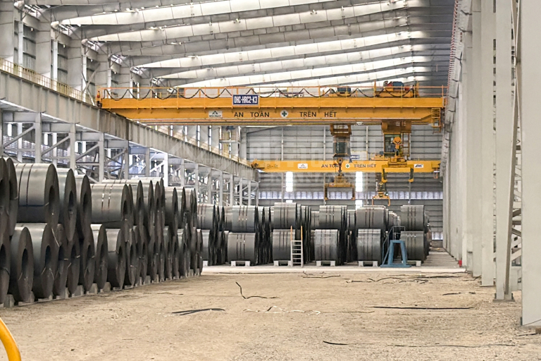
Automatic Electromagnetic Handling Platform
Henan Mine Crane publishes an automatic electromagnetic hanging-girder solution with automatic operation, rigid-guide anti-sway, MES integration and multiple operating modes. These functions are relevant to automatic material-transfer architecture.
Evidence boundary: the published solution is not presented as a pickling-line delivery, and magnetic suitability for a specific coil remains subject to load testing and risk assessment.
Pickling Line Crane Price and Budget Scope
A complete pickling line crane has no reliable catalog price because capacity, duty, attachment, corrosion protection, automation, runway interfaces and installation scope change the engineered package. Public prices reviewed on 21 September 2026 provide market context only and are not technically equivalent offers.
| Public Market Reference | Published Price | What the Figure Represents | Major Exclusions or Limits |
|---|---|---|---|
| 10 t or 25 t C-Type Coil Lifting Hook Listing | US$2,500–2,600 per set | Marketplace attachment listing | Not a crane; load range, material, lining, proof test, documentation, freight and project compliance require confirmation |
| 10 t Top-Running Double-Girder Crane Kit Listing | US$33,020 | Advertised crane kit with hoists | Listing states “crane kit only”; excludes a pickling-line attachment, project corrosion package, runway, building work, installation and line automation |
| Generic 60 t Double-Beam Bridge Crane Listing | US$55,000–115,000 per set | Marketplace complete-crane price signal | No normalized pickling-line duty, coil attachment, acid-mist protection, automatic interfaces, civil works, erection or acceptance scope |
| Complete Engineered Pickling Line Crane Project | Project-specific RFQ | Crane, attachment, controls and contracted project services | A valid total requires an approved technical specification, site data, commercial boundary and destination |
Primary Price Drivers
Capacity and span; operating class and speeds; C-hook, tong, mandrel or magnet; rotation; corrosion-control system; cabin and HVAC; positioning and anti-sway; automatic controls; safety zoning; line PLC and MES/WMS interfaces; runway electrification; documentation and local certification.
Commercial Scope to Reconcile
Runway rails and beams; structural strengthening; freight and insurance; taxes and duties; site supervision; mechanical and electrical installation; lifting equipment for erection; commissioning; load-test weights; training; spares; warranty support and production acceptance testing.
Engineering and Procurement Deliverables
A procurement-ready proposal defines performance, interfaces, evidence and commercial boundaries in measurable terms.
Technical Proposal
Design basis, general arrangement, main mechanisms, duty classification, speeds, attachment concept, protection package, control level and stated deviations.
Interface Schedule
Runway reactions, power and communications, line I/O, station coordinates, civil boundaries, erection needs, environmental inputs and third-party responsibilities.
Safety Documentation
Risk-assessment inputs, safety-function list, restricted zones, attachment logic, isolation concept, emergency states and required local conformity documents.
Quality Records
Material and welding records as specified, inspection and test plans, coating records, component certificates, attachment proof testing and factory test reports.
Operation and Maintenance
Manuals, lubrication plan, corrosion inspection, adjustment limits, fault recovery, spare-parts list, training scope and recommended preventive-maintenance intervals.
Commercial Schedule
Price, Incoterm, delivery milestones, packing, installation boundary, commissioning, training, acceptance, warranty, exclusions, validity and optional services.
Pickling Line Crane RFQ Information
The following data allows the crane, attachment, environmental protection, interfaces and project scope to be priced on a consistent basis.
Coil and Attachment Data
Material and grade; minimum and maximum mass, OD, ID and width; eye orientation; temperature; surface and oil condition; banding; center of gravity; contact restrictions; proposed C-hook, tong, ID lifter or magnet.
Process and Duty Data
Entry, exit, storage and dispatch sequence; station coordinates; lifts per hour; shifts; annual hours; load spectrum; travel distances; target cycle; availability target and required contingency.
Environment and Site Data
Acid chemistry, concentration and temperature; mist or corrosivity survey; humidity, condensation and washdown; ventilation; span, runway and clearances; power supply; building drawings and destination.
Controls and Commercial Data
Manual, assisted or automatic operation; placement tolerance; line PLC and MES/WMS protocols; safety zones; required code; Incoterm; freight, installation, commissioning, test and documentation boundaries.
Frequently Asked Questions
Where does a pickling line crane operate?
Its principal production duties are usually in the incoming-coil, line-entry, line-exit, buffer, inspection and dispatch zones. It may also support planned maintenance, but the steel strip travels through the pickling tanks on the line equipment.
Does every pickling line crane need acid-resistant construction?
Protection depends on measured or specified exposure. Acid chemistry, mist, ventilation, humidity, condensation and washdown are mapped by zone. Coatings, enclosures, seals, materials and maintenance intervals are then selected for each zone.
Is a C-hook or powered coil tong more suitable?
A C-hook offers mechanical simplicity where the bore is accessible. A powered tong offers automated engagement and feedback for high-cycle service but adds mechanisms and maintenance. Coil geometry, cycle rate, access and control level determine the choice.
Can an electromagnetic crane handle pickled coils?
Only after the material grade, curved contact, air gaps, oil or moisture, banding, temperature, required holding force and power-loss behavior are validated. A mechanical attachment may be preferable where magnetic performance is uncertain.
How is rated capacity determined?
The starting value is the maximum gross suspended load: coil plus attachment, hook block and all equipment carried below the hoist. Operating class, dynamic effects, load distribution and governing code are then applied.
How much does a pickling line crane cost?
Public figures range from low-cost attachment or generic crane listings to substantially broader engineered projects. A defensible price requires coil data, span, duty, attachment, corrosion protection, automation, runway scope, destination and installation boundary.
Can the crane connect to the line PLC and MES?
Yes. The interface specification defines station states, task messages, coil identity, coordinates, acknowledgements, safety ownership, network protocol, cybersecurity, diagnostics and recovery after interrupted communications.
Can an existing runway be reused?
Only after its geometry, condition, fatigue history, rail alignment, beams, columns, connections and foundations are verified against the proposed vertical, lateral, longitudinal and buffer reactions.
Related Pickling Line Crane Products and Solutions
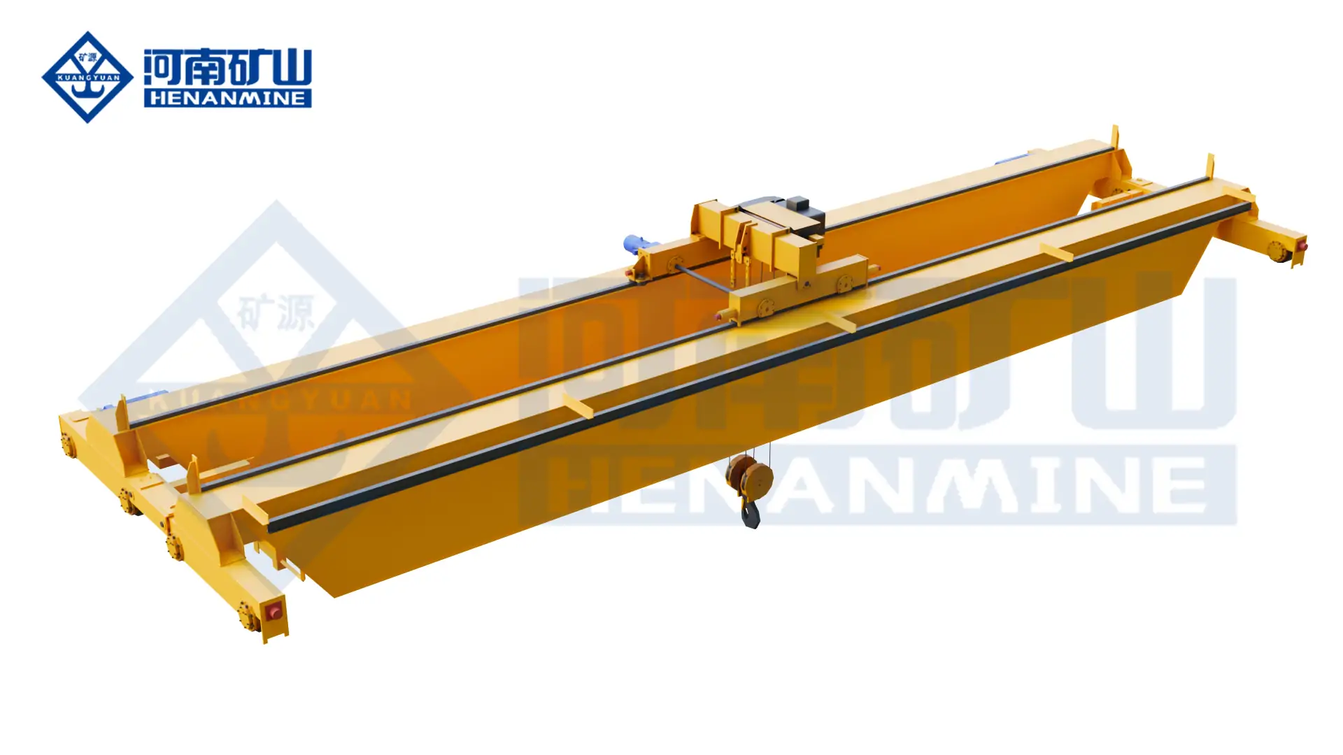
Double-Girder Bridge Crane
Configurable top-running platform for a C-hook, powered tong, mandrel or other project-specific attachment.
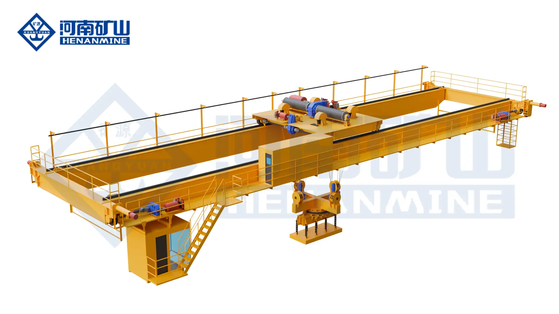
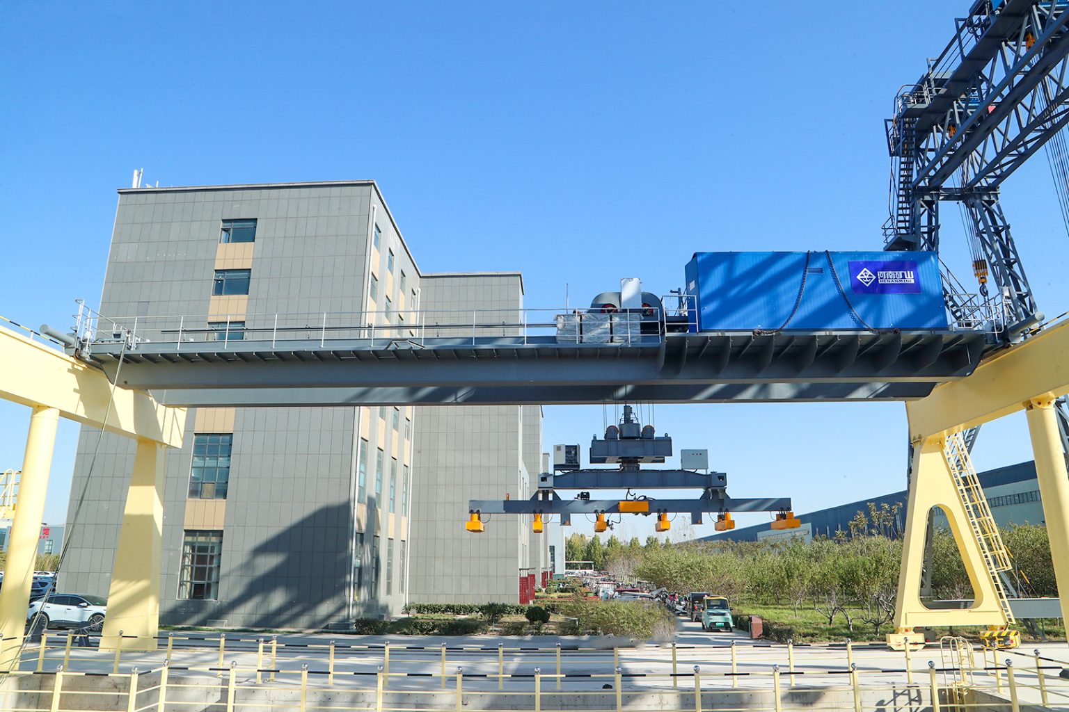
Electromagnetic Hanging Crane
Published 5–50 t magnetic handling platform for approved ferromagnetic loads and operating conditions.
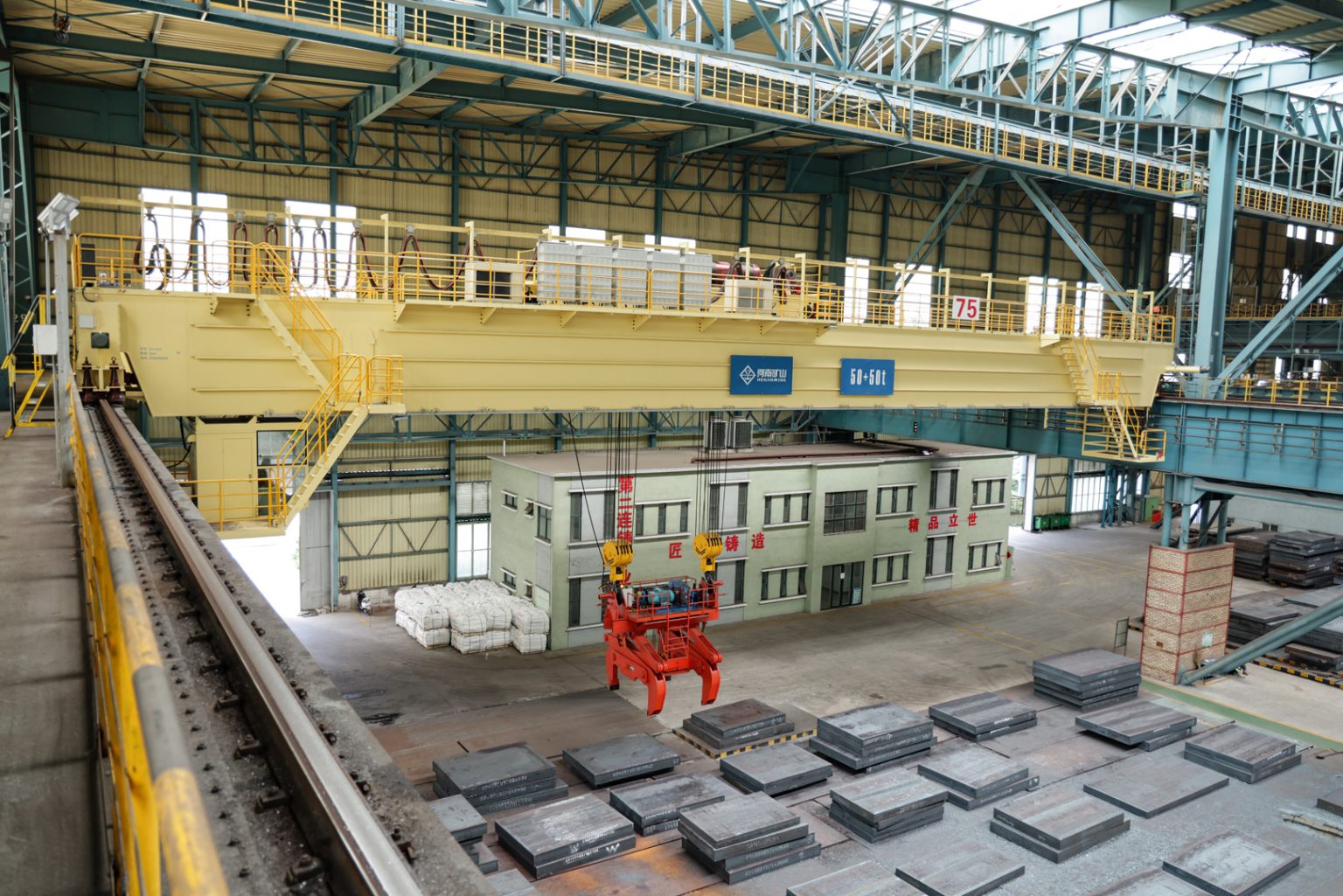
Metallurgical Bridge Crane
Process-duty crane category for specified steel-production loads, duties and operating environments.
Steel Mill Crane Systems
Plant-wide planning for raw material, process-line, warehouse, dispatch and maintenance handling.
Request a Pickling Line Crane Quote
Submit the coil range, handling sequence, line throughput, attachment preference, acid chemistry and exposure data, span, lift, runway information, control level, line-interface requirements, power supply, project destination and supply boundary. Henan Mine Crane will prepare a configuration-based technical and commercial proposal.